Article
Microfluidic long-term gradient generator with axon
separation prototyped by 185 nm diffused light
photolithography of SU-8 photoresist
Nobuyuki Futai1, *, Makoto Tamura1, Tomohisa Ogawa2, Masato Tanaka3
1 Shibaura Institute of Technology, 3-7-5 Toyosu, Koto-ku, Tokyo 135-8548 Japan 2 Tokyo Medical and Dental University, Bunkyo-ku, Tokyo 113-8510 Japan 3 Tokyo Denki University, Hiki-gun, Saitama 350-0394 Japan
* Correspondence: [email protected]; Tel.: +81-3-5859-8008
Abstract: We have developed a cast microfluidic chip for concentration gradient generation that contains a thin (~5 μm2 crosssectional area) microchannel. Durable 2 μm-high microchannel mold features with smooth bell-shaped sidewalls were fabricated by exposing SU-8 photoresist to diffused 185 nm UV light emitted from a low-cost ozone lamp from the backside of the substrate to ensure sufficient crosslinking of small regions of the SU-8 photoresist. An H-shaped microfluidic configuration was used, in which the thin channel was able to maintain constant diffusion fronts beyond purely static diffusion confirmed with experiment. We also demonstrated the long-term effects of a gradient of nerve growth factor on axon elongation by primary neuronal cells cultured in the microfluidic channel.
Keywords: SU-8, microchannel, prototyping, microfluidic gradient generator, axon elongation
1. Introduction
Cells naturally respond to soluble factor gradients through processes such as chemotaxis, gradient-dependent differentiation, and axon guidance. The generation of concentration gradients in media covering cells seeded in microfluidic devices is a useful tool for investigating such processes [1]. In addition, the microfluidic approach to gradient generation is applicable to other microorganisms, such as bacteria [2] and roundworms [3], and has higher throughput and is more efficient than generating gradients in traditional culture systems[4].
Challenges remain, however, in designing microfluidic gradient generators simple to fabricate and convenient to use. Such devices are still underused because microfluidic, or lab-on-a-chip, technologies lack technical simplicity[5]. They often require systems for complex microfabrication and/or microfluidic control techniques that many end users find difficult to adopt. Another scientific difficulty arises in calibrating the gradient, i.e. in estimating or predicting the spatiotemporal concentration profile in a chip that has a complex microfluidic configuration both in terms of channel layout and external equipment.
We have developed a cast microfluidic chip that contains a thin (~2 µm in the top height) but high-aspect-ratio (0.5 ~ 1.0) microchannel connected to thicker microfluidics. The thin channel has high flow resistance and supports diffusion-based gradient generation and easy handling, including priming. The end of the thin channel can be considered as a point source that facilitates the prediction and analysis of the spatiotemporal concentration gradient generated. The design of the chip is also comparable to traditional chemotaxis chambers, such as the Zigmond Chamber [6] or Dunn Chamber [7], allowing for a straightforward understanding of its usage. In addition, we note that the fabrication method of molds for casting should also be simple enough for end users to prepare.
To fabricate the casting mold with small microchannel features, we also have developed a simple fabrication method for durable SU-8 microchannel mold with ~ 5 μm2 crosssectional area that only requires a low pressure mercury lamp (“ozone lamp”) to expose SU-8. The simplicity of this method
was comparable to a well-known soft lithographic rapid prototyping of SU-8 features at 8 µm resolution using photoplotted (emulsion) masks[8]. However, the limitation in resolution of this simple rapid prototyping method comes from the resolution/transparency of the photoplotted masks [9] and insufficient crosslinking of SU-8 photoresist by UV light through an aperture smaller than 8 µm. Soft lithography-friendly prototyping of features smaller than 1 µm has been achieved by using several non-UV patterning methods, such as e-beam direct writing of SU-8 photoresist [10], nanocracking [11] and roof collapse [12]. These non-UV methods are simple, but can be either costly or have limitations in how the channel layout can be defined. We successfully fabricated SU-8 thin line features from an emulsion photomask by exposing SU-8 photoresist to diffused short-wavelength (185 nm) UV light emitted from an ozone lamp from the backside of the substrate to ensure sufficient crosslinking of small regions of the SU-8 photoresist.
2. Materials and Methods
2.1. Design of the Microfluidic Chip
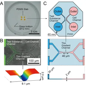
The microfluidic gradient generator chip we developed and its fluidic configuration are shown in Figure 1. As shown in Figure 1A, the chip consists of a glass-bottom dish and a slab made of poly(dimethylsiloxane) (PDMS) with microfluidic channel features and two inlet/outlet pairs. Figure 1B shows the microchannels including one thin channel with “bell-shaped” sidewalls (2 µm high × 40 µm long) and with bifurcate ends. Thick channels (200 µm wide × 30 µm high) that were extended from each bifurcated end of the thin channel so that the fluidic configuration is H-shaped, as shown in Figure 1C. The H-shaped configuration with mixed-height microchannels facilitates the introduction and replacement of liquids in and near the thin channel.
The left-hand side of the H-shape is used for introducing test substances, and the channel height decreases at the branch point to ensure complete liquid exchange and to prevent sudden changes in pressure that could push or pull liquids into the thin channel. The end of the thin channel that connected to a widening channel can be considered as a point source of a test substance. The right-hand side of the H-shape is used for introducing cells and is connected to two 30 µm-high channels that allow for easy cell loading under low shear stress and allow cell culture within the channels for several days.
Applying Laplace pressures at the inlet/outlets by placing droplets on them can easily generate flow through the chip. Since the microfluidic route, including the thin segment, has high fluidic resistance, only macroscopic differences between the size of droplets on the inlet and outlet generate flow. This “insensitivity” makes it easy to start/stop the flow in the thin channel and to generate gradients using a commercially available single channel pipette.
The Laplace pressure 𝑃 for the droplet height ℎ𝑑 is given below:
𝑃 =
4ℎ𝜎
ℎ
𝑑2+ 𝑅
2 (1)where 𝜎 is the surface tension (72.8×10⁻³ N/m for water at 20 °C) and 𝑅 the radius of inlets/outlets. Since the depth and the diameter of the inlets/outlets are 1 mm and 2 mm, respectively, we can easily generate Laplace pressures ranging from approximately −60 to +60 Pa by adding or subtracting ℎ𝑑
2.2. Fabrication of Microfluidic Chip
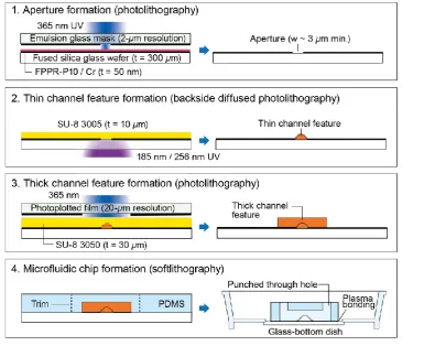
The fabrication processes are illustrated in Figure 2. The photopatterning of SU-8 photoresist was performed twice to successfully define both thin and thick microchannel features. The first patterning of SU-8 photoresist into thin channel features required a high exposure energy dose only into the small regions of the unexposed SU-8 layer. Thus, the combination of backside exposure of SU-8 photoresist[13] and exposure to 185 nm UV was used for the first SU-8 patterning. The “photomask” for the first exposure must be in contact with the SU-8 layer to minimize blurring and detachment of SU-8 features from the substrate. Therefore, the SU-8 layer was coated on the patterned Cr film on the glass substrate. The second patterning of SU-8 photoresist consisted of conventional processes using standard 365 nm UV with a glass emulsion photomask.
First, the layout of thin channels defined by apertures on a low-cost emulsion photomask was transferred to a Cr film on a glass wafer. A 50 nm Cr film was deposited on a synthetic fused silica glass wafer (50mm ×50mm × t0.3 mm, Seiken Glass, Tokyo, Japan) using a sputter coater (SVC-700RFII, Sanyu Electron, Tokyo, Japan). The wafer was then coated with a 1 µm thick layer of positive photoresist (FPPR-P10, Fuji Chemicals Industrial, Tokyo, Japan) by spin-coating at 5,000 rpm for 30 s and then baking at 95 °C for 2 min. The photoresist layer was exposed to collimated 365nm UV
from a spot UV source (L7212-02, Hamamatsu, Shizuoka, Japan) with a dose of 125 mJ/cm2 through an emulsion glass photomask (2 µm resolution, Shin-eisha, Tokyo, Japan), was then developed with 2.38% TMAH (Tama Chemicals, Kanagawa, Japan) and hard baked at 95 °C for 10 min. The exposed Cr film was wet etched in a solution containing 17 wt% (NH4)2Ce(NO3)6 and 7 wt% NH4NO3 (Wako Chemical, Osaka, Japan) in water. The photoresist was removed with dimethyl sulfoxide followed by immersion in 1 vol% alkaline cleaning solution (TMSC, Tama Chemicals) at 65 °C for 10 min.
Next, the SU-8 photoresist layer on the patterned Cr film was exposed to UV from the backside to form thin channel features. A negative photoresist (SU-8 3005, Nippon Kayaku, Tokyo, Japan) was spun at 4,500 rpm for 30 s to form a layer with a thickness range of 8–10 µm and was dried at 95 °C for 10 min. The SU-8 layer was then exposed to 185 nm and 254 nm UV from a low-pressure mercury vapor lamp (GL-4Z, Kyokko Denki, Tokyo, Japan). The UV power was measured as 0.2 mW/cm2 @ 185 nm with an UV power meter (C9536/H9535, Hamamatsu). The exposure time was controlled by an electronic shutter (DSS10, Uniblitz, Rochester, NY, USA) so that the exposure dose was 0.1 mJ/cm2. Following the backside exposure, a thick SU-8 layer was patterned using conventional methods. A 30 µm thick negative photoresist layer (SU-8 3050, Nippon Kayaku) was coated by spinning at 5,000 rpm for 30 s, dried, and exposed to the collimated 365 nm UV with a dose of 300 mJ/cm2 through an emulsion glass photomask (20 µm resolution, Topic-dic, Tokyo, Japan) aligned to the first SU-8 layer
using a 3-axis mechanical stage. Both exposed SU-8 layers were post-exposure baked at 95 °C for 10 min and were developed with 1-methoxy-2-propyl acetate.
Finally, the SU-8 features were transferred to a PDMS slab, which was then bonded to the bottom of a glass bottom dish for cell culture. A PDMS prepolymer (KE106, Shin-etsu, Tokyo, Japan) was poured onto the SU-8-pattened surface to make a 1 mm thick layer, cured at 65 °C for 90 min, and demolded by peeling. A slab containing one H-shaped channel upper was cut from the peeled PDMS, and four 2 mm diameter holes were punched in the circular slab. The punched PDMS slab was bonded to a 35 mm diameter glass-bottom dish (3971-035, Iwaki, Tokyo, Japan) after air plasma treatment at 20 mA and 40 Pa for 30 s in a plasma chamber (SC-708, Sanyu Electron).
2.3. Measurement of Aperture and Channel Dimensions
Cr aperture patterns on the glass wafers were photographed with a laser confocal microscope (OLS4000, Olympus, Tokyo, Japan). The texture and height images of the surface of PDMS slabs with thin channel upper features were acquired by an atomic force microscope (AFM5000II, Hitachi, Tokyo, Japan). Data from both microscopes were analyzed using Gwyddion v2.51 height field and image analysis software (http://gwyddion.net/).
2.4. Evaluation of Diffusion on Chip
An assembled chip was primed by introducing 1 µl of phosphate buffered saline (PBS; 10010, Invitrogen, Grand Island, NY, USA) to the inlets/outlets. To avoid bubbles, the water was first poured into one of the inlets, then into its outlet, followed by pouring into the other inlet, and finally into its outlet in series at 15 ~ 20 s intervals. To load the thin channel with fluorescence, PBS at the outlet and the inlet of the Test Substance Channel (the left ports shown in Figure 1C) was replaced with 1 µl of 10 µM solution of Alexa Fluor 488 (A33077, Invitrogen). Next, 1µl of PBS was added to two ends of Cell Channel, 0.5 µl of PBS and the same Alexa Fluor solution were added to the outlet/inlet of Test Substance Channel. The device was then incubated at 37 °C, 95%RH and 5% CO2. A fluorescence laser confocal microscope (FV10i, Olympus) was used for obtaining fluorescence images of microfluidic channels.
Fluorescence profiles inside the thin channel were fit to the model of one-dimensional static advection-diffusion from a continuous point source:
𝐶(𝑥) =
𝐶
max− 𝐶
minexp Pe − 1
{exp (
Pe ⋅ 𝑥
𝐿
) − 1} + 𝐶
min (2)where 𝐶(𝑥) is the measured concentration as a function of the position 𝑥 along the thin channel length 𝐿 (0 ≤ 𝑥 ≤ 𝐿), 𝐶max and 𝐶min the maximum and minimum concentration values within the
channel region, and Pe Peclet number defined using 𝐿 as relevant length scale. 𝐶(𝑥), 𝐶max and
𝐶min can be replaced to corresponding fluorescence intensity according to Lambert-Beer Law when
the fluorescent dye concentration is low enough. We calculated Pe by fitting of each fluorescence intensity profile to Equation (2) using Igor Pro 7.0 data analysis software (Wavemetrics, Portland, OR, USA).
2.5. Primary neural cell culture on-chip
For the axon elongation experiment, primary dorsal root ganglion (DRG) cells were introduced to the chip. The DRG cells were freshly isolated from E7 chick embryos by dissection, and were dissociated into DRG cells using 0.25% trypsin (15090, Invitrogen). The channels were coated with a solution of 1 wt% poly-D-lysine (P7886, Sigma, St Louis, MO, USA) and filled with DMEM/F12 medium (11320, Invitrogen) supplemented with ITS solution (#1074547, Roche, Basel, Switzerland).
After the confirmation of cell attachment and starting neurite growth, the inlet/outlet of the Cell Channel were replaced to 5 µl of fresh medium. The outlet and the inlet of the Test Substance Channel were then replaced to 4.5 µl of medium, and 4.5 µl of medium with 50 ng/ml NGF, respectively, to generate a gradient of NGF.
3. Results and Discussion
3.1. Size of the microfluidic channels
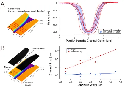
We evaluated the shape, the stability and controllability of the crosssectional size of thin channel casted from SU-8 positive features patterned by 185 nm/256 nm diffused UV backside exposure. Figure 3A shows the variability in the crosssectional size of thin PDMS microchannel features cast from seven different SU-8 microchannel features. The all channels had smooth bell-shaped crosssections with the height of around 2 µm, allowing smooth priming for their crosssectional size. Although no intentional changes in process parameters were made, there were distinct variations in the channel width. The average of the channel width with 95% confidence band (95%CB) as 3.61± 1.27 µm at the level 0.1h deep from the top surface (h: channel height), and 2.14±0.89 µm at the half height (0.5h), whereas the average height with 95%CB was 2.00±0.19 µm.
The profiles shown in Figure 3A were taken from separate SU-8 features that were patterned on the same substrate using the same photomask pattern, and thus they share the same parameters including SU-8 thickness, SU-8 exposure time, and PDMS curing temperature and time. Therefore, the variation in widths of Cr apertures under the SU-8 layer (see Figure 2) may contribute to the
variation of the channel width. Figure 3B shows the relationship between the channel width and the aperture size. As expected, the channel width is directly correlated to the aperture width. However, a variation from the proportional relationship between aperture and channel widths were observed. Figure 3B also shows that the channel height is around 2 µm regardless of varying aperture width. The variation from proportional relation was within 100 nm.
The relationship between the channel width and the Cr aperture width shown in Figure 3B suggests that the variation in Cr aperture width was directly reflected to channel width. The use of a low-cost emulsion glass mask and a spot UV light source to expose positive photoresist for patterning the Cr aperture might affect the variation of the aperture width. The variation also can be minimized by adopting more expensive but still average-level photolithography equipment. Also, the shape of the thin channel was curved and determined by diffused UV, and therefore the border surface of crosslinked and uncrosslinked SU-8 resin was not consistent compared to straight sidewall feature defined by collimated light. Such variation may be decreased by controlling solid content of SU-8, local temperature at baking, and the flow of fresh solvent over SU-8 during development.
However, the variations in channel size are still allowable for prototyping uses, because the fully crosslinked bell-shaped SU-8 structures are durable enough for multiple (50 times or more) silicone casting. A user can fabricate sufficient numbers of microfluidic chips even if only a few molds are usable.
The experimental results also confirmed the effectiveness of 185 nm UV for patterning the small features of 2 µm-height. Generally, coating a 2 µm-thick layer of SU-8 with high solid content that ensures successful development of small features is not an easy task due to high viscosity and viscosity rise caused by solvent evaporation. Limited penetration depth of 185 nm UV enabled generation of 2 µm-height features from a 10 µm-thick SU-8 layer. We found the wavelength of 185 nm is the most suitable for microchannel patterning. Exposure using a germicidal lamp (256nm only) failed by swelling due to insufficient crosslinking; exposure by a 172 nm excimer lamp did not generate features thicker than 200 nm (data not shown). The 185 nm UV was effective at fully crosslinking SU-8 photoresist and completing development of around 2 µm-high feature at low cost.
3.2. Gradient generation
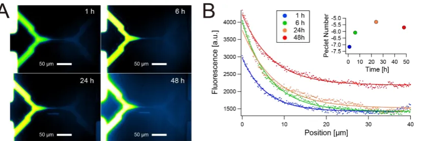
We were able to maintain the concentration gradient of test substances inside or at the exit of the thin microchannel for days. Figure 4A shows an example of concentration gradients of fluorescent dye (Alexa Fluor 488) after the dye solution was added the Test Substances Channel inlet and outlet
(Figure 1C). By making a slight backflow condition within a H-shaped channel (i.e. the inlet/outlet of Cell Channel were pressurized more than that of Test Substance Channel), the gradient of fluorophore remained constant in the thin channel over a long period of time. We did not observe significant changes in gradients in the order of 10 minutes, and as shown in Figure 4A and 4B, only a small change in gradient is observed between 6 h and 24 h.Figure 4B shows that a distinct gradient was maintained in the thin channel for at least 48 h. If there was no pressure difference between the Test Substance Channel and the Cell Channel, the fluorophore diffused much more rapidly and a gradient disappeared quickly.
The conventional model of one-dimensional diffusion from a constant point source, Equation (3), explains the rapid disappearance of concentration gradient within pure diffusion conditions.
𝐶(𝑥, 𝑡) = (𝐶
max− 𝐶
min)erfc (
𝑥
2√𝐷(1 + 𝜅Pe
w2)𝑡
) + 𝐶
min (3)where 𝐷 is the molecular diffusion coefficient of the fluorophore (435 μm2/s for Alexa Fluor 488[14]) , Pew Peclet number defined using the width as relevant length scale, 𝜅 the factor of sidewall and is
≈0.0035 for parabolic cross-section[15]. When we define the concentration at the diffusion front as 0.9(𝐶max− 𝐶min), and even if we ignore the effect of dispersion in channel width direction (i.e. Pew=
0), the predicted value of diffusion front transit time was only 116.5 s for the 40 µm length. More Pew
gives shorter transit time.
Although thinning of microchannel decreases Pew, it is not sufficient to extend the transit time
to the order of days. Applying backpressure is necessary for long-term maintenance of concentration gradient. Although we did not directly observe the backflow under a microscope, the negative values of Peclet numbers calculate with Equation (3) (Figure 4B) indicate the existence of backflow. While Equation (3) assumes static conditions and constant concentration at the point source, it well fitted to the actual gradients. Thin channel may contribute to this good fit because large flow resistance of the thin channel slows down the backflow rate close to static condition, and the effect of small inflow on the source concentration is negligible.
Our H-shaped gradient generator with a thin channel has appropriate flow resistance and satisfies both rapid introduction of test substance and long-term maintenance of gradients simultaneously. While maintaining gradient for two days would be sufficient to test the effect of gradient to cells such as chemotaxis, the user can extend or shorten the diffusion in the thin channel by adjusting the pressure difference between two channels at the ends of the thin channel.
3.3. Guided Axon Elongation
Using a long-lasting concentrate gradient as shown in Figure 4, we examined the long-term effect of nerve growth factor (NGF) gradient on primary DRG neurons cultured in the H-shaped microfluidic channel. NGF is known to contribute to axon elongation, guidance and survival. Therefore, we demonstrated axon elongation towards the NGF source though the thin channel.
viability. Combining an appropriate coculture system to this H-shaped channel may enable single DRG cell survival and eventually single axon separation on chip.
4. Conclusions
We have demonstrated the fabrication of microfluidic channels with various cross-sectional sizes, ranging from 2–6000 µm2 using a simple photo- and softlithographic method. 185 nm diffused UV from a commercially available ozone lamp successfully patterned SU-8 photoresist into thin (2 µm-high) and smooth bell-shaped microfluidic channel features at low cost. In this technique, only process which is unusual for conventional photolithography/soft lithography was sputter coating of Cr on a fused silica wafer. The process, however, can be replaced to purchasing a mask blank.
These thin, H-shaped channels in PDMS microfluidic chips successfully generated visible local gradients because of slow diffusion controlled by Laplace pressures. Since the chip fabrication and fluidic control are simple enough to be implemented by non-experts, this mixed-height microfluidic chip could provide opportunities for a wide range of biomedical experiments and diagnostics investigating cellular response in microscale physicochemical systems, such as axon guidance.
Author Contributions: conceptualization, N.F. and M.Tanaka; methodology, N.F. and M.Tanaka.; software, N.F.; validation, N.F.; formal analysis, N.F. and M.Tamura.; investigation, N.F., T.O. and M.Tamura.; resources, N.F. and M.Tanaka; data curation, N.F.; writing—original draft preparation, N.F., T.O. and M.Tamura.; writing—review and editing, N.F.; visualization, T.O. and M.Tamura.; supervision, N.F.; project administration, N.F.; funding acquisition, M.Tanaka.
Funding: This research was funded by Strategic Research Foundation at Private Universities supported by Japanese Ministry of Education, Culture, Sports, Science and Technology (MEXT), grant number S0801023.
Figure 5. Axon elongation of primary nerve (dorsal root ganglion: DRG) cells from chick embryo in culture on the microfluidic chip. A) Phase contrast images of axon elongation from the inlet of cell channel (bottom left), thick channel 1, thin channel, thick channel 2, and the source of nerve growth factor (NGF) (bottom right). Arrows denote the tip of an outgrowth axon. B) Time evolution of the length of axons cultured on six different chips from the same mold. Dots above
Acknowledgments: We thank Ms. Mika Miyashita, and Ms. Saori Inomata at Tokyo Denki University for support with fluorescence microscopy and primary neuronal cell culture. We also thank Dr. Tomofumi Ukai and the Bio Nano Electronics Research Centre of Toyo University for the height field measurement using laser confocal microscopy, and Dr. Nobuyuki Takei at Niigata University for donation of neural growth factors.
Conflicts of Interest: The authors declare no conflict of interest.
References
1. Chung, B.G.; Choo, J. Microfluidic gradient platforms for controlling cellular behavior. Electrophoresis 2010, 31, 3014-3027, doi:10.1002/elps.201000137.
2. Ahmed, T.; Shimizu, T.S.; Stocker, R. Microfluidics for bacterial chemotaxis. Integr Biol (Camb) 2010, 2, 604-629, doi:10.1039/c0ib00049c.
3. Ben-Yakar, A.; Chronis, N.; Lu, H. Microfluidics for the analysis of behavior, nerve regeneration, and neural cell biology in C. elegans. Current Opinion in Neurobiology 2009, 19, 561-567, doi:http://dx.doi.org/10.1016/j.conb.2009.10.010.
4. Weibel, D.B.; Whitesides, G.M. Applications of microfluidics in chemical biology. Current Opinion in Chemical Biology 2006, 10, 584-591, doi:http://dx.doi.org/10.1016/j.cbpa.2006.10.016.
5. Whitesides, G.M. Cool, or simple and cheap? Why not both? Lab on a chip 2013, 13, 11-13.
6. Miller, R.G.; Phillips, R.A. Separation of cells by velocity sedimentation. Journal of Cellular Physiology 1969, 73, 191-201, doi:10.1002/jcp.1040730305.
7. Fakhr, O.; Altpeter, P.; Karrai, K.; Lugli, P. Easy Fabrication of Electrically Insulating Nanogaps by Transfer Printing. Small 2011, 7, 2533-2538, doi:10.1002/smll.201100413.
8. Duffy, D.C.; McDonald, J.C.; Schueller, O.J.; Whitesides, G.M. Rapid Prototyping of Microfluidic Systems in Poly(dimethylsiloxane). Anal Chem 1998, 70, 4974-4984, doi:10.1021/ac980656z.
9. Linder, V.; Wu, H.; Jiang, X.; Whitesides, G.M. Rapid prototyping of 2D structures with feature sizes larger than 8 microm. Anal. Chem. 2003, 75, 2522-2527.
10. López-Romero, D.; Barrios, C.A.; Holgado, M.; Laguna, M.F.; Casquel, R. High aspect-ratio SU-8 resist nano-pillar lattice by e-beam direct writing and its application for liquid trapping. Microelectronic Engineering 2010, 87, 663-667, doi:http://dx.doi.org/10.1016/j.mee.2009.09.007.
11. Huh, D.; Mills, K.L.; Zhu, X.; Burns, M.A.; Thouless, M.D.; Takayama, S. Tuneable elastomeric nanochannels for nanofluidic manipulation. Nat Mater 2007, 6, 424-428, doi:10.1038/nmat1907.
12. Park, S.M.; Huh, Y.S.; Craighead, H.G.; Erickson, D. A method for nanofluidic device prototyping using elastomeric collapse. Proc Natl Acad Sci U S A 2009, 106, 15549-15554, doi:10.1073/pnas.0904004106.
13. Futai, N.; Gu, W.; Takayama, S. Rapid Prototyping of Microstructures with Bell-Shaped Cross-Sections and Its Application to Deformation-Based Microfluidic Valves. Adv. Mater. 2004, 16, 1320-1323, doi:10.1002/adma.200400595.
14. Petrášek, Z.; Schwille, P. Precise Measurement of Diffusion Coefficients using Scanning Fluorescence
Correlation Spectroscopy. Biophysical Journal 2008, 94, 1437-1448, doi:10.1529/biophysj.107.108811.
15. Ajdari, A.; Bontoux, N.; Stone, H.A. Hydrodynamic dispersion in shallow microchannels: the effect of cross-sectional shape. Anal Chem 2006, 78, 387-392, doi:10.1021/ac0508651.