TOSHIBASYSTEM PRACTICES
OIGITALKEYTELEPHONESYSTEMS
INSTALLATION-INTRODUCTION
SECTION
100-816-201
MARCH
1993
INSTALLATION
Chapter One
-
Introduction
Chapter Two
-
Site Requirements
Chapter Three -
System Configuration
Chapter Four
-
DK8 KSU and PCB Installation
Chapter Five
-
DK16 KSU and PCB Installation
Chapter Six
-
Station Apparatus Installation
Chapter Seven -
Peripheral Installation
Chapter Eight -
Wiring Diagrams
TOSHIBASYSTEM PRACTICES
DIGITALKEYTELEPHONESYSTEMS
INSTALLATION-INTRODUCTION
SECTION lOO-816-201
MARCH1993
INSTALLATION
CHAPTER ONE
PARAGRAPH
1 2 3 3.10 3.20 3.30 3.40 3.50 4 4.10
INSTALLATION-INTRODUCTION SECTION lOO-816-201
MARCH1993
TABLEOFCONTENTS
SUBJECT
PURPOSE . . .
ORGANIZATION . . .
REFERENCE DOCUMENTATION . . .
General Description . . .
Programming . . .
User Guides . . .
Fault Finding Procedures . . .
Remote Maintenance and Administration . . .
SYSTEM MNEMONICS/TERMS . . .
Use of Notes, Important Notes, Cautions, and Warnings . . .
PAGE
INSTALLATION-INTRODUCTION
SECTION
100-816-201
MARCH 1993
1 PURPOSE
1.00 The purpose of this section is to provide
detailed step-by-step instructions for installing the
STRATA DK8 and STRATA DK16 systems.
1.01 This chapter provides an overview of the
entire installation section, and includes a list of
reference documentation that supports the in-
stalled system; a list of system mnemonics is also
provided.
2 ORGANIZATION
2.00 This manual is organized in modular chap-
ters for easy removal and replacement of updated
materials. The chapters are as follows:
Chapter One
- Introduction
Chapter Two
- Site Requirements
Chapter Three - System Configuration
Chapter Four
- STRATA DK8 KSU and PCB
Installation
Chapter Five
- STRATA DK16 KSU and PCB
Installation
Chapter Six
- Station Apparatus Installation
Chapter Seven - Peripherals Installation
Chapter Eight
- System Wiring and Main Dis-
tribution Frame Arrangements
3 REFERENCE
DOCUMENTATION
telephones, standard telephones, direct station
selection consoles, add-on modules and data in-
terface units.
3.40 Fault Finding Procedures: Hardware trou-
bleshooting and diagnostic information presented
in flowchart form.
3.50 Remote Maintenanceand Administration:
Programming and maintenance procedures spe-
cially adapted for remote maintenance and admin-
istration terminal use. Detailed, step-by-step in-
structions are provided, complete with the terminal
responses.
4 SYSTEM MNEMONICS/TERMS
4.00 Mnemonics are used to identify the system’s
hardware, operation, and features. The following
alphabetical listing describes the mnemonics used
in this manual.
ADM: Add-on Module-A telephone upgrade that
provides 20 Direct Station Selection (DSS) but-
tons with busy LED indication on STRATA DK16
and 10 DSS buttons plus 8 speed dial buttons
(one for every station), one night transfer and
one all call page button on STRATA DK8. Can
be installed on any or all 2000-series Digital
Telephones in the system. Attaches to the tele-
phone and uses the same port assigned to the
telephone. ADM buttons are fixed and cannot
be changed in system programming.
3.00 The STRATA DK8 and DK16 digital key
systems are supported by the following comple-
ment of reference documentation:
3.10 General Description: An overview of the
STRATA DK8 and DK16 systems and their fea-
BPS: Bits Per Second-Unit of measure that re-
fers to the transmission speed (baud rate) of
electronic signals. It is used when describing
data interface unit and modem operation.
tures.
3.20 Programming:
Detailed step-by-step in-
structions on how to enter data in the System
Record sheets, and how to program the system
from the completed System Record Sheets. LCD
responses are included to provide clear guidance
for the programmer.
3.30 User Guides: Detailed step-by-step guides
on how to operate digital telephones, electronic
CO: Central Office-The
facility which houses
switching equipment that provides telephone
service (CO lines, Centrex lines, etc.) for the
immediate geographical area.
INSTALLATION-INTRODUCTION
SECTION
100-816-201
MARCH 1993
CODECs: Coder/Decoders-&emiconductors that
allow the system to process analog-to-digital
and digital-to-analog conversions.
DDCB: Digital Door Phone/Lock Control Unit-A
peripheral hardware unit that can be connected
to designated digital telephone circuits/ports.
The DDCB has three interfaces, two of which
are dedicated to door phones (MDFB), and one
that can be connected to a MDFB or a door lock.
DISA: Direct Inward System Access-A
feature
available for CO lines that allows an outside
party to access a STRATA system’s internal
stations or outgoing CO lines without going
through an operator or automated attendant. An
optional security code and/or
account
codes
may be set to prevent unauthorized access to
outgoing CO lines for through system calling.
DK: Digital Key.
DKSU8: Key Service Unit (STRATA DK8 only)-
The standard key service unit which includes
the system’s motherboard, power supply, two
CO line circuits, four digital telephone circuits,
relay service, and interface for Music-on-hold
(MOH)/Background Music (BGM) and External
Page.
DKSUB16: Base Key Service Unit (STRATA DK16
only)-The standard key service unit which in-
cludes the system’s motherboard, power sup-
ply, four CO line circuits, eight digital telephone
circuits, relay service, and interface for Music-
on-hold (MOH)/Background Music (BGM) and
External Page.
DKSUE16: Expansion Key Service Unit (STRATA
DKI 6 only)-The optional key service unit which
has four universal slots that can support CO line,
station, and external option printed circuit boards
that are compatible with the larger STRATA DK
systems (DK24/DK56/DK96).
DSS: Direct Station Selection Console (STRATA
DK16 only)-A console designed to facilitate
the processing of a heavy load of incoming calls.
There are two types of DSS consoles: the DDSS
console and the HDSS console. The chief differ-
ence between them is that the DDSS console
can be connected to designated digital tele-
phone circuits, while the HDSS console can
only be connected to designated electronic tele-
phone circuits.
DTMF: Dual-tone Multi-frequency-Push-button
dialing.
DVSU: Off-hook Call Announce Upgrade-A sub-
assembly that allows a digital telephone to re-
ceive Off-hook Call Announce.
EOCU: Off-hookCall Announce Upgrade (STRATA
DK16 only)-An optional subassembly to the
ElectronicTelephone Interface Unit PCB (PEKU)
or Standard/ElectronicTelephone Interface Unit
(PESU) that provides support for electronic tele-
phones that must receive Off-hook Call An-
nounce. Electronic telephones that must re-
ceive Off-hook Call Announce must also have
an HVSU2subassemblyorthecombined HVSU/
HVSI subassemblies.
FCC: Federal Communication Commission-The
telecommunication industry’s federal regulatory
agency. All Toshiba hardware is FCC listed or
approved.
HESB: External Speaker Box-A speaker/ampli-
fier that can be configured with the system and
telephones to provide a variety of functions.
HESC-65A: A cable that connects an HHEU-
equipped digital telephone or electronic tele-
phone to an HESB for a Loud Ringing Bell .
HHEU: Loud Ringing Bell/Headset Jack Interface
Upgrade-Asmall subassembly for use inside a
digital telephone or a 6500-series electronic
telephone that allows a speaker (HESB) and/or
a headset to be installed with the station.
HVSU2: Off-hook Call Announce Upgrade-A
INSTALLATION-INTRODUCTION SECTION lOO-816-201
MARCH 1993 IMDU: Remote Maintenance Modem Interface
Unit (STRATA DK16 only)-A subassembly installed on a PIOU or PIOUS PCB in the op- tional DK16 Expansion Key Service Unit that allows the system to be connected with a remote maintenance/administration terminal.
KCDU: CO Line/Digital Telephone Interface Unit (STRATA DK16 only)-Optional printed circuit board providing two loop start CO line circuits and four digital telephone circuits that can be installed in the Expansion Unit. The digital tele- phone circuits support the same devices as the PDKU except for the DDSS console.
KCOU: CO Line Interface Unit (STRATA DK16 only)-Factory-installed printed circuit board that comes standard with the Base Key Service Unit to provide four loop start CO line circuits. Avail- able as a spare unit for field replacements. KFCU: (STRATA DK16 only) Option feature car-
tridge that plugs into the Base Unit to provide feature upgrades to DK16.
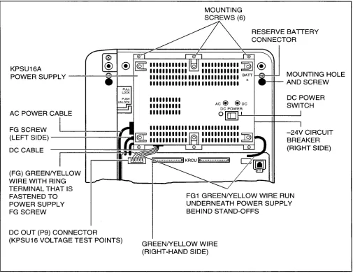
KPSU16: (STRATA DK16 only) Power supply that comes factory-installed in the Base Key Service Unit. This power supply provides power to the entire system, in its standard and expanded configurations. Available as a spare unit for field replacements.
K4RCU: (STRATA DK16 only) Optional unit that can be installed in the Base Key Service Unit to provide a 4-circuit Dual-tone Multi-frequency receiver for CO lines and standard telephones. It also provides busy tone detection for Auto Busy Redial.
KSTU: Standard Telephone Interface Unit (STRATA DK16 only)-Optional printed circuit board that can be installed in the Base Key Service Unit to provide four standard telephone circuits.
LCD: Liquid Crystal Display-Display used for messaging, identification, and status that ap- pears on some digital and electronic telephones.
LED: Light Emitting Diode-Status indicators lo- cated on printed circuit boards, digital telephones, and electronic telephones.
LSI: Large Scale Integration-Related to circuit design technology. STRATA DK8 and STRATA DK16 printed circuit boards use LSI circuit de- sign.
MDF: Main Distribution Frame-The wiring frame usually located in a phone closet.
MDFB: Door Phone Box-A peripheral two-way speaker box option. Each MDFB connects to a DDCB. A DDCB can support as many as three MDFBs.
OCA: Off-hook Call Announce.
PBX: Private Branch Exchange-lndustry-stan- dard term which refers to a telephone switch, usually on-premises, which serves an individual company, and is connected to a public tele- phone exchange through the CO.
PCB: Printed Circuit Board.
PCM: Pulse Code Modulation-A widely used form of digital telephone switching.
PCOUl: CO Line Interface Unit (STRATA DK16 only)-A printed circuit board that can be in- stalled in the optional Expansion Key Service
Unit to provide the system with four loop start CO lines circuits.
PCOU2: (STRATA DK16 only) The PCOU2 is a direct replacement for the PCOUl. Their fit/ form/function is identical; however, for manu- facturing reasons, the PCOUl was phased out in favor of the PCOU2.
INSTALLATION-INTRODUCTION
SECTION
100-816-201
MARCH 1993
Stand-alone Data Interface Units (PDIU-DSs). The PDIU-DI is also used to provide personal computer access to outside dial-up data ser- vices and/or bulletin boards.
NOTE:
The PDIU-DI and the PDIU-Dl2 are identical, except that the PDIU-DI attaches to lOOO- series Digital Telephones, while the PDIU- 012 attaches to 2000-series Digital Tele- phones.
PDIU-DS
: Stand-alone Data Interface Unit-Used for modem pooling, printer sharing, and access to a host/mainframe computer.PDKUI
: DigitalTelephone Inter-face Unit (STRATA DK16 only)-A printed board that can be in- stalled in the optional Expansion Key Service Unit to provide the system with eight digital telephone circuits. In addition to digital tele- phones, the PDKU can support data interface units (Stand-alone and Integrated), a digital DSS console (DDSS), and a digital door phone/ lock control unit (DDCB).PDKU2:
DigitalTelephone Interface Unit (STRATA DK16 only)-Provides same function as the PDKUl, except that the PDKUl can only sup- port data interface units on Circuits 1 w 7, while the PDKU2 can support data interface units on Circuits 1 w 8.PEKU:
Electronic Telephone Interface Unit (STRATA DK16 only)-An optional PCB that provides the system with eight electronic tele- phone circuits, which can support electronic telephones, a Background Music source, an electronic DSS console (HDSS), and an ampli- fier for two CO line conference calls.PESU:
Standard/Electronic Interface Unit (STRATA DK16 only)-A printed circuit board with two standard telephone circuits and four electronic telephone circuits that can be installed in the optional Expansion Key Service Unit. The elec- tronic telephone circuits can support the same devices as the PEKU, except for the HDSS console. The standard telephone circuits cansupport the same single-line devices as the KSTU and the PSTU.
PFT:
Power Failure Transfer Interface-Dedicated standard telephone interface located on the motherboard in the DKSUBI 6 (STRATA DK16) or DKSU8 (STRATA DK8) to provide emergency service during a system power failure.PIQU:
Option Interface Unit (STRATA DKl Gorily)- A printed circuit board that can be installed in the optional Expansion Key Service Unit to provide support and/or circuit interface for optional hard- ware peripherals and upgrades.PIOUS:
(STRATA DK16 only) The same as the PIOU, except the PIOUS has one external pag- ing interface zone, while the PIOU has four. NOTE:The system cannot support the PIOU and PIOUS simultaneously. Only one or the other can be installed.
PORT:
There are two types of ports: physical and logical. A physical port is an actual station circuit location; a logical port is the set of characteris- tics-features, station intercom number, etc.- assigned to the physical port. Logical ports are mobile. They can be moved from one physical port to another.PBTC:
A Toshiba-supplied cable used to connect customer-supplied batteries to the power sup- ply in the DKSUB for emergency reserve power.PPTC:
(STRATA DK16 only) A Toshiba-supplied adapter that is used to connect the modular SMDR and/or maintenance ports to the DB-25 connector of a printer, terminal, modem or call accounting machine. The SMDR/Maintenance (TTY) port is located on the optional QSMU PCB (STRATA DK8), or PIOU or PIOUS PCB (STRATA DK16).INSTALLATION-INTRODUCTION
SECTION
100-816-201
MARCH 1993
QSTU:
Standard Telephone Interface Unit(STRATA DK8 only)-Optional printed circuit board that can be installed in the KSU to provide two standard telephone circuits.
provide interface for eight standard telephones or optional hardware peripherals (voice mail devices, fax machine, Background Musicsource, etc).
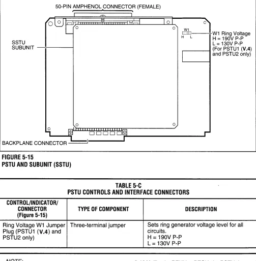
PSTU2:
Standard Telephone interface Unit (STRATA DK16 only)-Provides the same function as the PSTU with the addition of a switch to select high or low ringing generator voltage.QCDU:
CO Line/Digital Telephone Interface Unit (STRATA DK8 only)-Optional printed circuit board providing one loop start CO line circuit and two digital telephone circuits that can be installed in the KSU. A maximum of two QCDUs may be installed in the DK8.QCNU:
Conference Unit (STRATA DK8 only)- Standard factory-installed printed circuit board provides two conference circuits that can be installed in the KSU. The PCB allows two si- multaneous conferences: four parties for the first, and three parties for the second simulta- neous conference.QPSU:
(STRATA DK8 only)-Power supply that comes factory-installed in the KSU. This power supply provides power to the entire system. Available as a spare unit for field replacements.QRCU:
Optional printed circuit board that can be installed in the KSU to provide a 3-circuit Dual- tone Multi-frequency receiver for DISA CO lines and standard telephones. It also provides busy tone detection for Auto Busy Redial.RAM:
Random Access Memory-Refers to the type of system memory that holds individual system configuration and feature programming. RAM is read/write memory, and can be easily revised in programming.ROM:
Read Only Memory-Refers to the type of system memory that holds static software that comprises the mechanics of the features’ func- tions. ROM is only revised by Toshiba software engineers.4.10 Use of Notes, Important Notes, Cautions,
and Warnings
4.11 Notes call attention to specific items to elabo- rate, or to refer the reader to other information. 4.12 Important Notes are used when the informa- tion is considered to be very important.
4.13 Cautions call attention to the possibility of equipment being damaged if the instructions are not followed closely.
4.14 Warnings are used when the given tasks involved could cause the possibility of personal injury or death to the technician.
TOSHIBASYSTEM PRACTICES OIGITALKEYTELEPHONE
SYSTEMS
INSTALLATION-SITEREQUIREMENTS SECTION 100-816-202
MARCH1993
INSTALLATION
CHAPTER TWO
PARAGRAPH
SUBJECT
PAGE
1 GENERAL ... 2-1 2 INPUT POWER REQUIREMENTS ... 2-1 3 SITE CONSIDERATIONS ... 2-1 3.00 Clearance and Location Requirements ... 2-1 3.10 Electrical/Environmental Requirements and Characteristics ... 2-2 4 GROUNDING REQUIREMENTS ... 2-2 4.10 Third Wire Ground Test ... 2-2 4.20 Alternate or Additional Ground ... 2-4 INSTALLATION-SITE REQUIREMENTS
SECTiON lOO-816-202 MARCH1993
TABLEOFCONTENTS
TABLE LIST
TABLE
TITLE
PAGE
2-A SUMMARY OF ELECTRICAL/ENVIRONMENTAL CHARACTERISTICS . . . 2-3
FIGURE LIST
FIGURE
2-1 2-2 2-3 2-4
TITLE
PAGE
DK8 BASE KEY SERVICE UNIT AND HPFB MINIMUM CLEARANCE
REQUIREMENTS . . . 2-1 BASE KEY SERVICE UNIT MINIMUM CLEARANCE REQUIREMENTS . . . 2-1 DK16 COMBINED BASE AND EXPANSION KEY SERVICE UNIT
INSTALLATION-SIJE
REQUIREMENTS
SECTION
100-816-202
MARCH 1993
1 GENERAL
1
.OO This chapter defines the installation site re- quirements necessary to ensure a proper operat- ing environment for the STRATA DK8 and DK16. Also included are grounding requirements.2 INPUT POWER REQUIREMENTS
2.00 The system requires an input power source of 117VAC nominal (85VAC - 135VAC), 50/60 Hz, 15 amps. The AC outlet is recommended to be dedicated and unswitched, with a solid third wire ground (refer to Paragraph 4). This is to eliminate interference from branch circuit motor noise or the like, and to prevent accidental power-off.2.01 To avoid accidental power turn-off, it is recom- mended that an ON/OFF wall switch not be used on this dedicated AC circuit.
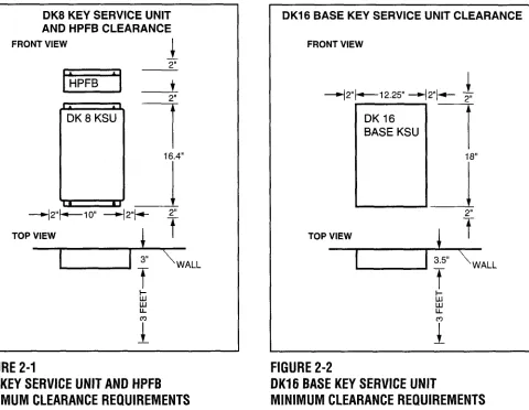
DK8 KEY SERVICE UNIT AND HPFB CLEARANCE
FRONT VIEW
1
-42”+-10” 42”/4- 2”
Top*ALL
FIGURE
2-1
DK8 KEY
SERVICE
UNIT AND HPFB
MINIMUM CLEARANCE
REQUIREMENTS
2.02 An option Reserve Power Battery and Charger (HPFB) is available for use with the STRATA DK8 to serve as a power failure backup. For the STRATA DKl6, a reserve power source (two customer-supplied 12-volt batteries) may be connected to the system to serve as a power failure backup.
3 SITE CONSIDERATIONS
3.00 Clearance and Location Requirements
3.01
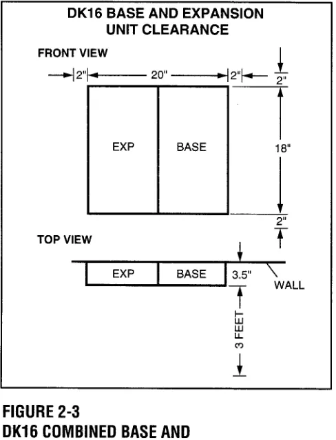
The key service units must be wall mounted. Figure 2-1 shows the minimum clearance require- ments for the STRATA DK8 system, and includes the recommended mounting location and clear- ance requirements for the optional HPFB. Figures 2-2 (Base Key Service Unit) and 2-3 (Base and Expansion Key Service Unit together) show the minimum clearance requirements for the standardDK16 BASE KEY SERVICE UNIT CLEARANCE
FRONT VIEW
+2”+-12.25” 42”+-- -
TOP VIEW
1
,
fI
WALLL
FIGURE
2-2
DK16 BASE
KEY
SERVICE
UNIT
INSTALLATION-SITE REQUIREMENTS SECTION 100-816-202
MARCH 1993
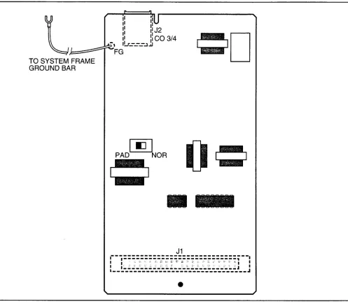
DK16 BASE AND EXPANSION UNIT CLEARANCE
FRONT VIEW
-4 2+--- 20” ---4 2”+- 2”
TOP VIEW
t
I
EXP BASE 3.5” \WALL
FIGURE 2-3
DK16 COMBINED BASE AND
EXPANSION KEY SERVICE UNIT
MINIMUM CLEARANCE REQUIREMENTS
and optioned STRATA DK16 system. Refer to Chapter 4 for DK16 key service unit wall mounting instructions.
4.00 The systems require a solid earth ground for proper operation. Failure to provide ground may lead to confusing trouble symptoms and, in ex- treme cases, system failure. The AC power cord contains a conductor for the “third wire ground” provided by the commercial power outlet. The third-wire ground should be the only ground nec- essary for the DK8/DK16; this ground must origi- nate at the buildings main power distribution panel and have a solid connection to earth ground. (Figure 2-4)
4.10 Third Wire Ground Test 3.02 The following conditions must be considered
when selecting a location forthe key service unit(s): The location MUST BE:
l Dry and clean l Well ventilated l Well illuminated l Easily accessible
4.11 Test the “third wire ground” for continuity by either measuring the resistance between the third prong terminal (earth ground) and a metal cold water pipe (maximum: 1 ohm), or by using a commercially available earth ground indicator. If neither procedure is possible, perform the follow- ing earth ground test procedure:
WARNING!
The location MUST NOT BE:
Hazardous voltages that may cause death
l Subject to extreme heat or cold
or injury are exposed during the folio wing
l Subject to corrosive fumes, dust, or other air-test. Use great care when working with AC
borne contaminants
power line voltage.
l Subject to excessive vibration
l Next to television, radio, office automation, or
high frequency equipment
1) Obtain a suitable voltmeter, and set it for a possible reading of up to 250 VAC.
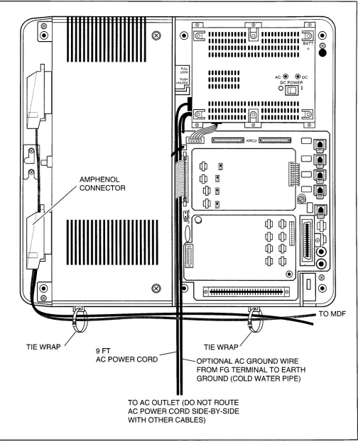
3.03 If reserve power is to be installed for the STRATA DK16, the batteries will require a well- ventilated location close (within nine feet) to the DKSUB16 (the optional Toshiba-supplied battery cable is 9 feet in length). The STRATA DK8 reserve battery (HPFB) should be mounted di- rectly above the DKSU8 as shown in Figure 2-l. 3.10 Electrical/Environmental Requirements and Characteristics
3.11 The electrical/environmental requirements and characteristics for each system are provided in Table 2-A.
INSTALLATION-SITE
REQUIREMENTS
SECTION lOO-816-202
MARCH1993
TABLE
2-A
SUMMARY
OF ELECTRICAL/ENVIRONMENTAL
CHARACTERISTICS
GENERAL Primary power
Input AC AC frequency Power
Environmental specifications
Operating temperature Operating humidity Storage temperature
Power supply
DC voltage output specification
Battery charger characteristics
(DK16 only)
QSTU, KSTU, PSTU or PESU (circuits 1 & 2)
Ring voltage Ringing capability
85 - 135VAC 50/60 Hz
DK8-46 watts maximum, DK16-75 watts maximum 32 - 104°F (0 - 40°C)
20 - 80% relative humidity without condensation - 4 - 158°F (-20 - 70°C)
DK16 DK8
-24VDC: (-26.3 - -27.8VDC) +24VDC: (+26.3 - +27.8VDC) +5VDC: ( +4.5 - +5.5VDC) +5VDC: ( +4.5 - +5.5VDCj -5VDC: ( -4.5 - -5.5VDC) Note: +5V converter
on KSU PCB Charger: current limiting
Nominal float voltage: 2.275 volts/cell Charge current: 0.7 amps maximum
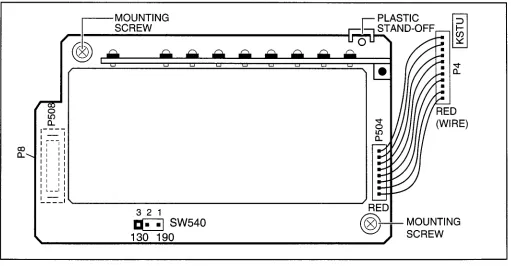
Battery discharge cut-off voltage: 20.5 + 0.5VDC Square wave output with high/low option jumper: Low position, 130 + 20VDC peak-to-peak (no-load) High position, 190 f 25VDC peak-to-peak (no-load) Two ringers maximum per circuit, high or low position
GROUND 1 THIRD WIRE GROUND \ TO AC POWER CORD
ELECTRICAL SYSTEM GROUND
8 FG
FIGURE
2-4
KSU GROUNDING
DIAGRAM
2) Connect the meter probes between the two main AC voltage terminals (white and black wires) on the wall outlet. The reading obtained should be between 100 - 120 VAC.
3) Move one of the meter probes to the third terminal (green wire ground). Either the same reading or a reading of zero volts should be obtained.
4) If the reading is zero volts, leave one probe on the ground terminal and move the other probe to the second voltage terminal.
CAUTION!
If a reading of zero volts is obtained on
both voltage terminals (white wire to green
wire, black wire to green wire), the outlet is
not properly grounded. Omit steps 5 and
INSTALLATION-SITE
REQUIREMENTS
SECTION
100-816-202
MARCH 1993
5)
6)
If a reading of zero volts on one terminal, and a reading of 100 - 120 VAC on the other terminal is obtained, remove both probes from the outlet.
Set the meter to the “OHMS/Rxl”scale. Place one probe on the ground terminal, and the other probe on the terminal that produced a
reading of zero volts. The reading should be less than 1 ohm.
4.20 Alternate or Additional Ground
4.21 If the “third wire” AC ground can not practi- cally be improved or if extreme motor noise or other disturbance causes system malfunction, or if local area lightning storms exist, a separate direct ground may be warranted.
4.22 Connect a separate earth ground from a cold water pipe or earth grounding rod directly to the FG screw terminal on the DK8/DK16 power supply. See Figure 4-5 of
Section 100-816-204
(for STRATA DK8) or Figure 5-8 ofSection 100-816-
205 (for STRATA DK16).
CAUTION!
If the reading is more than one ohm, then
the outlet is not adequately grounded.
7) If the above tests show the outlet is not properly grounded, the condition should be corrected
TOSHIBA
SYSTEM
PRACTICES
DIGITAL
KEY
TELEPHONE
SYSTEMS
INSTALLATION-CONFIGURATION SECTION lOO-816-203 MARCH1993
INSTALLATION
CHAPTER THREE
1 INTRODUCTION
1 .OO This chapter offers guidelines and consider- ations on how to configure a STRATA DK8/DK16 system, which can support a wide variety of sta- tions and peripherals.
2 SYSTEM CAPACITY
2.00 Total System Capacity
2.01 The STRATA DK8/DK16 systems have a modular design which allows them to support a number of station and CO line configurations. The main component of each system is the Key Ser- vice Unit. The DK8 KSU can have up to IO stations and four CO lines. The DK16 Base Key Service Unit can have up to 12 stations and four CO lines. An Expansion Key Service Unit can be added to the DK16 to increase the station capacity to 20 and the CO line capacity to eight. Station and CO line configurations are shown in Table 3-A (for DK8) and Table 3-B (for DK16).
2.10 The DK8 Key Service Unit
2.11 Station and CO Lines. The DK8 Key Service Unit comes standard with four digital telephone circuits (ports) and two CO line circuits (Table 3-C). An optional printed circuit board called the QCDU can be added to the KSU to provide one CO line circuit and two digital telephone circuits. A maximum of two QCDUs may be added to provide a total of four additional digital telephone circuits and two additional CO line circuits. Another op- tional printed circuit board called the QSTU can be added to the DK8 KSU to provide two standard telephone circuits.
2.12 Peripherals. The DK8 Key Service Unit can support a number of peripherals, which are not considered as stations and do not affect the maxi- mum station and CO line capacities. A customer- supplied Music-on-hold source, optional reserve power battery and charger, a customer-supplied emergency standard telephone for system power failure occurrences and an amplifier with speaker for paging and night ringing can all be connected to the Key Service Unit (Table 3-C). A relay contact is also provided to control one of the following
INSTALLATION-CONFIGURATION SECTION 100-816-203
MARCH 1993 peripherals: Music-on-hold source, night bell, or page amplifier mute control.
2.20 The DK16 Base Key Service Unit
2.21 Station and CO Lines. The DKI 6 Base Key Service Unit comes standard with eight digital telephone circuits (ports) and four CO line circuits (Table 3-D). An optional printed circuit board called the KSTU can be added to the unit to provide four standard telephone circuits (ports).
2.22 Peripherals. The DK16 Base Key Service Unit can support a number of peripherals, which are not considered as stations and do not affect the maximum station and CO line capacities. A customer-supplied Music-on-hold source, cus- tomer-supplied separate background music source, customer-supplied reserve power batter- ies, a customer-supplied emergency standard telephone for system power failure occurrences and an amplifier with speaker for paging and night
ringing can all be connected to the Base Key Service Unit (Table 3-D). A relay contact is also provided to control one of the following peripher- als: Music-on-hold source, night bell, or Page Amplifier mute control.
2.30 The DK16 Expansion Key Service Unit 2.31 Station and CO Lines. The optional DK16 Expansion Key Service Unit has four universal slots which can support a maximum of four CO lines and eight stations. Printed circuit boards (PCBs) that support CO lines and can be installed in the Expansion Unit are the PCOU and KCDU (Table 3-E). PCBs that can support stations and be installed in the Expansion Unit are the PDKU, PEKU, PSTU, PESU, and KCDU.
INSTALLATION-CONFIGURATION
SECTION lOO-816-203
MARCH1993
TABLE
3-A
DK8 CD LINE/STATION
CONFIGURATION
GUIDE
EQUIPMENT
KSU = Key Service Unit .2 CO Lines/4 digital circuits) CO = Central Office
QCDU = Optional PCB (1 CO line/2 digital circuits) DKT = Digitai Telephone
QSTU = Optional PCB (2 standard circuits) SLT = Standard Telephone
CONFIGURATION CO
LINES BY STATION COs DKTs SLTs EQUIPMENT
2 by 4 2 4 KSU
2 by 6 2 4 2 KSU + QSTU
3 by 6 3 6 KSU + QCDU
3 by 8 3 6 2 KSU + QCDU + QSTU
4 by 8 4 8 KSU + QCDU + QCDU
4bylO 4
a
2 KSU + QCDU + QCDU + QSTUTABLE
3-B
DK16 CD LINE/STATION
CONFIGURATION
GUIDE
(BASE
AND EXPANSION
UNIT)
EQUIPMENT
BU = Base Unit (4 CO lines/8 digital circuits) PSTU = EU option (8 standard circuits)
KSTU = Base Unit Option (4 standard circuits) PCOU = EU option (4 CO lines)
EU = Expansion Unit co = Central Office line
PDKU = EU option (8 digital circuits) DKT = Digital telephone
KCDU = EU option (2 CO lines/4 digital circuits) EKT = Electronic telephone
PEKU = EU option (8 electronic circuits) SLT = Standard telephone
PESU = EU option (2 standard/4 electronic circuits)
CONFIGURATION CO
LINES BY STATION 4 by 8 4by12 4by14 4by16 4by16 4by16 4by18 4 by 20 4 by 20 4 by 20 6by12 6 by 16 8 by 8
a
by128by14 8by16 8by16 8by16 8by18 8by20
a
by 208 by 20 8 by 20
cos DKTs EKTs SLTs EQUIPMENT
4 8 BU
4 8 4 BU + KSTU
4
a
4 2 BU + EU + PESU4 8 8 BU + EU + PSTU
4 8 8 BU + EU + PEKU
4 16 BU + EU + PDKU
4 8 4 6 BU + KSTU + PESU
4 8 8 4 BU + KSTU + EU + PEKU
4 16 4 BU + KSTU + EU + PDKU
4 8 12 BU + KSTU + EU + PSTU
6 12 BU + EU + KCDU
6 12 4 BU + KSTU + EU + KCDU
8 8 BU + EU + PCOU
8 8 4 BU + KSTU + EU + PCOU
8 8 4 2 BU + EU + PCOU + PESU
a
8 8 BU + EU + PCOU + PEKUa
16 BU + EU + PDKU + PCOU8 16 BU + EU + KCDU + KCDU
8 8 4 6 BU + KSTU + EU + PCOU + PESU
8 16 4 BU + KSTU + EU + KCDU + KCDU
8 8 8 4 BU + KSTU + EU + PCOU + PEKU
8 16 4 BU + KSTU + EU + PCOU + PDKU
INSTALLATION-CONFIGURATION SECTION 100-816-203
MARCH1993
TABLE
3-C
DK8 KEY SERVICE
UNIT COMPONENTS
item supports Connector Type Standard Optional
Digital Telephone Circuits (4) l Digital Telephones (with 25pair Amphenol J
or without PDIU-D12 or ADM)
l Stand-alone Data
Interface Units (PDIU-DS)
l Door Phone Lock/Control
Unit (DDCB)
CO Line Circuits (2) 0 Loop Start CO Lines RJll Modular J
Power Failure Transfer Interface l Standard Telephone RJll Modular J
(one)*
Battery Backup Interface l Optional HPFB Battery Proprietary Interface HPFB
(one or two per system) Cable/Connector with cable
Music-On-Hold/BGM Interface l Music-on-hold/BGM RCA Jack J
Source*
600 Ohm page Interface l Amplifier/Speaker RCA Jack J
CO line CKT (l)/ l Digital Telephones (with 25pair Amphenol
Digital Telephone CKT (2) (QCDU) or without PDIU-D12 or
(max. 2 QCDU per system) ADM) J
l Stand-alone Data
Interface Units (PDIU-DS)
l Loop Start CO Line RJll Modular
Standard Telephone l Standard Telephones*
Interface Unit (QSTU) l Other Single-line Devices* 25pair Amphenol
) 2 standard telephone circuits l Fax Machine* J
(1 max.) QSTU per system l Voice Mail Devices
l Alternate BGM source*
DTMF/ABR Tone Receiver l Automatic Busy Redial Internal
(3-Receiver CKT per QRCU ) l Standard telephone ports
. DISA
Control Relay One of the following: 25-pair Amphenol
l Night Relay
l External Page Mute J
l MOH Control Relay
Conference Circuit Interface Unit l 2 Simultaneous Internal
(QCNU) Conferences J
SMDRKTY interface Unit (QSMU) l SMDR Printer*, or 6-pin Modular
(Requires PPTC) l Maintenance Terminal* or (PPTC adaptor)
l Modem*
*Customer supplied equipment not offered by Toshiba Telecommunication Systems Division.
J
INSTALLATION-CONFIGURATION
SECTION lOO-816-203
MARCH1993
TABLE
3-D
DK16 BASE
KEY SERVICE
UNIT COMPONENTS
item
Digital Telephone Circuits (8)
supports Connector Type Standard Optional
0 Digital Telephones (with 25-pair Amphenol J
or without PDIU-D12 or ADM)
l Stand-alone Data
interface Units (PDIU-DS)
l Door Phone Lock/Control
Unit (DDCB)
l Digital Direct Station
Selection Console (DDSS)
CO Line Circuits (4) Loop Start CO Lines RJl 1 Modular J
Power Failure Transfer Interface Standard Telephone (one)* RJll Modular J
Battery Backup interface with Two 12-volt Batteries* Proprietary J Cable and
built-in charger Connector/Cable Batteries
Music-On-Hoid/BGM Interface Music-on-Hold/BGM source* RCA Jack J
600 Ohm page Interface Amplifier/Speaker RCA Jack J
Standard Telephone* l Standard Telephones* 25-pair Amphenol J
Interface Unit (I-Circuit)
(KSTU) l Other Single-line Devices*
l Alternate BGM Source*
l Fax machine*
l Voice mail devices
DTMF/ABR Receiver (K4RCU)
l Automatic Busy Redial Internal
l Standard Telephone Ports J
l Interprets DTMF Tones
l DISA
Feature Cartridge
Control Relay
l Future Feature Upgrades Internal J
Choice of one: 25-pair Amphenol J
l MOH Source Control
0 Night Bell Control
l BGM Mute Control
INSTALLATION-CONFIGURATION
SECTION
100-816-203
MARCH 1993
TABLE
3-E
DK16 EXPANSION
KEY
SERVICE
UNIT PCBs
PCB
PDKU
PEKU
PSTU
PESU
PCOU
Circuits per PCB Interfaces Connector
8 digital telephone l Digital telephones with or 25pair amphenol
circuits without PDIU-D12 or ADM
l DDSS console
l PDIU-DSs
l DDCB
8 electronic telephone l Electronic telephones 25pair amphenol
circuits l HDSS console
. BGM source
l EOCU PCB for OCA
8 standard telephone l Standard telephones 25pair amphenol
circuits l Voice mail ports
l Background music source
l Off-premises stations
l Other similar devices
2 standard telephone/ Standard: same as PSTU 25-pair amphenol
4 electronic telephone circuits Electronic: same as PEKU
(standard/electronic except PESU does not
telephone ports) support HDSS console
4 CO line circuits l Central Office loop start RJ14C modular
(lines) lines
KCDU
PIOU, PIOUS
2 CO line circuits/
4 digital telephone circuits
See Table 3-D
l Central Office loop
start lines
l DKT circuits same as
PDKU, except no DDSS See Table 3-D
RJ14C Modular (CO Line circuits) 25-pair amphenol
(digital telephone circuits)
25pair amphenol (PIOU) Spring clip terminal (PIOUS:
3 STATION CONSIDERATIONS
3.10 Telephone Circuit (Port) Types
3.00 For configuration purposes, a station can be
considered as any device which is connected to a
dedicated telephone circuit. Although the words
“telephone” and “station” are often used synony-
mously and interchangeably in STRATA DK8/
DK16 documentation, devices other than tele-
phones-such as Stand-alone Data Interface un.its
(PDIU-DSs)-should
also be considered as sta-
tions when configuring a system, because they
require a dedicated telephone circuit. A station
apparatus overview is shown in Table 3-G (for
STRATA DK8) and Table 3-H (for STRATA DK16).
3.11 There are three types of telephone circuits to
which stations can be connected: digital telephone
circuits, electronic telephone circuits, and stan-
dard telephone circuits. All three types of circuits
are available with the STRATA DK16. The STRATA
DK8 does not support electronic telephone cir-
cuits.
INSTALLATION-CONFIGURATION
SECTION lOO-816-203
MARCH1993
TABLE
3-F
PIOU/PIOUS
INTERFACE
OPTION
(DK16 ONLY)
NOTE: X = the option is provided
TABLE
3-G
STRATA
DK8 STATION
APPARATUS
OVERVIEW
Station Digital Telephone DKT with or without ADM or PDIUDI Stand-alone Data Interface Unit (PDIU- W
Digital Door
Phone/Lock Control Unit (DDCB) Single-wire pair devices:
D Standard Telephone
D Voice Mail Device D Facsimile Machine
l Modem
D Dictation Equipment Alternate
Background Music Source*
Type and Number of Circuits Required Digital, one for each DKT
Digital, one for each PDIU-DS
Digital, one for each DDCB
Standard, one for each device (voice mail devices may
require more than one circuit)
Standard port for the source
PCB or Interface KSU (Circuits 1 - 4) QCDU (Circuits 1 - 2) KSU (Circiuts 1 - 4) QCDU (Circuits 1 - 2)
<su
Port 02 Port 03XTU (Circuits 1 - 2)
QSTU (Circuit 2) Port 19
KSU Capacity
4
4
2
-
KSU and Optional PCB Combined Capacity
a
a
2
1
INSTALLATION-CONFIGURATION
SECTION lOO-816-203
MARCH1993
TABLE
3-H
STRATA
DK16 STATION
APPARATUS
OVERVIEW
Type and Number of Base Unit Base and Expansion Station Circuits Required PCB or Interface Capacity Unit Combined Capacity Digital Telephone Digital, one for each Base Unit (Circuits l-8) 8 16
(DKT with or without DKT PDKU2 (Circuits l-8) ADM or PDIU-DI) KCDU (Circuits l-4)
Stand-alone Data Digital, one for each Base Unit (Circuits l-8) 8 16 interface Unit PDIU-DS PDKU2 (Circuits 1-8)
(PDIU-DS) KCDU (Circuits l-4)
Digital Direct Station Digital, one for each Base Unit (Circuit 8) 1 2 Selection Console DDSS PDKU (Circuit 8)
(DDSS)
Digital Door Digital, one for each Base Unit (Circuit 5) 1 2 Phone/Lock Control DDCB PDKU (Circuit 1)
Unit (DDCB) or first
KCDU (Circuit 1)
Electronic Telephone Electronic, one for PEKU (Circuits l-8) 0 8 WV each EKT PESU (Circuit 5-8)
Electronic Direct Electronic, two for the PEKU (Circuits 7 and 8) 0 1 Station Selection HDSS
Console (HDSS)
Conference Amplifier Electronic, two for the PEKU (Circuits 6 and 7) 0 1 amplifier PESU (Circuits 6 and 7)
Single-wire-pair Standard, one for KSTU (Circuits l-4) 4 12 Devices: each device (voice PSTU (Circuits l-8)
l Standard Telephone mail devices may PESU (Circuits l-2) l Voice Mail Device require more than one
l Facsimile Machine circuit) l Modem
l Dictation Equipment
Alternate Standard or KSTU (Circuit 4) 1 1 Background Music Electronic, one for the PEKU (Circuit 3)
Source source PESU (Circuit 8) PSTU (Circuit 4)
INSTALLATION-CONFIGURATION
SECTION
100-816-203
MARCH 1993
NOTE:
A maximum of two QCDU PCBs may be installed in the STRATA DK8.
3.22 The STRATA DK16 Base Key Service Unit and the PDKU PCB each provide eight digital telephone circuits. The KCDU PCB provides four.
NOTE:
A maximum of two KCDU PCBs may be installed in the STRATA DK16. If a KCDU is installed, no other type of station PC9 can be installed in the STRATA DK16.
3.23 The following devices can be connected to digital telephone circuits:
l
Digital Telephones (2000- and 1 OOO-series):
Each digital telephone requires one circuit, and each digital telephone circuit can support a digital telephone.
l
Stand-alone Data Interface Units (PDIU-DS):
Each PDIU-DS requires one circuit. Any digital telephone circuit, except for Circuit 8 on a PDKUI (STRATA DK16), can support a PDIU-DS (see Note 1).
NOTES:
1.
2.
3.
There are two versions of the PDKU: PDKUl and PDKU2. The versions are identical, except that Circuits 1 - 8 on the PDKU2 can each support PDIU-DSs/ PDIU-DI, while only Circuits 1 - 7 on a PDKUl can support PDIU-DSs or PDIU- Dls. Also, PDIU 1 does not support 2000- series digital telephone continuous DTMF tones.
The lntegra ted Da ta Interface Unit (PDIU- DVPDIU-D12) and the Add-on Module (ADM) do not require a dedicated circuit. They share a circuit with the telephone. Only one option (PDIU-D12 or ADM) can be installed on a 2000series digital tele- phone.
l
Digital Direct Station Selection
Console
(DDSS):
(available with STRATA DK16 only) Each DDSS Console requires one circuit. DDSS Consoles can connect only to Circuit 8 in the Base Key Service Unit and Circuit 8 on a PDKU.The KCDU cannot support a DDSS console.
l
Digital
Door Phone/Lock
Control
Box
(DDCB):
Each DDCB requires one circuit. DDCBs can only connect to Circuits 3 and 4 (Ports 02 and 03) in the STRATA DK8 Key Service Unit or Circuit 5 (PortO4) in the STRATA DK16 Base Key Service Unit, and Circuit 1 (Port 12) on either the PDKU or KCDU (STRATA DK16).3.30 Electronic Telephone Circuit Connec-
tions
(STRATA DK16 Only)3.31 There are no electronic telephone circuits in the Base Key Service Unit, and none can be added to it. However, eitherthe PEKU PCB, which has eight electronic telephone circuits, or the PESU, which has four electronic telephone cir- cuits, can be installed in the Expansion Key Ser- vice Unit. The following devices can be connected to electronic telephone circuits.
Electronic Telephones (6500-, 6000-, 3000-,
2000~series):
An electronic telephone can be connected to any electronic telephone circuit. One electronic telephone circuit is required per electronic telephone.Electronic Direct Station Selection Console
(HDSS):
The system will support only one HDSS console. The console must be connected to both Circuits 7 and 8 on the PEKU. The PESU will not support an HDSS Console.Alternate Background Music Source:
The system will support an alternate Background Music source which can be heard over digital and electronic telephone speakers and external page speakers. This source can be connected to either Circuit 3 on a PEKU, Circuit 8 on aPESU, or Circuit 4 on a KSTU or PSTU PCB.
Conference Amplifier:
An amplifier for two CO line conferencing can be connected to Circuits 6 and 7 (Ports 17 and 18) on a PEKU or PESU.standard telephone circuits. The KSTU, which can be installed in the STRATA DK16 Base Key Ser- vice Unit, has four standard telephone circuits; the PSTU, which can be installed in the DK16 Expan- sion Key Service Unit, has eight; and the PESU, which can also be installed in the DK16 Expansion Unit, has two (Circuits 1 and 2).
4 TELEPHONE
UPGRADES
4.00 Digital and Electronic telephones can be upgraded for a number of features; there are no upgrades for standard telephones. Each of these upgrades shares a circuit with the telephone that it is connected to and is not considered a station.
4.10 Digital Telephone Upgrades
4.11
Digital telephones can be upgraded with the following subassemblies:Integrated Data Interface Unit (PDIU-DI/PDIU-
D12):
A Digital telephone can be upgraded with a PDIU-DI/PDIU-D12 to provide the telephone with data switching capabilities. 2000series Digital Telephones use the PDIU-Dl2, and 1 OOO- series Digital Telephones use the PDIU-DI. PDIU-D12 cannot be installed on a telephone if ADM is installed.Add-on Module (ADM):
A 2000series Digital Telephone can be upgraded with an ADM to provide 20 Direct Station Selection buttons on STRATA DK16, or 10 DSS buttons, 8 speed dial buttons, one night transfer button and one all call page button on STRATA DK8. The IOOO- series Digital Telephone models cannot support ADMs. ADM cannot be installed on a telephone if PDIU-D12 is installed.Off-hook Call Announce Upgrade (DVSU):
A Digital telephone that must receive Off-hook Call Announce must be upgraded with a DVSU.Loud Ringing Bell/Headset Upgrade(HHEU):
A digital telephone can be upgraded with an HHEU to provide a dual interface for the Loud Ringing Bell feature and/or a headset. (Simul- taneously with PDIU-D12 or ADM).
4.20 Electronic Telephone Upgrades
4.21 On STRATA DK16, electronic telephones can be upgraded with the following subassem- blies:
INSTALLATION-CONFIGURATION
SECTION
100-816-203
MARCH 1993
l
Off-hook Call Announce Upgrade (HVSUS or
HVSWHVSI):
An electronic telephone must be upgraded with the HVSU2 subassembly or the combined HVSWHVSI subassemblies to re- ceive Off-hook Call Announce.NOTE:
A PEKU or PEW PCB that supports elec- tronic telephones that must receive Off-hook Call Announce must be equipped with an EOCU.
l
Loud Ringing Bell/Headset Upgrade(HHEU):
An electronic telephone can be upgraded with an HHEU to provide a dual interface for the Loud Ringing Bell feature and a headset simulta- neously.
5 CONFIGURATION
EXAMPLES
5.00 The following provides an examples of how to configure a STRATA DK8.
5.10 Strata DK8 - Example 1 (Small1 Retail
Store)
5.11 Customer Requirements.
Astore needs two CO lines and four digital telephones.5.12 Analysis.
The store’s system hardware re- quirements are as follows:l Two CO line circuits for the CO lines.
l Four digital telephone circuits for the digital
telephones.
5.13 Conclusion.
A standard Key Service Unit would be adequate in this case. The unit’s stan- dard four digital telephone circuits and two CO line circuits could easily accommodate the store’s needsand allow for future expansion.
5.20 Strata DK8 - Example 2 (Home/Office)
5.21 Customer Requirements.
In addition to three CO lines, a home/office needs five digital tele- phones (three of which will have PDIU-Dls), a modem, a door phone, one facsimilie machine, Music-on-hold and Telephone Set Background Music.INSTALLATION-CONFIGURATION
SECTION
100-816-203
MARCH 1993
l 3 CO line circuits for the three CO lines l 7 digital telephone circuits
l one for each of the five digital telephones;
the PDIU-Dls do not require dedicated cir- cuits.
l one for a digital door phone/lock control unit
to support a door phone
l one for the PDIU-DS connected to the mo-
dem
l 2 standard telephone circuits l one for the modem
l one for the facsimilie machine
l A music source for Music-on-hold and Back-
ground music can be connected to the Key Service Unit MOH RCA jacks.
5.23 Conclusion.
Several optional PCBs in addi- tion to the Key Service unit would be needed for the application. Two CO line circuits and four digital telephone circuits would be provided by the KSU. The third CO line circuit, as well as two digital telephone circuits would be provided by an op- tional QCDU. A second QCDU would be neces- sary to provide the seventh digital telephone cir- cuit. An optional QSTU would provide the two standard telephone circuits. An optional QRCU would be needed for the Dual-tone Multi-frequency (DTMF) tones generated by the devices (modem and facsimilie machine) connected to the standard telephone lines.5.30 The following provides an examples of how to configure a STRATA DKl6.
5.40 Strata DK16 - Example 1 (Bank)
5.41 Customer Requirements.
A bank needs two CO lines and six digital telephones (three of which must be equipped with a PDIU-DI). It also wants to connect a printer to a PDIU-DS.5.42 Analysis.
The banks system hardware re- quirements are as follows:l Two CO line circuits for the two CO lines. l Seven digital telephone circuits. Six for tele-
phones and one for the PDIU-DS. (The PDIU-Dls do not require a dedicated circuit.)
5.43 Conclusion.
A standard Base Key Service Unit would be adequate in this case. The unit’s standard eight digital telephone circuits and four CO line circuits could easily accommodate the bank’s needs.5.50 Strata DK16 - Example 2 (Office/Ware-
house)
5.51 Customer Requirements.
In addition to five CO lines, a small office-warehouse facility needs 11 digital telephones (three of which will have PDIU-Dls), two PDIU-DSs, a modem, a facsimile machine, conference capability, a door phone, one standard telephone, Music-on-hold, and an amplifier/speaker for paging.5.52 Analysis.
The customer’s requirements could be broken down as follows:14 digital telephone circuits
l one for each of the 11 digital telephones; the
PDIU-Dls do not require dedicated circuits.
l one for each of the two PDIU-DSs
l one for a digital door phone/lock control unit
to support a door phone 3 standard telephone circuits
l one for the modem
l one for the facsimile machine l one for the standard telephone
A music source for Music-on-hold and an ampli- fier/speaker for paging could both be connected to the Key Service Unit RCA jacks.
A K4RCU would be needed for the Dual-tone Multi-frequency (DTMF) tones generated bythe devices connected to the standard telephone circuits.
A PCOU would be needed for the fifth CO line.
5.53 Conclusion.
An Expansion Key Service Unit in addition to the Base Key Service Unit would be needed for this application. The three standard telephone circuits could be contained on the op- tional KSTU PCB in the Base Unit. However, a PDKU installed in the Expansion Unit would be required for six of the 14 digital telephone circuits. The Expansion Unit would also be needed for the PCOU. The optional K4RCU, along with the music source and the page/amplifier, as noted earlier, could be connected to the Base Unit.6 CONFIGURATION
WORKSHEETS
INSTALLATION-CONFIGURATION
SECTION
100-816-203
MARCH1993
DK8 WORKSHEET
1, STATION AND CO LINE TOTALS
1. DIGITAL PORTS (CIRCUITS)
Device
DDCBs (2 max.)
Quantity
PDIU-DSs (8 max.)
Digital Telephones (with or
without PDIU-Dls or ADMs) (8 max.)
2. STANDARD PORTS (CIRCUITS)
Device
Maximum of 2 items total, including Standard Telephones:
Quantity
Standard Telephones or
Other Devices:
-Voice Mail -Auto Attendant -BGM Source -Fax
-Modem
X
X Ports/Per
X 1
X 1
X 1
Total Digital Ports (8 max.)
= Ports Used
=
=
X Ports/Per = Ports Used
X 1 =
Total Standard Ports =
(2 maximum)
3. CO LINES
INSTALLATION-CONFIGURATION
SECTION
100-816-203
MARCH 1993
DK8 WORKSHEET
2, KEY SERVICE UNIT AND PCBs
1. From Worksheet 1 enter the number of required ports (circuits) and lines.
Digital Ports: - (8 max)
Standard Ports: (2 max)
CO Lines: (4 max)
NOTE: The maximum number of digital ports is 8, and standard ports is 2. The maximum number of CO lines is four.
2. Cross off the printed circuit boards (PCBs)-in addition to the standard Base Key Service Unit lines and
ports- needed to support the ports and lines entered in Step 1 of this worksheet.
KSU Interfaces (built-in)
2 CO lines, 4 digital ports
KSU Optional Unit Station and Line PCBs
QCDU (1 CO line and
2 digital ports): two max.
QSTU (2 standard ports): one max.
INSTALLATION-CONFIGURATION
SECTION
100-816-203
MARCH 1993
DK8 WORKSHEET
3, PERIPHERALS
AND UPGRADES
1. BASE UNIT PERIPHERALS
Battery Backup Interface: Yes or No
One or two HPFB batteries can be connected to a backup battery interface (Standard on DK8) to provide backup battery backup if there is a power failure. (Connecting cable is included. 1 -HPFB for 5 - 1 hour backup; 2-HPFBs for 1.5 - 2 hours backup.)
QRCU: Yes or No
The QRCU is required to interpret Dual-tone Multi-frequency (DTMF) tones from standard telephones, Voice
Mail, Auto Attendant, and DISA CO circuits, or if the Auto Busy Redial (ABR) feature is required.
Music-on-hold/Background Music Source Interface: Yes or No
A music source can be connected to this interface (Standard on DK8) to provide Music-on-hold to CO lines
and stations on hold, and to provide Background Music to station speakers and external page speakers.
Power Failure Transfer Interface: Yes or No
A standard telephone can be connected to this interface to provide connection to a CO line if there is a power
failure. PFT interface is standard on DK8; one customer-supplied standard telephone is required.
600 ohm page Interface (Standard on DK8): Yes or No
This interface connects with customer-supplied speakers and amplifiers for paging (or Toshiba HESB) and
Background Music applications.
QSMU: Yes or No
A customer-supplied Station Message Detail Recording (SMDR) printer, or Remote Maintenance Terminal
(TTY) or modem.
PPTC: Yes or No
Modular adaptor required for interface to SMDR device or Maintenance Terminal or Modem.
2. TELEPHONE UPGRADES (All upgrades share the telephone port and do not require separate ports.)
Add-on Module (ADM): Total
2000-series digital telephones can be equipped with an Add-on Module to provide 10 Direct Station Selection buttons, autodial buttons, all call page, and night transfer (if PDIU-D12 is installed, ADM cannot be installed).
DVSU: Total
One DVSU is required for each digital telephone that must receive Off-hook Call Announce.
HESC65A: Total
One HESCS5A modular connecting cable is required to connect the HESB to the HHEU in each telephone requiring the Loud Ringing Bell feature. See HHEU and HESB.
HHEU: Total
One HHEU must be installed in each digital telephone that supports a headset or connects to an HESB for the Loud Ringing Bell feature. See HESC-65A.
PDIU-DIP: Total for 2000~series Digital Telephones;
(If ADM is installed, PDIU-D12 cannot be installed).
PDIU-Dl : Total for 1 OOO-series Digital Telephones
Digital telephones must be equipped with a PDIU-DI2 or a PDIU-DI to transmit and receive voice and data
3;. .
INSTALLATION-CONFIGURATION
SECTION
100-816-203
MARCH 1993
DK8 WORKSHEET
3, PERIPHERALS
AND UPGRADES
(continued)
Miscellaneous Peripherals
HESB (Amplifier/Speaker): Total
1. One HESB and HHEU is required for each digital telephone with the Loud Ringing Bell feature.
2. One HESB is optional to provide single-zone external page connected to the KSU’s 600 ohm external page
output. (Customer-supplied amplifiers/speakers may be used in place of the HESB.)
3. One HESB is optional to provide a talkback amplifier/page speaker connected to the KSU’s 600 ohm external
page output. (Customer-supplied amplifiers/speakers may be used in place of the HESB.) Talkback requires
MDFB also.
DDCB/MDFB (Door Phone): Total DDCBs Total MDFBs
The MDFB plugs into the DDCB to provide a door phone. Each DDCB can support up to three MDFBs; a maximum of two DDCBs and 6 MDFBs can be connected to the system. Each DDCB requires a digital tele-
phone circuit. The MDFB may also be connected to the HESB amplifier/speaker to provide page talkback.
NOTE:
INSTALLATION-CONFIGURATION
SECTION lOO-816-203
MARCH1993
DK16 WORKSHEET
1, STATION AND CO LINE TOTALS
1. DIGITAL PORTS (CIRCUITS)
Device Quantity
DDSS Consoles (2 max.) DDCBs (2 max.)
PDIU-DSs (16 max.)
Digital Telephones (with or
without PDIU-Dls or ADMs) (16 max.
2. ELECTRONIC PORTS (CIRCUITS)
Device Quantity
HDSS Console (1 max.) Alternate BGM Source (1 max.)
Conference Amplifier (1 max.)
Electronic Telephones (8 max.)
X Ports/Per
X 1
X 1
X 1
X 1
Total Digital Ports (16 max.)
X Ports/Per
X 2
X 1
X 2
X 1
Total Electronic Ports (8 max.)
3. STANDARD PORTS (CIRCUITS)
Device
Maximum of 12 items total, including Standard Telephones:
Standard Telephones or
Other Devices: -Voice Mail -Auto Attendant -Fax
-Modem
-Alternate Background
Music (BGM) Source
4. CO LINES
Number of CO lines required? (8 maximum)
Quantity
-
X Ports/Per
X 1
X 1
X 1
X 1
X 1
X 1
Total Standard Ports (12 maximum)
=
=
Ports Used
Ports Used
INSTALLATION-CONFIGURATION
SECTION lOO-816-203
MARCH1993
DK16 WORKSHEET
2, KEY SERVICE UNIT AND PCBs
1. From Worksheet 1 enter the number of required ports (circuits) and lines. Digital Ports:
Electronic Ports: Standard Ports: CO Lines:
NOTE: The maximum number of combined digital, electronic, and standard ports is 20. The maximum number of CO lines is eight.
2. Cross off the printed circuit boards (PCBs)-in addition to the standard Base Key Service Unit lines and
ports- needed to support the ports and lines entered in Step 1 of this worksheet.
Base Unit Interfaces/PCBs
Base Unit (4 CO lines, 8 digital ports): X built-in
KSTU (4 standard ports): one max.
Expansion Unit Station and line PCBs
KCDU (2 CO lines and 4 digital ports):
-or-
PDKU (8 digital ports): - or -
two max.
one max.
(KCDU cannot be installed with any other type of station PCB or PCOU PCB)
PEKU (8 electronic ports): - or -
PSTU (8 standard ports): - or -
PESU (2 standard ports and (4 electronic ports):
one max.
one max.
one max.
PCOU (4 CO lines): one max. (PCOU can be installed with
PDKU, PEKU, PESU, or PSTU, but not with KCDU)
NOTES:
1. The Base Unit by can only support up to 12 stations (8 digital and 4 standard) and four CO lines.
2. The Expansion Unit can support up to eight stations and four CO lines. 3. If installing two DDCBs, a PDKU or a KCDU is required to support the second
DDCB-no matter what the total number of digital ports.
4. If installing two DDSS Consoles, a PDKU is required to support the second
DDSS Console-no matter the total number of digital ports. (KCDU does not
support DDSS.)
3. Refer to Worksheet 3 to determine option and peripheral requirements.