Issue 4.0, July 2002
©Inter-Tel, Inc. 2002
Version 4.0
INC. as a guide for service personnel. It provides information necessary to properly install, program, operate, and maintain the system.
The contents of this manual, which reflect current INTER-TEL standards and which document Encore software, are subject to revision or change without notice. Software packages released after the publica-tion of this manual will be documented in addenda to the manual or succeeding issues of the manual.
For additional information and/or technical assistance, certified technicians may contact: Customer Support Department
INTER-TEL, INC. 7300 West Boston Street Chandler, AZ 85226-3224
(480) 961-9000 (888) 777-EASY
If you have any questions or comments regarding this manual or
other technical documentation, contact
Inter-Tel’s Technical Publications Department at:
[email protected]
Inter-Tel® is a registered trademark of Inter-Tel Incorporated. Encore by Inter-Tel is a private label brand of Inter-Tel, Incorporated.
Page vii
Version 4.0 New Features &
Enhancements
If you are familiar with the previous issue of the Encore Installation Manual, the following new items are documented in Issue 4.0 of the Encore Installation, Programming, and Mainte-nance Manual. Also, Remote Management Software (RMS) information has been combined into this manual, with existing programming information.
For detailed information on each item, where applicable, refer to the page numbers following the brief explanation below. Throughout this manual, “change bars,” like the one to the left of this paragraph, have been placed in the margins to indicate new or revised information since the last documentation issue.
The new voice-mail module for release 4.0 provides the following features:
• Dynamically accessible ports (all extensions have access to either of the two ports)
• Additional voice prompts
• Mail box full indication
• More storage capacity
• Divert on no answer is automatically set when mail boxes are equipped.
• No support for old voice module in this software. Version 4.0 voice mail software can-not be installed on systems using the v3.0 voice module.
• Courtesy service three-minute ring. If not answered, it will be connected to the system mail box where the caller can leave a message.
• System mail box defaulted OFF for all lines. It can be activated by turning on the desired lines you want as an answering machine (from the Programming Lines option at the keyset or from the Line Programming option in RMS). The answering machine option from the idle menu will need to be selected so the answering machine is acti-vated.
• If the voice module is removed and the power cycled (warm reset), and the voice mod-ule is reinserted, it will retain all messages and greetings.
• Maximum number of voice mail messages (per mail box) has increased to 50.
Page ix
Table of Contents
CONTENTS
PAGE
Version 4.0 New Features & Enhancements . . . vii
FCC Regulations . . . xv
Safety Regulations. . . xvii
Limited Warranty . . . xix
Software License Agreement . . . xx
Overview
1-1
1. Introduction . . . 1-2
2. About This Manual . . . 1-3
3. System Hardware . . . 1-4
4. Keysets . . . 1-5
5. Feature Summary . . . 1-6
6. System Capacities . . . 1-7
Installation
2-1
1. Introduction . . . 2-2
2. System Installation Checklist . . . 2-3
3. Planning the Installation . . . 2-4
4. Extension and CO Line Cabling . . . 2-7
5. Key Service Unit (KSU) . . . 2-11
6. Keysets . . . 2-24
7. Single-Line Sets . . . 2-26
8. Long-Line Extension . . . 2-26
9. Optional Equipment. . . 2-26
10. Completing the Installation . . . 2-32
11. Upgrading the System Software . . . 2-37
12. Customer Training . . . 2-38
Features
3-1
Page x
CONTENTS
PAGE
3. CO Line Features . . . 3-5
4. Protection Against Power Failure . . . 3-10
5. Extensions . . . 3-11
6. Courtesy Service . . . 3-18
7. Voice Messaging Module Features . . . 3-19
8. Music-On-Hold . . . 3-23
9. Internal Calls . . . 3-23
10. Outside Calls . . . 3-26
11. Placing Calls On Hold or Park . . . 3-30
12. Call Waiting . . . 3-31
13. Call Waiting Tone Protection . . . 3-32
14. Call Transfer . . . 3-32
15. Redirecting Ringing Calls . . . 3-33
16. Call Forwarding . . . 3-33
17. Conference Calls. . . 3-35
18. Paging . . . 3-36
19. Speed-Dial Numbers . . . 3-38
20. Sending a Hookflash Over a CO Line . . . 3-39
21. Display Messages . . . 3-39
22. Do Not Disturb . . . 3-40
23. Reminder Call. . . 3-40
24. Extension Lock . . . 3-41
25. Extension Reset. . . 3-42
26. Manager/Secretary . . . 3-43
27. Room Monitor. . . 3-43
28. Operator Extension . . . 3-44
29. Hunt Groups . . . 3-46
30. Call Logging . . . 3-47
Keyset Programming
4-1
Page xi
CONTENTS
PAGE
5. Extension Programming . . . 4-16
6. Line Programming . . . 4-24
7. System Program Planning Sheets . . . 4-32
8. Extensions Program Planning Sheets . . . 4-36
9. Line Program Planning Sheets . . . 4-37
RMS Programming
5-1
1. Introduction . . . 5-2
2. RMS Hardware Requirements . . . 5-2
3. Installing the RMS Software (Initial Install) . . . 5-3
4. Upgrading the RMS Software . . . 5-4
5. Starting the RMS Software – Main Screen . . . 5-4
6. RMS Deferred Mode . . . 5-7
7. RMS Real Time Mode . . . 5-8
8. RMS Programming Introduction . . . 5-14
9. RMS Extension Programming . . . 5-16
10. RMS Line Programming . . . 5-27
11. RMS System Programming . . . 5-36
12. Extensions Program Planning Sheets . . . 5-44
13. Trunk Program Planning Sheets . . . 5-47
14. System Program Planning Sheets . . . 5-50
RMS Maintenance
6-1
Page xii
Troubleshooting
7-1
1. Introduction . . . 7-2
2. Outgoing Calls . . . 7-2
3. Incoming Calls . . . 7-3
4. Internal Calls . . . 7-3
5. Keyset Features. . . 7-3
6. System Features . . . 7-4
7. System, Line, or Extension Failure . . . 7-4
8. Replacing the CPU . . . 7-5
9. Power Supply Replacement . . . 7-5
10. Customer Support . . . 7-6
11. Defective Unit Return Policy . . . 7-6
Replacement Parts
8-1
1. Introduction . . . 8-2
2. Ordering Procedure . . . 8-2
3. Basic Systems . . . 8-2
4. Parts List . . . 8-3
Page xiii
NUMBER
TITLE
PAGE
Overview
Table 1-1: System Capacities . . . 1-7
Installation
Table 2-1: Encore System Environmental Condition Requirements . . . 2-5
Table 2-2: Main CPU Connections - Cable A . . . 2-20
Table 2-3: Expansion Card Connections - Cable B . . . 2-21
Table 2-4: V24 Adapter Pinouts. . . 2-31
Table 3:
Call Handling/Extension Names. . . 2-33
Table 4:
Enabled/Disabled Features . . . 2-34
TABLE 5. Equipped Lines, Telephone Numbers and Caller ID . . . 2-34
TABLE 6. Answering Machine, Courtesy Service and Auto Attendant . . . 2-35
TABLE 7. System-wide Features . . . 2-35
TABLE 8. Recorded Greetings. . . 2-36
Features
Table 3-1: Keyset Feature Codes . . . 3-3
Table 3-2: Single-Line Only Codes . . . 3-4
Table 3-3: Operator-Only Codes . . . 3-4
Table 3-4: Extension Numbers. . . 3-4
Table 3-5: Outgoing Line Access. . . 3-4
Table 3-6: Classes of Service and Associated Tables . . . 3-7
Table 3-7: Display Message Text. . . 3-39
Table 3-8: Call Logging Data Output Description. . . 3-47
Keyset Programming
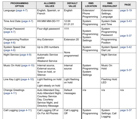
Table 4-1: Keyset Programming – System-Wide Programming . . . 4-5
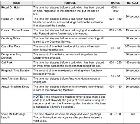
Table 4-2: Keyset Programming – System Timers . . . 4-12
Table 4-3: Keyset Programming – Extension Programming . . . 4-16
Table 4-4: Keyset Programming – Line Programming . . . 4-24
RMS Programming
Page xiv
NUMBER
TITLE
PAGE
RMS Maintenance
Table 6-1: RMS Maintenance System Timers . . . 6-13
Replacement Parts
Page xv
FCC Regulations
Important
1. This equipment complies with Part 68 of FCC rules. On the side of the KSU is a label that contains, among other information, the FCC registration number and ringer equiva-lence number (REN) for this equipment. Customers connecting this equipment to the telephone network shall, before such connection is made, give notice to the telephone company of the particular line(s) to which such connection is to be made, and shall pro-vide the telephone company with the following information:
— Complies with Part 68 of FCC rules
— FCC registration number: HAC LKCGTB-36091-CD-E — USOC numbers of required interface jacks: RJ21X — Facility interface code (FIC): 9.0Y
— Service Order Code (SOC): 02LS2 — Ringer equivalence number (REN): 1.25B — Port Types (as defined in Standard UL60950)
• Extension Ports including Central Bell and Doorphone: TNV3
• PSTN (Central Office) Ports: TNV3
• RS232, Doorstrike and Music on Hold Ports: SELV
NOTE: The REN is used to determine the quantity of devices which may be con-nected to the telephone line. Excessive RENs on the telephone line may result in the devices not ringing in response to an incoming call. To be certain of the number of devices that may be connected to the line, as determined by the total RENs, con-tact the telephone company to determine the maximum REN for the calling area.
The telephone company should also be given notice upon final disconnection of this equipment from the particular line(s).
It is also the responsibility of the customer to provide the telephone company with reg-istration numbers of any other devices which are configured for connection to the tele-phone network.
2. This equipment cannot be used on public coin service provided by the telephone com-pany. Connection to party line service is subject to state tariffs. (Contact the state public utility commission, public service commission, or corporation commission for informa-tion.)
3. If this equipment causes harm to the telephone network, the telephone company will notify the customer in advance that service may be temporarily discontinued. But if advance notice is not practical, the telephone company will notify the customer as soon as possible. Also, the customer will be advised of the right to file a complaint with the FCC, if necessary.
4. The telephone company may make changes in its facilities, equipment, operations, or procedures which may affect the operation of this equipment. If so, the customer shall be given advance notice so that any necessary modifications can be made in order to maintain uninterrupted service.
Page xvi
6. In the event of trouble with the telephone line(s), this equipment must be disconnected from the telephone line(s). If trouble ceases, the equipment must be repaired by an authorized factory service representative. If the trouble continues to occur with the equipment disconnected, the telephone company should be notified that they have a problem. If this is the case, repairs or adjustments made by the telephone company will be made at their expense.
7. Allowing this equipment to be operated in such a manner as to not provide proper answer supervision signaling is in violation of Part 68 of FCC rules. This equipment returns answer supervision signals to the public telephone network when: answered by the called station, answered by the attendant, routed to a recorded announcement that can be administered by the equipment user, and routed to a dial prompt. This equipment also returns answer supervision on all DID calls forwarded back to the public telephone network. Permissible exceptions are: a call is unanswered, busy tone is received, and reorder tone is received.
8. This equipment is capable of providing users access to interstate providers of operator services through the use of equal access codes. Failure to provide equal access capabili-ties is a violation of the Telephone Operator Consumer Services Improvement Act of 1990 and Part 68 of the FCC Rules.
NOTICE
THE TELEPHONE INSTRUMENTS SPECIFICALLY DESIGNED FOR THIS SYSTEM HAVE HEARING-AID COMPATIBLE HANDSETS THAT ARE IN COMPLIANCE WITH SECTION 68.316 OF THE FCC RULES.
CAUTION
Radio Frequency Hazard. This equipment generates and uses radio frequency energy and if not installed and used properly, that is, in strict accordance with the manufacturer's instruc-tions, may cause interference to radio and television reception. It has been type tested and found to comply with the limits for a Class A computing device in accordance with the specifications in Subpart J of Part 15 of FCC Rule. Operation of this equipment in a resi-dential area may cause unacceptable interference to radio and TV reception requiring the operator to take whatever steps are necessary to correct the interference. However, there is no guarantee that interference will not occur in a particular installation. If this equipment does cause interference to radio or television reception, which can be determined by turn-ing the equipment off and on, the user is encouraged to try to correct the interference by one or more of the following measures:
• Reorient the receiving antenna
• Relocate the KSU with respect to the receiver
• Check that the KSU and receiver are not on the same circuit; the KSU must be pow-ered from an isolated, dedicated AC outlet
If necessary, the user should consult the dealer or an experienced radio/television techni-cian for additional suggestions. The user may find the following booklet prepared by the FCC helpful: “How to Identify and Resolve Radio-TV Interference Problems.”
This booklet is available from the U.S. Government Printing Office, Washington, D.C. 20402, Stock No. 004-000-00398-5.
Page xvii
Safety Regulations
Important Safety Instructions
The following safety information is reprinted from UL 1459. When using your telephone equipment, basic safety precautions should always be followed to reduce the risk of fire, elec-tric shock, and injury to persons, including the following:
1. Read and understand all instructions.
2. Follow all warnings and instructions marked on the product.
3. Unplug this product from the wall outlet before cleaning. Do not use liquid cleaners or aerosol cleaners. Use a damp cloth for cleaning.
4. Do not use this product near water (for example, in a wet basement).
5. Do not place this product on an unstable cart, stand, or table. The product may fall, causing serious damage to the product.
6. Slots and openings in the cabinet and the back or bottom are provided for ventilation, to protect it from overheating; these openings must not be blocked or covered. This prod-uct should never be placed near or over a radiator or heat register. This prodprod-uct should not be placed in a built-in installation unless proper ventilation is provided.
7. This product should be operated only from the type of power source indicated in the manual. If you are not sure of the type of power source to your building, consult your dealer or local power company.
8. This product is equipped with a three-wire grounding type plug, a plug having a third (grounding) pin. This plug will only fit into a grounding type power outlet. This is a safety feature. If you are unable to insert the plug into the outlet, contact your electri-cian to replace your obsolete outlet. Do not defeat the safety purpose of the grounding type plug.
9. Do not allow anything to rest on the power cord. Do not locate this product where the cord will be damaged by persons walking on it.
10. Do not use an extension cord with this product’s AC power cord. The AC outlet for this product should not be used for any other electrical equipment.
11. Never push objects of any kind into this product through cabinet slots as they may touch dangerous voltage points or short out parts that could result in a risk of fire or electric shock. Never spill liquid of any kind on the product.
Page xviii
13. Unplug this product from the wall outlet and refer servicing to qualified service person-nel under the following conditions:
a. When the power supply cord or plug is damaged or frayed. b. If liquid has been spilled into the product.
c. If the product has been exposed to rain or water.
d. If the product does not operate normally by following the operating instructions. Adjust only those controls that are covered by the operating instructions because improper adjustment of other controls may result in damage and will often require extensive work by a qualified technician to restore the product to normal operation. e. If the product has been dropped or the cabinet has been damaged.
f. If the product exhibits a distinct change in performance.
14. Avoid using a telephone (other than a cordless type) during an electrical storm. There may be a remote risk of electric shock from lightning.
15. Do not use the telephone to report a gas leak in the vicinity of the leak.
Save These Instructions
CAUTION
Possible Fire and Safety Hazard. To reduce the risk of fire, use only no. 26AWG or larger line cord for CO line connections.
Page xix
Limited Warranty
For a period of 18 months from the date of purchase, INTER-TEL warrants the Equipment (except for fuses and lamps) to be free from defects in material, workmanship, or both, and to comply with specifications for the Equipment, as set forth in the Installation Manual. Buyer's sole and exclusive remedy for breach of this Limited Warranty shall be to have the defective Equipment (or parts) repaired or replaced at INTER-TEL's option. Shipping costs incurred returning warranty work to INTER-TEL shall be paid for by the Buyer. This Limited Warranty extends only to the Buyer, not to any customer, user, or third party. This Limited Warranty does not apply to Equipment (or parts) damaged by improper handling, normal wear and tear, acci-dents, lightning damage, negligence, or improper use or maintenance, and does not apply to Equipment altered without authorization by INTER-TEL. This Limited Warranty does not extend to any claims, suits, damages, liabilities, costs, and expenses arising from any act, action, or inaction of Buyer. Although the Moss-Magnuson Act should not apply, in the event that it is held to apply by a court of competent jurisdiction, the implied warranty of fitness for a particular purpose shall extend for the 18-month period from the date that the Equipment was purchased.
NOTE: THIS WARRANTY IS IN LIEU OF AND EXCLUDES ALL OTHER WARRANTIES, EXPRESS OR IMPLIED, INCLUDING, BUT NOT LIMITED TO, THE IMPLIED WARRANTY OF MERCHANTABILITY OR FITNESS FOR A PARTICULAR PURPOSE. THERE ARE NO WARRANTIES WHICH EXTEND BEYOND THIS LIMITED WARRANTY. IN NO EVENT SHALL INTER-TEL BE LIABLE FOR LOSS OF ANTICIPATED PROFITS, INCIDENTAL OR CONSEQUENTIAL DAMAGES, LOSS OF TIME OR OTHER LOSSES INCURRED BY BUYER IN CONNECTION WITH THE PURPOSE, POSSESSION, OPERATION, OR USE OF THE EQUIPMENT, SUCH CLAIMS BEING EXPRESSLY WAIVED BY THE INSTALLING COMPANY.
NOTICE
Page xx
Software License Agreement
THE FOLLOWING IS A SITE LICENSE AGREEMENT RELATING TO THE INTER-TEL SOFTWARE. PLEASE CAREFULLY READ ALL OF THE TERMS AND CONDITIONS BEFORE PROCEEDING. THE SOFTWARE REFERENCED HEREIN IS LICENSED IN ACCORDANCE WITH THE FOLLOWING TERMS AND CONDITIONS. IF YOU DO NOT ACCEPT SUCH TERMS AND CONDITIONS YOU WILL NOT BE PERMITTED TO USE THE SOFTWARE. IF YOU ACCESS OR USE SUCH SOFTWARE IN CONTRAVEN-TION OF THE TERMS AND PROVISIONS OF THIS AGREEMENT, YOU WILL BE SUB-JECT TO PROSECUTION TO THE FULLEST EXTENT PERMITTED BY LAW.
DEFINITIONS:
“You” means, and “Yours” refers to the original end user purchaser of the Inter-Tel Software Programs. “Computer” means a computer consisting of a single central processing unit, one keyboard and one video display terminal. “Inter-Tel Hardware System” means any proprietary system distributed by Inter-Tel Integrated Systems (hereinafter “Company” or “Inter-Tel”) that operates by means of the Software. “Authorized Dealer” means an individual or entity cur-rently authorized in writing by agreement and in good standing with Inter-Tel entitling the dealer to sell or license the specific Software covered by this license. “Software” means: the computer programs accompanying this License (including, but not limited to, codes, tech-niques, software tools, formats, designs, methods, processes, know-how and ideas) and any and all copies, modifications, upgrades, enhancements and new releases thereof made or acquired by You and any and all manuals and other printed materials accompanying this License or the Software
LICENSE:
(a) Inter-Tel Integrated Systems, Inc. (“Inter-Tel”) grants You a non-exclusive, non-trans-ferable license to install and use the enclosed Inter-Tel Software and accompanying documentation on any one standalone personal computer or Inter-Tel Hardware System (whichever applies). You assume the entire responsibility for the selection and installa-tion of the enclosed Software program(s) in order to achieve desired results. You agree that you are licensing the Program for its end use only and not for resale or redistribu-tion. You must be an Authorized Dealer of the specific Inter-Tel products covered by this license. You will be liable for theft and infringement under applicable patent, copy-right and trademark laws of the United States for unauthorized use of the Software cov-ered by this license.
Inter-Tel reserves all rights in and to all patents, copyrights, trademarks, mask works and any other proprietary rights contained or embodied in the Software.
(b) You may make one (1) copy of the Inter-Tel Software program(s) contained on dis-kette(s) for back-up purposes only, provided that You reproduce and place the Inter-Tel copyright notice on the backup copy. You may make one (1) copy of the Software pro-gram(s) onto one (1) hard drive. You may not copy the Inter-Tel Software propro-gram(s) contained on any media other than diskette; i.e., hard disk drive, ROMs, PALs, Soft-ware Protection Key, etc.
Page xxi (d) You hereby acknowledge and agree that the license granted in this agreement is a site license. I.e., the software may only be installed at the initial end user site licensed for this software and at no other site without the express written consent and relicensing by Inter-Tel Integrated Systems, Inc. You acknowledge and agree that you have the respon-sibility to sublicense the end user of the software with an agreement in writing contain-ing the statement that “the software licensed hereby may only be installed at the initial end user site licensed for this software and at no other site without the express written consent and relicensing by Inter-Tel Integrated Systems, Inc.” It is the specific intent of this site licensing agreement to (1) prohibit the improper copying and/or the multiple use of this software at other than a designated initial licensed site, and to (2) prohibit the right of resale and/or relicensing of the software without the express written consent of Inter-Tel. You agree that your failure to properly sublicense the software to an end user will subject you to responsibility for the losses occasioned to Inter-Tel.
NON-PERMITTED USES:
• You may not use the enclosed program(s) on more than one standalone personal com-puter or Inter-Tel Hardware System at a time and may not load the Software onto any file server or network.
• You may not sublicense, assign or transfer Your rights under the Agreement without the prior written permission of Inter-Tel.
• You may not use, copy, alter or transfer, electronically or otherwise, the Inter-Tel Soft-ware (program(s) or documentation) except as expressly allowed in this Agreement.
• You may not translate, reverse engineer, disassemble or decompile the Inter-Tel Soft-ware.
• You agree that you are licensing the Program for its end use only and not for resale or redistribution.
TERM:
This Agreement is effective from Your date of purchase and shall remain in force until termi-nated. You may terminate the Agreement by returning to Inter-Tel the original diskette(s), ROMs, PALs, or other applicable software media and all copies of the Inter-Tel software pro-gram(s). The Agreement is also terminated if You fail to comply with any term or condition of this Agreement. You agree to return to Inter-Tel the original diskette(s) and other applicable software media and all copies of the Inter-Tel Software program(s) upon such termination. The Company may immediately terminate this license upon notice to you, whereupon you shall immediately destroy all copies of the Program.
WARRANTY:
(a) Inter-Tel warrants to You that the diskette(s), and/or other applicable software media on which the Inter-Tel Software program(s) are furnished are not defective under normal use for a period of ninety (90) days from the date of purchase, as evidenced by a copy of Your sales receipt.
(b) Inter-Tel and its third-party suppliers and vendors' liability and Your exclusive remedy shall be the replacement of any diskette(s) and/or other applicable software media that do not meet the warranty and which are returned to Inter-Tel or an authorized dealer together with a copy of Your paid receipt. THE ABOVE IS THE ONLY WARRANTY OF ANY KIND. ALL OTHER WARRANTIES EITHER EXPRESS OR IMPLIED, INCLUDING, BUT NOT LIMITED TO, THE IMPLIED WARRANTIES OF MER-CHANTABILITY AND FITNESS FOR A PARTICULAR USE ARE HEREBY DIS-CLAIMED. This warranty gives You specific legal rights and You may also have other rights which may vary from state to state.
Page xxii
trade secrets of the Company. You agree to comply with the terms and conditions of this Agreement and agree to treat the Program as the confidential and proprietary infor-mation of the Company.
You shall be solely responsible for the supervision, management and control of your use of the Program and related products and documentation. You hereby indemnify and hold harmless the Company and its affiliates (the Indemnified Parties) against any loss, liability, damages, costs or expenses suffered or incurred by the Indemnified Parties at any time as a result, of any claim, action or proceeding arising out of or relating to your use, operation or implementation of the Program. For purposes of this Agreement, affiliate means any Company division or subsidiary or any other affiliated entity involved in the manufacture or wholesale distribution of Company products.
The Indemnified Parties shall not be responsible, and you shall have no recourse against the Indemnified Parties, for any loss, liability, damages, costs or expenses which may be suffered or incurred at any time by you as a result of your reliance upon or use of the Program, or as a result of any claim, action or proceeding against you arising out of or relating to the use of the Program, or as a result of your defense of any such claim, action or proceeding.
LIMITS OF LIABILITY:
In no event shall Inter-Tel or its third-party suppliers and vendors be liable for any losses (whether in tort, contract or otherwise) incurred in connection with the purchase, sale, posses-sion, operation, or use of the Software (separately or in combination with other products) including, but not limited to loss of time, loss of anticipated profits, loss of data, loss of infor-mation, loss of business, loss of revenue, loss of goodwill or loss of anticipated savings or other business losses, losses relating to routing or programming errors, unauthorized use or access of all intrastate, interstate, and international long distance services, or such access or use by voice mail, DISA, auto attendant, or 800 or 900 services by end-users or unrelated third par-ties, losses related to the use of copyrighted music with Inter-Tel Software, and to the extent such limitation is permitted by applicable law, losses and damages resulting from physical injury to tangible property or death or injury of any person whether arising from Inter-Tel's negligence, breach of contract or otherwise. IN NO EVENT SHALL INTER-TEL OR ITS THIRD-PARTY SUPPLIERS AND VENDORS BE LIABLE FOR ANY INCIDENTAL OR CONSEQUENTIAL DAMAGES, DIRECTLY OR INDIRECTLY ARISING FROM USE OR INABILITY TO USE THE SOFTWARE, SEPARATELY OR IN COMBINATION WITH OTHER PRODUCTS. IN NO EVENT SHALL THE TOTAL LIABILITY OF INTER-TEL DAMAGES EXCEED THE AMOUNT PAID BY YOU FOR THE SOFTWARE.
ENTIRE AGREEMENT:
This Agreement constitutes the entire agreement between You and Inter-Tel and supersedes any and all prior agreements between Inter-Tel and You with regard to the Inter-Tel Software. No amendment, modification or waiver of this Agreement will be valid unless set forth in a written instrument signed by the party to be bound thereby. This Agreement shall be governed by the laws of the State of Arizona. No failure or delay on the part of Inter-Tel to enforce its rights hereunder shall operate as a waiver of any right.
This Agreement and any disputes arising hereunder shall be governed by the laws of the State of Arizona, United States of America, without regard to conflicts of laws principles. The par-ties hereby expressly exclude the application of the U.N. Convention on Contracts for the International Sale of Goods to the Agreement.
GOVERNMENT RESTRICTED RIGHTS:
The Software is provided with restricted rights. Use, duplication or disclosure by the govern-ment is subjected to restrictions set forth in subparagraph c (1) (ii) of the Rights in Technical Data and Computer Software clause at DFARS 252.227-7013 (Oct. 1988) and FAR 52.227-14 and 52.227-19 (June 1987). Contractor is Inter-Tel Integrated Systems, Inc., Chandler, Arizona 85226.
Inter-Tel Integrated Systems, Inc. Chandler, AZ 85226
Page 1-1
EW
Overview
CONTENTS
PAGE
Page 1-2 Introduction
1. INTRODUCTION
1.1 The Encore System is a versatile and easy-to-use telephone system with the following features:
• Can accommodate up to eight loop-start lines and up to 18 extensions
• Has modular construction that allows it to be upgraded by adding various system expansion cards
• Can operate with system Keysets or standard single-line telephones
• Has remote access and maintenance capability
• Encore Keysets have a simple-to-use, menu-driven interface
1.2 Your Encore system consists of the wall-mounted Key Service Unit (KSU), to which line and extension connections are made.
1.3 The Encore System’s modular design allows it to grow as your customer’s business grows. No matter what size system you start with, you can expand up to the maximum capac-ity. The base system includes either two or four loop-start line and up to six extension connec-tions. By adding system expansion cards to these base systems you can have up to eight loop-start lines and up to 18 extensions.
1.4 The system Keyset has a large display area that features an intuitive menu-driven inter-face. Display Keys activate the features that are shown on the keyset’s display. It is not neces-sary to dial any feature codes when using the Keyset. This makes the system easy to use and saves you time.
Page 1-3
About This Manual
EW
2. ABOUT THIS MANUAL
2.1 This Installation, Programming, and Maintenance Manual is your guide to installing, programming, and maintaining the Encore phone system.
• The Installation chapter covers the system equipment. (page2-1)
• The Features chapter includes a description of the system’s features and provides instructions for using a Keyset or standard single-line telephone with the system. (page3-1)
• The Keyset Programming chapter is a system programming reference for using the key-set to perform programming functions. It also includes copies of the System Program Planning Sheets. (page4-1)
• The RMS Programming chapter is a system programming reference for using the RMS software to perform most programming functions, excluding some specific keyset pro-gramming operations. (page5-1)
• The RMS Maintenance chapter describes the Diagnostics, Pro-Active Maintenance, and System Timers portions of the Remote Management Software. (page6-1)
• The Troubleshooting chapter details maintenance procedures. (page7-1)
Page 1-4 System Hardware
3. SYSTEM HARDWARE
3.1 The system Key Service Unit houses a CPU and a power supply unit. The CPU pro-vides six extension interfaces but does not include any line interfaces; at least one Line card is required for line interfaces. The Main Distribution Frame (MDF) area of the CPU contains the connection points for all required extension and line cabling. (See page 2-7 for cabling infor-mation.)
3.2 The CPU also acts as a connection platform for all system expansion cards, as shown below. The system expansion cards are as follows:
• Extension Card: Each Extension Card provides interfaces for six extensions and a con-nector for a Line Card. You can install up to two Extension Cards for a total of 12 extensions, in addition to the six extensions provided by the CPU.
• Line Card: This card provides interfaces for two loop start lines. You can install two Line Cards on the CPU and one on each of the Extension Cards for a total of eight lines.
• Voice Messaging Module: This card provides up to 80 minutes of voice storage. When installed, a system Answering Machine can be enabled and each extension can be vided with a voice message box. The Voice Messaging Module is also required to pro-vide a personalized greeting in the Courtesy and Auto Attendant services.
PSTN card C.O. 1& 2
PSTN card C.O. 3 & 4
Line Card Lines 5 & 6
Line Card Lines 7 & 8
Power
Supply
Extension Card 6 Extension ports
Page 1-5
Keysets
EW
4. KEYSETS
4.1 The system Keyset, shown below, is specially designed for use with the Encore system. It features a four-line display that shows prompts and menus with selectable options. This unique menu-driven interface makes the system simple to use – no codes are needed to pro-gram and activate features. System propro-gramming can also be performed via a Keyset using the intuitive menu-driven interface.
4.2 The Keyset features eight Programmable Keys, which are pre-programmed to access lines, and four Function Keys which group frequently used features in a logical manner. 4.3 The Keyset is fully handsfree, so you can make calls, receive calls, and use its features without lifting the handset.
Handset
Speaker
Programmable Line/Feature Keys
Function Keys: Hold, Program, Message, and Directory
Display
Display Keys
Scroll Key
Microphone
Speaker Key
with light Mute Keywith light
Light for ringing calls and waiting messages
Volume Keys Keypad Edit
Page 1-6 Feature Summary
5. FEATURE SUMMARY
5.1 System, keyset, single-line set, and attendant features are listed below. Those features marked with an asterisk (*) require additional equipment. For complete descriptions and oper-ating instructions, refer to the Installation (page 2-1) and Features (page 3-1) chapters.
A. SYSTEM FEATURES
General System Features
• Flexible incoming ring assignments (alternate point answering)
• Flexible night ringing arrangement (night ring mode)
• Courtesy Service
• Variable system timers
• Internal paging
•∗ Optional Voice Messaging with: — Customized Courtesy Service — Answering Machine Service — Auto-Attendant Service
•∗ Optional Doorbox
•∗ Optional door strike
•∗ Optional external music source for outside call music-on-hold
•∗ Optional external paging equipment
•∗ Optional system battery back-up
•∗ Optional long-line extension
•∗ Optional central bell
System Maintenance and Record Keeping Features
• System Programming via Keyset (defaults to Extension 20)
•∗ Optional Call Logging
•∗ Remote Management Software Outside Call Features
• Dual-tone multi-frequency (DTMF) or dial-pulse signaling
• CO line restriction
• Toll restriction
• Day and night modes of operation
Page 1-7
Extension Features
EW
B. EXTENSION FEATURES
• Hands-free answering of internal calls on Keysets
• On-hook dialing on Keysets
• Direct line key selection on Keysets
• System/station speed dialing
• Last number redial
• System hold
• Conference calls
• Do-not-disturb
• Camp-on and call waiting
• Call transfer
• Call forwarding
•∗ Headset compatible
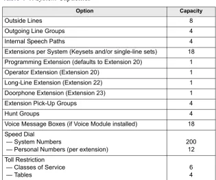
6. SYSTEM CAPACITIES
6.1 This table details the capacities of various system options available. Table 1-1:
System Capacities
Option Capacity
Outside Lines 8
Outgoing Line Groups 4
Internal Speech Paths 4
Extensions per System (Keysets and/or single-line sets) 18 Programming Extension (defaults to Extension 20) 1
Operator Extension (Extension 20) 1
Long-Line Extension (Extension 22) 1
Doorphone Extension (Extension 23) 1
Extension Pick-Up Groups 4
Hunt Groups 4
Voice Message Boxes (if Voice Module installed) 18 Speed Dial
— System Numbers
— Personal Numbers (per extension)
200 12 Toll Restriction
— Classes of Service — Tables
Page 2-1
INS
TALL
A
TI
ON
2
Installation
CONTENTS
PAGE
Page 2-2 Introduction
1. INTRODUCTION
1.1 This section of the manual describes specifications and installation for the following Encore System hardware:
• Cabling and the Main Distribution Frame (MDF)
• Key Service Unit (KSU)
• Keysets and Single-Line Sets
• Optional Equipment
NOTICE
Page 2-3
System Installation Checklist
INS
TALL
A
TI
ON
2
2. SYSTEM INSTALLATION CHECKLIST
2.1 System installation is performed in the following order. Detailed instructions and fig-ures for each step are located throughout this chapter.
!
Read the safety and precaution information on page xvii.!
Plan the installation, including the Key Service Unit (KSU) location, Keyset and single-line set locations, cable runs, and optional equipment. See page 2-4 for details.!
Run cables to the keyset and single-line set locations. See page 2-7 for details.• Run wiring to any optional equipment, such as the external paging equipment, external music source, long-line extension, Doorphone, doorstrike, or central bell.
• Terminate the cables on modular jack assemblies at the Keyset and single-line set locations.
• Perform the loop resistance test for each extension’s cable.
!
Install system expansion cards in the KSU, as necessary, to provide the required func-tionality. See page 2-13 for details. At minimum, you should install the following:• At least one Line Card must be installed to make external calls.
• A Extension Card must be installed if more than six extensions, or more than four lines are required.
• A Voice Messaging Module must be installed to provide Voice Messaging or Answering Machine functionality.
!
Ground the Extension Cards and KSU. See page 2-16 for details.!
Mount the KSU on the wall. See page 2-18 for details.!
Connect the extension and line cabling to the KSU. See page 2-19 for details.!
Install the telephones and any optional Keyset equipment, such as headsets. See pages 24 through 26 for details.!
Turn on the system and ensure that all equipment is working properly. See page 2-32 for details.!
Refer to the Refer to the Getting Started document to perform initial programming for the system. See “RMS Programming” on page 5-1 and “Keyset Programming” on page 4-1 for information on detailed system programming.!
Provide customer training. See page 2-38 for details.CAUTION
Page 2-4 Planning the Installation
3. PLANNING THE INSTALLATION
3.1 To make installation easier, use the following information when preparing to install the system.
A. ESTABLISH SUITABLE ENVIRONMENTAL CONDITIONS FOR THE SYSTEM
Location
3.2 The KSU is intended for installation in a residential or office-type environment. It must be mounted on a dry, flat wall.
3.3 Select the KSU location to minimize cable run length. Keysets and single-line sets con-nected to the system must not exceed a loop limit of 100 ohms (approximately 1500 feet/500 meters) using 24AWG wire. The long-line extension (Extension 22) loop limit is 366 ohms (1.2 miles/2 kilometers). The ohm values are loop measurements; the values in parentheses are the maximum one-way measurements from the KSU.
3.4 Allow sufficient free space all around the KSU for ventilation. Proper placement of the wall-mount bracket, as shown below, will allow sufficient space.
3.5 Allow room near the KSU for the paging amplifier, battery back-up equipment, and the external music source, if used. To avoid interference, the music source should be placed 5 to 10 feet (1.5 to 3 meters) away from the KSU. Make sure there are AC outlets for a music source and a paging amplifier, if they are to be installed. These outlets MUST NOT be on the same circuit as the outlet for the KSU.
Power Supply
3.6 Locate the KSU within 6 feet (2 meters) of an isolated, dedicated, 105–125VAC, 57– 63Hz, 15A, single-phase commercial power source.
NOTE: This must be an isolated, dedicated AC circuit for proper operation. All three wires (power, neutral, and ground) must be run separately from the outlet to the breaker panel without being bonded to any other wire or circuit. DO NOT plug any other equipment into this outlet. To maintain the protection provided by the isolated, dedicated circuit, the length of the AC power cord limits the distance between the power supply and the outlet; DO NOT use an extension cord.
3.7 To reduce the effects of AC voltage surges and spikes that may cause system malfunc-tions, false logic, and/or damage to the electronic components, a surge/spike protector is rec-ommended.
4.8 in. (120mm) clearance 20 in.
(500mm)
60 in. (1500mm)
Page 2-5
Establish Suitable Environmental Conditions for the System
INS
TALL
A
TI
ON
2 Supervised CO Lines
3.8 Only supervised CO lines should be used on the Encore System. While the system has timers that will help to prevent unsupervised trunk use, there is no implied warranty that it is invulnerable to unauthorized intrusions and toll fraud.
3.9 If the central office does not provide supervision it will not disconnect the call when one party hangs up; it is possible for a caller to remain connected to a CO trunk circuit. If this happens, and the caller begins dialing, the call could be placed through the Encore System and would then be billed to the system’s owner. The system cannot check this type of call for toll restriction and may not register the call in the call log. This problem could arise when a call is connected to an extension, when a call is in an unsupervised trunk-to-trunk call, or when a call is forwarded or transferred to the public network.
Environment
3.10 The KSU, Keysets, and single-line sets require the following environmental conditions:
NOTE: It is recommended that the maximum operating temperature (as listed above) never be exceeded. Therefore, when installing the KSU and telephones, allow a sufficient margin for error in case of air conditioning failure, routine mechanical maintenance, plant shutdown, etc. As a general guideline, if the conditions are suitable for office personnel, they are also suitable for all equipment operation. A properly controlled environment will help to extend the operating life of the equipment.
3.11 Do not expose the KSU location to direct sunlight, high humidity, heat, dust, or strong magnetic fields (such as those generated by heavy motors and large copy machines).
3.12 Ample air space should be provided for the KSU since the power supply is convection cooled. DO NOT block the cooling vents located on the top and bottom of the KSU. Never place anything on top of the KSU.
Table 2-1:
Encore System Environmental Condition Requirements
REQUIREMENTS IN OPERATION IN STORAGE
KSU Temperature 32° to 104° F (0° C to +40° C)
40° to 185° F (-40° C to +85° C) Telephone Temperature 32° to 113° F
(0° C to +45° C)
40° to 185° F (-40° C to +85° C)
Page 2-6 Assemble the Necessary Tools and Supplies
B. ASSEMBLE THE NECESSARY TOOLS AND SUPPLIES
3.13 You will need the following supplies and tools:
• Industry-standard, two-pair (four-conductor), twisted-pair cable to run from the KSU to Keysets, single-line sets, and CO lines
• One or two 66M1-50-type block connectors
• Four-conductor modular jack assemblies for Keysets and single-line sets
• A high-impedance digital multimeter to check the correct wiring of the modular jack assemblies. Multimeter accuracy must be ±0.5% or better.
• A surge/spike protector to protect the system from AC voltage surges.
• 18AWG wire for grounding
• Punch-down tools (provided) for the IDC Krone connectors
• Standard telephone hand tools and the mounting hardware for the KSU, modular jack assemblies, etc.
• Gas discharge tubes with silicon avalanche suppressors for lightning protection on the CO lines
• Assemble the optional equipment: — Headsets
— External music source
Page 2-7
Extension and CO Line Cabling
INS
TALL
A
TI
ON
2
4. EXTENSION AND CO LINE CABLING
4.1 Prepare a floor plan for the Keyset and single-line set locations, using a star (home run) configuration. Include each telephone’s extension number. Extension number 20 is assigned to the system operator.
A. RUNNING CABLE
4.2 A 25-pair cable is run from the CO lines and extensions and terminated on a 66M1-50-type connecting block that is wall-mounted near the KSU. Then connections are made between the block and the MDF section of the KSU using 25-pair cable (see page 2-19). Finally, bridg-ing clips are installed to complete the connections on the block. This installation method pro-vides easy access to test points for troubleshooting and minimizes the need to change punched-down connections when moving equipment.
• CO line cabling runs from the RJ21X block to the 66M1-50-type connecting block. NOTE: Gas discharge tubes with silicon avalanche suppressors should be installed on all CO lines for lightning protection. Also, in areas with frequent occurrences of light-ning, it is recommended that the cable between the telephone company termination and the gas discharge tubes be at least 75 feet long (the cable may be coiled up if desired).
• All extension cables are terminated on the 66M1-50-type connecting block. The other end of each extension cable is terminated on a four-conductor modular jack assembly at the extension location. From the KSU location, run industry standard, two-pair (four-conductor) or 25-pair, twisted-pair cable to keysets and single-lines sets following these guidelines:
— Install proper type cable for the application according to the National Electrical Code and local building codes. If using multi-pair (e.g., 25-pair) cable runs to mul-tiple extension locations do not include CO lines in a cable being used for exten-sions. Extension circuits should be included in separate multi-pair cable runs. — Avoid cable runs parallel to fluorescent light fixtures or AC lines not in conduit. If
these obstacles are unavoidable, run the cables across them at right angles.
— Do not run extension cables inside electrical conduit already occupied by AC power cable. (To do so is a violation of the National Electrical Code.)
— Do not run cables near equipment with electric motors or through strong magnetic fields, such as those generated by large copy machines, arc welding equipment, etc. — Do not run cables outdoors. The Encore System is designed for indoor wiring only. — Do not place extension cables where they can be stepped on or where they can be
rolled over by office furniture.
— Extension cables must not exceed a loop limit of 100 ohms (approximately 1500 feet/500 meters) using 24AWG wire. The long-line extension (Extension 22) loop limit is 366 ohms (1.2 miles/2 kilometers). The ohm values are loop measurements; the values in parentheses are the maximum one-way measurements from the KSU. NOTE: It is recommended that four-conductor modular jacks be used for all Keyset and single-line set connections. This allows both types of telephones to be easily inter-changed, if necessary. However, if desired, single-line sets can be installed using one-pair cable and four-conductor modular jacks.
CAUTION
Page 2-8 Sample System Layout
B. SAMPLE SYSTEM LAYOUT
4.3 The diagram below shows a suggested layout for the KSU and block(s). You will need two blocks if Expansion cards are installed.
Figure 2-1.
Sample Layout and Cable Assignments
Encore
CONNECTING BLOCKS
Cable B to Expansion Cards
Cable A to CPU To Extensions 26-37
on Expansion Card
To Extensions 20-25 and devices on CPU
To Telco
(enters through side)
(enters through bottom) (Use bridging clips to
Page 2-9
Terminating the Cables at Extension Locations
INS
TALL
A
TI
ON
2
C. TERMINATING THE CABLES AT EXTENSION LOCATIONS
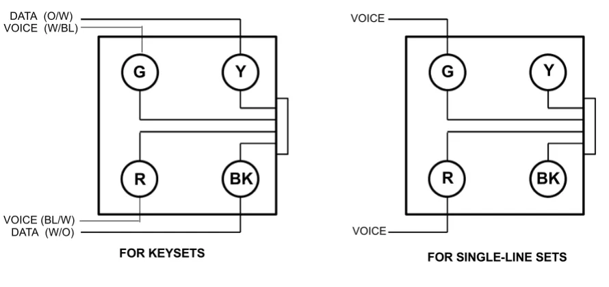
4.4 Terminate the keyset and single-line set cables on four-conductor modular jack assem-blies at the extension location, as shown in the diagram below. Refer to the figure below for a wiring diagram.
NOTE: It is recommended that four-conductor modular jacks be used for all Keyset and single-line set connections. This allows both types of telephones to be easily interchanged, if neces-sary. However, if desired, single-line sets can be installed using one-pair cable and four-conduc-tor modular jacks.
Figure 2-2.
Modular Jack Assembly Wiring
NOTE: Single-line sets use only the Voice pair, not the Data pair.
4.5 Do not mount the assemblies on the wall at this time; they will be wall mounted later when the telephones are installed.
D. PERFORMING LOOP RESISTANCE TESTS
NOTE: If performing the loop resistance test after the system is installed, unplug the keyset from the jack assembly. Then disconnect the bridging clips from the 66M1-50-type connecting block.
4.6 Perform the following loop resistance test for each individual cable: 1. Ensure that the telephone is not connected to the modular jack assembly. 2. Place a short across the RED and GREEN wires on the modular jack assembly.
3. At the connecting block, measure the resistance across the Voice pair wires. The read-ing should not exceed 100 ohms (approximately 1500 feet/500 meters) usread-ing 24AWG wire. The long-line extension (Extension 22) loop limit is 366 ohms (1.2 miles/2 kilo-meters). The ohm values are loop measurements; the values in parentheses are the max-imum one-way measurements from the KSU.
NOTE: Excessive and/or improperly made connections increase the resistance of a cable, which reduces the allowable cable run length.
4. Remove the short after the test is complete. DATA (O/W)
DATA (W/O)
VOICE
VOICE
G
Y
R
BK
G
Y
R
BK
FOR SINGLE-LINE SETS VOICE (W/BL)
VOICE (BL/W)
Page 2-10 Wiring for Operation During Power Failure Conditions
E. WIRING FOR OPERATION DURING POWER FAILURE CONDITIONS
4.7 When planning the extension wiring for the system, consideration should be given to the use of Keysets and single-line telephones in power-fail situations. As Keysets cannot oper-ate without power, Extensions 24, 25, 31 and 37 should either have access to or be equipped with single-line sets if they are to be used in power failure situations.
4.8 Each board with CO line capability is equipped with a power-failure circuit path. In the event of a total system power failure, at least 50% of the equipped lines are switched to exten-sions. Lines 1 and 2 are connected to extensions 24 and 25, the last two extensions on the CPU. Line 5 is connected to extension 31, and line 7 to extension 37, the last extensions on each of the Extension Cards. These line positions are summarized in the table below.
NOTE: If lines are connected to extension positions equipped with Keysets, the user must replace the Keyset with a single-line telephone to answer or make calls during a power failure. Keysets cannot be used during a power failure situation.
F.
SIGNALS AND TONES
Ring Signals
4.9 The system ringing signals are as follows:
Call Processing Signals
4.10 The following signals and tones are heard through the handset or keyset speaker.
CO LINE POWER FAILURE EXTENSION
Line 1 Extension 24
Line 2 Extension 25
Line 5 Extension 31
Line 7 Extension 37
TYPE OF CALL RING SIGNAL
Outside Call 2s on, 4s off
Internal Call 800 ms on, 400 ms off, 800 ms on, 4.0 seconds off Doorphone Call 800 ms on, 5200 ms off
Recalling Call 800 ms on, 400 ms off, 800 ms on, 1000 ms off, 2000 ms on, 1000 ms off
TYPE OF CALL RING SIGNAL
Dial Tone Continuous dual tone of 425 Hz ±5% and 350 Hz ±5% Special Dial Tone
(Single-Line Sets only)
900 ms on, 100 ms off of dial tone
Ringback 800 ms on, 400 ms off, 800 ms on, 4s off
Busy 500 ms on, 500 ms off
Congestion 200 ms on, 200 ms off
Hold 200 ms on, 200 ms off, 200 ms on, 3.4s off
Conference One burst of 200 ms
Page 2-11
Key Service Unit (KSU)
INS TALL A TI ON 2
5. KEY SERVICE UNIT (KSU)
A. KSU DESCRIPTION
5.1 The KSU is a compact, wall-mounted unit that houses the system power supply, the CPU, and the expansion cards. The KSU performs all control and switching activities for the system, including: detecting incoming CO calls, storing speed-dial numbers, processing data-controlled features, and controlling the interaction between keysets, single-line sets, CO lines, and voice channels.
5.2 The KSU dimensions and weight are:
5.3 The CPU has 2MB of random-access memory (RAM) and 4MB of read-only memory (ROM). The software code for the system is stored in the non-volatile ROM memory, and the programmed database and speed-dial numbers are stored in the RAM memory.
5.4 The RAM memory is protected by a capacitor. The capacitor will protect the pro-grammed database until the accumulated system downtime exceeds 2-3 months (depending on the size of the database).
5.5 The connectors on the CPU are shown below. Components that are not labeled are not currently used.
Height 18 in. (450 mm) Width 12 in. (304.5 mm) Depth 3 in. (71.6 mm) Weight 5.5 lb. (2.5 kg)
GROUNDING CONNECTOR
DOORSTRIKE RELAY LINES 1 & 2
LINES 3 & 4
Page 2-12 Unpack and Inspect The KSU
B. UNPACK AND INSPECT THE KSU
5.6 Before beginning the installation:
1. Unpack the KSU and lay it on a flat surface with the cover facing up.
2. Remove the MDF cover by removing the retaining screw at the bottom and sliding the MDF cover upward. Open the KSU by loosening the two retaining screws on the left side of the cover and lifting the cover off the hooks located on the right side. (The screws on the KSU will not come completely out of the plastic.)
3. Inspect the KSU. If the KSU or any of its internal components are damaged, contact your supplier immediately.
4. Ensure that the correct Language Card is installed in the KSU. This card determines the language that will be used by the Courtesy Service prompts (it does not affect Voice Messaging). There are separate cards for English, Spanish, and French. See the Parts chapter for part numbers. If the wrong Language Card is installed, replace it with the correct card.
5. If you are installing one or more Expansion cards, proceed to the next section. Other-wise, replace the KSU cover; then proceed to page 2-18.
Retaining screw for MDF cover
Remove the MDF cover by sliding upwards
Inter-Tel Encore Inter-Tel Encore Two retaining screws
Lift off cover toward right
SYSTEM MUST BE DISCONNECTED FROM MAINS SUPPLY BEFORE
REMOVING LID
Page 2-13
Install the Expansion Cards in the KSU
INS
TALL
A
TI
ON
2
C. INSTALL THE EXPANSION CARDS IN THE KSU
5.7 The KSU has circuitry for six extensions. Expansion cards add circuitry for additional extensions and CO lines. Up to two Extension Cards and four Line Cards can be installed as shown below.
5.8 An optional Voice Messaging Module can also be installed. This card provides up to 80 minutes of voice storage for extension voice message boxes and the Answering Machine fea-ture. It is also used for the Automated Attendant and Custom Courtesy Service features. Voice Messaging Module
5.9 When the Voice Messaging Module is installed, a system Answering Machine can be enabled and each extension can be provided with a voice box. A minimum of two minutes stor-age is allocated automatically to each programmed extension. The remaining capacity is dynamically allocated.
5.10 The Voice Messaging Module is also required to provide a personalized greeting in either the Courtesy or Auto Attendant services.
5.11 The Voice Messaging Module is located on the CPU as shown below. To install, insert the module into the connector on the CPU.
CAUTION
Electrostatic Discharge Hazard. The cards contain static-sensitive components. Lift them only by the edges and carefully handle the components. Always use electrostatic protection when inserting and removing circuit boards. Never insert or remove circuit boards when power is applied to the system.
Page 2-14 Install the Expansion Cards in the KSU
Line Card
5.12 The Line card adds two CO lines to the system. Because the CPU does not have CO line connectors, at least one Line Card must be installed for CO line access. Line Cards can be installed on the CPU or on Extension Cards, as shown below.
NOTE: If only one line on a two-port Line Card will be used, the second line must be disabled using system programming.
5.13 To install, insert the Line Card into one of the connectors on the CPU or a connector on a Extension Card.
Locate Line Card Here
Locate Line Card Here Locate Line Card
Here
Locate Line Card Here
TOP
Insert thisPage 2-15
Install the Expansion Cards in the KSU
INS
TALL
A
TI
ON
2 Extension Card
5.14 Each Extension Card has circuitry for an additional six extensions. Up to two Extension Cards can be installed.
5.15 The Extension Card has a grounding connector, Line Card and line connectors, and six extension connectors. The figure below shows the Extension Card connectors. The six exten-sions are numbered 26 through 31 for the card in the lower connector on the CPU and 32 through 37 for the card in the upper connector.
Position 2
Position 1
Line Card Connectors Grounding Connector
Line Connector
Page 2-16 Grounding the KSU
5.16 To install, insert the Extension Card into the connectors on the CPU. The card must be inserted with the column support located under the line termination points as shown below.
NOTE: To protect the system against high voltage surges on incoming CO lines (for example, caused by lightning), the ground connector on the Extension Cards must be connected to the grounding point on the CPU. Then the CPU must be attached to earth ground. It should also be equipped with a surge/spike protector (see next page).
D. GROUNDING THE KSU
5.17 To protect the system against high voltage surges on incoming CO lines (for example, caused by lightning), the ground connector on the Extension Cards must be connected to the grounding point on the CPU. Then the CPU must be attached to earth ground. It should also be equipped with a surge/spike protector.
5.18 To ground the cards and CPU, run wire to the grounding terminals as shown below. Then connect the grounding terminal on the CPU to an earth ground.
PSTN Expansion Card
Page 2-17
Replace the KSU Cover
INS
TALL
A
TI
ON
2
E. REPLACE THE KSU COVER
5.19 If expansion cards have been installed in the KSU, you must remove the break-off pan-els from the side of the KSU cover to allow access to the connectors.
5.20 Position the cover over the hooks on the right edge of the KSU and then lower the cover onto the KSU. Tighten the retaining screws on the cover.
Encore
Break-Off Panels
Page 2-18 Wall-Mount the KSU
F.
WALL-MOUNT THE KSU
5.21 When a suitable location has been found, mark the screw locations on the mounting sur-face, using the mounting bracket provided. Position the bracket on the wall and ensure that it is level. Mark the screw holes, then drill four holes in the wall at the marked locations. If the KSU is being mounted on masonry or plasterboard, use suitable fasteners.
5.22 The figure below shows the mounting bracket and the necessary top and side clear-ances.
5.23 Hang the KSU on the bracket, as shown in the figure below. 4.8 in. (120mm)
clearance 20 in.
(500mm)
60 in. (1500mm)
20 in. (500mm) clearance
Locate the mounting bracket in a suitable position and place the KSU onto it by lowering it into position
Page 2-19
Connecting Cables to the KSU
INS
TALL
A
TI
ON
2
G. CONNECTING CABLES TO THE KSU
Wiring Technique
5.24 The extension and line cables connected to the CPU enter the KSU at the bottom of the KSU, as shown below. Remove the break-out panel at the bottom of the KSU and pass the cables that will be connected to the CPU through the cable entry hole.
5.25 Cables that will be attached to the Extension Cards are routed from the left side of the KSU, directly to the cards. (The breakout panels on the side are removed to allow access to the Extension Cards.)
5.26 Pass cable-retaining straps through the hooks provided and pass the cables through the cable-retaining straps until they are adjacent to the appropriate connectors. The cables should be neatly guided into the channel space between the connectors and the KSU case side, ensur-ing that there is sufficient clearance between the cables and the KSU case lid. The cables should remain sheathed inside the KSU housing to within reach of the appropriate connector.
5.27 The tables on the following pages show the connection points between the CPU con-nectors in the KSU and the 66M1-50-type connecting block, using the standard 25 pair cable color code.
Connectors
5.28 The KSU and Extension Cards are equipped with 4-wire IDC Krone connectors. The same connector type is used to terminate the CO lines as is used to terminate the extensions. To punch down the extension and line cables on the IDC Krone connectors, use the special punch-down tool, provided with the KSU.
CAUTION
Safety Hazard. Remove only the knock-out panel(s) required for cable access to the KSU MDF area. Removing the other panels exposes the KSU circuitry unnecessarily and could create a safety hazard.
Install cables along the left side of the KSU, (area in gray), and connect to the appropriate
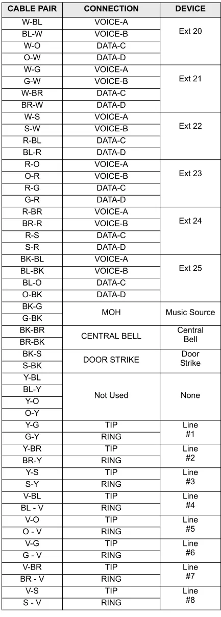
Page 2-20 Main CPU Connections — Cable A
FIGURE 3.
Main CPU Connections — Cable A
Table 2-2:
Main CPU Connections - Cable A
CABLE PAIR CONNECTION DEVICE
W-BL VOICE-A Ext 20 BL-W VOICE-B W-O DATA-C O-W DATA-D W-G VOICE-A Ext 21 G-W VOICE-B W-BR DATA-C BR-W DATA-D W-S VOICE-A Ext 22 S-W VOICE-B R-BL DATA-C BL-R DATA-D R-O VOICE-A Ext 23 O-R VOICE-B R-G DATA-C G-R DATA-D R-BR VOICE-A Ext 24 BR-R VOICE-B R-S DATA-C S-R DATA-D BK-BL VOICE-A Ext 25 BL-BK VOICE-B BL-O DATA-C O-BK DATA-D BK-G
MOH Music Source
G-BK BK-BR
CENTRAL BELL CentralBell BR-BK
BK-S
DOOR STRIKE StrikeDoor S-BK
Y-BL
Not Used None
BL-Y Y-O O-Y
Y-G TIP Line
#1
G-Y RING
Y-BR TIP Line
#2
BR-Y RING
Y-S TIP Line
#3
S-Y RING
V-BL TIP Line
#4
BL - V RING
V-O TIP Line
#5
O - V RING
V-G TIP Line
#6
G - V RING
V-BR TIP Line
#7
BR - V RING
V-S TIP Line
#8
Page 2-21
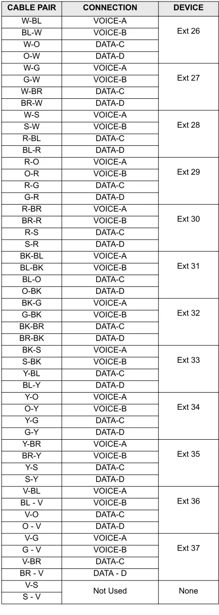
Expansion Card Connections — Cable B
INS TALL A TI ON 2
FIGURE 4.
Expansion Card Connections — Cable B
Table 2-3:
Expansion Card Connections - Cable B
CABLE PAIR CONNECTION DEVICE
W-BL VOICE-A Ext 26 BL-W VOICE-B W-O DATA-C O-W DATA-D W-G VOICE-A Ext 27 G-W VOICE-B W-BR DATA-C BR-W DATA-D W-S VOICE-A Ext 28 S-W VOICE-B R-BL DATA-C BL-R DATA-D R-O VOICE-A Ext 29 O-R VOICE-B R-G DATA-C G-R DATA-D R-BR VOICE-A Ext 30 BR-R VOICE-B R-S DATA-C S-R DATA-D BK-BL VOICE-A Ext 31 BL-BK VOICE-B BL-O DATA-C O-BK DATA-D BK-G VOICE-A Ext 32 G-BK VOICE-B BK-BR DATA-C BR-BK DATA-D BK-S VOICE-A Ext 33 S-BK VOICE-B Y-BL DATA-C BL-Y DATA-D Y-O VOICE-A Ext 34 O-Y VOICE-B Y-G DATA-C G-Y DATA-D Y-BR VOICE-A Ext 35 BR-Y VOICE-B Y-S DATA-C S-Y DATA-D V-BL VOICE-A Ext 36
BL - V VOICE-B
V-O DATA-C
O - V DATA-D
V-G VOICE-A
Ext 37
G - V VOICE-B
V-BR DATA-C
BR - V DATA - D
V-S
Not Used None
Page 2-22 Expansion Card Connections — Cable B
CO Line Connections
5.29 The first A and B pair on each Line Card is used to terminate one line and the second C and D pair is used to terminate a second line. Refer to the chart on page 2-20 for wiring con-nections.
5.30 CO lines 1 to 4 are terminated in the CPU connectors, as shown below. The cables for these connections are routed into the KSU through the breakout panel at the bottom.
5.31 CO lines 5 to 8 are terminated on the two Extension Cards, as shown below. The first Extension Card provides a connector for lines 5 and 6 and the second Extension Card provides a connector for lines 7 and 8. The cables for these connections are routed into the KSU from the left, through the breakout panels on the KSU cover.
Line Card
Line Card
A
B
C
D
A
B
C
D
Line 1
Line 2
Line 3
Line 4
PSTN Expansion Card
PSTN Expansion Card
A B C D Line Card
Line Card
A B C D
Extension Cards
Line 5 Line 6