726+,%$
Telecommunication Systems DivisionCTX100 and CTX670
General Description
Publication Information
Toshiba America Information Systems, Inc., Telecommunication Systems Division, reserves the right, without prior notice, to revise this information publication for any reason, including, but not limited to, utilization of new advances in the state of technical arts or to simply change the design of this document.
Further, Toshiba America Information Systems, Inc., Telecommunication Systems Division, also reserves the right, without prior notice, to make such changes in equipment design or components as engineering or manufacturing methods may warrant.
© Copyright 2002
Toshiba America Information Systems, Inc. Telecommunication Systems Division
All rights reserved. No part of this manual, covered by the copyrights hereon, may be reproduced in any form or by any means—graphic, electronic, or mechanical, including recording, taping, photocopying, or information retrieval systems—without express written permission of the publisher of this material.
Strata and SmartMedia are registered trademarks of Toshiba Corporation. Stratagy is a registered trademark of Toshiba America Information Systems, Inc. Trademarks, registered trademarks, and service marks are the property of their respective owners.
Strata CTX100 and CTX670
General End User Information
The Strata CTX100 or CTX670 Digital Business Telephone System is registered in accordance with the provisions of Part 68 of the Federal Communications Commission’s Rules and Regulations.
FCC Requirements
Means of Connection: The Federal Communications Commission (FCC) has established rules which permit the Strata CTX100 or CTX670 system to be connected directly to the telephone network. Connection points are provided by the telephone company—connections for this type of customer-provided equipment will not be provided on coin lines. Connections to party lines are subject to state tariffs. Incidence of Harm: If the system is malfunctioning, it may also be disrupting the telephone network. The system should be disconnected until the problem can be determined and repaired. If this is not done, the telephone company may temporarily disconnect service. If possible, they will notify you in advance, but, if advance notice is not practical, you will be notified as soon as possible. You will be informed of your right to file a complaint with the FCC.
Service or Repair: For service or repair, contact your local Toshiba telecommunications distributor. To obtain the nearest Toshiba telecommunications distributor in your area, log onto www.toshiba.com/taistsd/locator.htm or call (800) 222-5805 and ask for a Toshiba Telecom Dealer.
Telephone Network Compatibility: The telephone company may make changes in its facilities, equipment, operations, and procedures. If such changes affect the compatibility or use of the Strata CTX100 or CTX670 system, the telephone company will notify you in advance to give you an opportunity to maintain uninterrupted service.
Notification of Telephone Company: Before connecting a Strata CTX100 or CTX670 system to the telephone network, the telephone company may request the following: 1. Your telephone number.
2. FCC registration number:
• Strata CTX100 or CTX670 may be configured as a Key, Hybrid or PBX telephone system. The appropriate configuration for your system is dependent upon your operation of the system.
• If the operation of your system is only manual selection of outgoing lines, it may be registered as a Key telephone system.
• If your operation requires automatic selection of outgoing lines, such as dial access, Least Cost Routing, Pooled Line Buttons, etc., the system must be registered as a Hybrid telephone system. In addition to the above, certain features (tie Lines, Off-premises Stations, etc.) may also require Hybrid telephone system registration in some areas.
• If you are unsure of your type of operation and/or the appropriate FCC registration number, contact your local Toshiba telecommunications distributor for assistance.
CTX100 Registration Numbers
PBX: CJ6MUL-35931-PF-E, fully-protected PBXs
Hybrid: CJ6MUL-35930-MF-E, fully-protected multifunction systems Key: CJ6MUL-35929-KF-E, fully-protected telephone key systems • CTX670 Registration Numbers
PBX: CJ6MUL-35934-PF-E, fully-protected PBXs
Hybrid: CJ6MUL-35933-MF-E, fully-protected multifunction systems Key: CJ6MUL-35932-KF-E, fully-protected telephone key systems • Ringer equivalence number: 0.3B. The ringer equivalence number (REN) is
useful to determine the quantity of devices which you may connect to your telephone line and still have all of those devices ring when your number is called. In most areas, but not all, the sum of the RENs of all devices connected to one line should not exceed five (5.0B). To be certain of the number of devices you may connect to your line, as determined by the REN, you should contact your local telephone company to ascertain the maximum REN for your calling area.
RJ21/2E/2F/2G/2HX/RJ49C (see Network Requirements in this document). Items 2, 3 and 4 are also indicated on the equipment label.
4. Authorized Network Parts: 02LS2/GS2, 02RV2-T/O, OL13C/B, T11/12/31/32M, 04DU9-BN/DN/1SN, 02IS5, 04DU9-BN/DN/1SN1ZN
Radio Frequency Interference
Warning: This equipment generates, uses, and can radiate radio frequency energy and if not installed and used in accordance with the manufacturer’s instruction manual, may cause interference to radio communications. It has been tested and found to comply with the limits for a Class A computing device pursuant to Subpart J of Part 15 of FCC Rules, which are designed to provide reasonable protection against such interference when operated in a commercial environment. Operation of this equipment in a residential area is likely to cause interference, in which case, the user, at his/her own expense, will be required to take whatever measures may be required to correct the interference.
This system is listed with Underwriters Laboratory.
UL Requirement: If wiring from any telephone exits the building or is subject to lightning or other electrical surges, then secondary protection is required. Secondary protection is also required on DID, OPS, and Tie lines. (Additional information is provided in this manual.)
Important Notice — Music-On-Hold In accordance with U.S. Copyright Law, a license may be required from the American Society of Composers, Authors and Publishers, or other similar organization, if radio or TV broadcasts are transmitted through the music-on-hold feature of this telecommunication system. Toshiba America Information Systems, Inc., hereby disclaims any liability arising out of the failure to obtain such a license. CP01, Issue 8, Part I Section 14.1
Notice: The Industry Canada label identifies certified equipment. This certification means that the equipment meets certain telecommunications network protective, operational and safety requirements as prescribed in the appropriate Terminal Equipment Technical Requirements document(s). The Department does not guarantee the Equipment will operate to the user’s satisfaction.
Before installing this equipment, users should ensure that it is permissible to be connected to the facilities of the local telecommunications company. The equipment must also be installed using an acceptable method of connection. The customer should be aware that compliance with the above conditions may not prevent degradation of service in some situations.
Repairs to certified equipment should be coordinated by a representative designated by the supplier. Any repairs or alterations made by the user to this equipment, or equipment malfunctions, may give the telecommunications company cause to request the user to disconnect the equipment.
Users should ensure for their own protection that the electrical ground connections of the power utility, telephone lines and internal metallic water pipe system, if present, are connected together. This precaution may be particularly important in rural areas.
CAUTION! Users should not attempt to make such connections themselves, but should contact the appropriate electric inspection authority, or electrician, as appropriate.
CP01, Issue 8, Part I Section 14.2
Notice: The Ringer Equivalence Number (REN) assigned to each terminal device provides an indication of the maximum number of terminals allowed to be connected to a telephone interface. The terminal on an interface may consist of any combination of devices subject only to the requirement that the sum of the Ringer Equivalence Numbers of all the Devices does not exceed 5.
TOSHIBA AMERICA INFORMATION SYSTEMS, INC. (
“
TAIS
”
)
Telecommunication Systems Division License AgreementIMPORTANT: THIS LICENSE AGREEMENT (“AGREEMENT”) IS A LEGAL AGREEMENT BETWEEN YOU (“YOU”) AND TAIS. CAREFULLY READ THIS LICENSE AGREEMENT. USE OF ANY SOFTWARE OR ANY RELATED INFORMATION (COLLECTIVELY, “SOFTWARE”) INSTALLED ON OR SHIPPED WITH A TAIS TELECOMMUNICATION SYSTEM PRODUCT OR OTHERWISE MADE AVAILABLE TO YOU BY TAIS IN WHATEVER FORM OR MEDIA, WILL CONSTITUTE YOUR ACCEPTANCE OF THESE TERMS, UNLESS SEPARATE TERMS ARE PROVIDED BY THE SOFTWARE SUPPLIER. IF YOU DO NOT AGREE WITH THE TERMS OF THIS LICENSE AGREEMENT, DO NOT INSTALL, COPY OR USE THE SOFTWARE AND PROMPTLY RETURN IT TO THE LOCATION FROM WHICH YOU OBTAINED IT IN ACCORDANCE WITH APPLICABLE RETURN POLICIES. EXCEPT AS OTHERWISE AUTHORIZED IN WRITING BY TAIS, THIS SOFTWARE IS LICENSED FOR DISTRIBUTION ONLY TO END-USERS PURSUANT TO THIS LICENSE AGREEMENT.
1. License Grant. The Software is not sold; it is licensed upon payment of applicable charges. TAIS grants to you a personal, non-transferable and non-exclusive right to use the copy of the Software provided under this License Agreement. You agree you will not copy the Software except as necessary to use it on one TAIS system at a time at one location. Modifying, translating, renting, copying, distributing, transferring or assigning all or part of the Software, or any rights granted hereunder, to any other persons and removing any proprietary notices, labels or marks from the Software is strictly prohibited; You agree violation of such restrictions will cause irreparable harm to TAIS and provide grounds for injunctive relief, without notice, against You or any other person in possession of the Software. You and any other person whose possession of the software violates this License Agreement shall promptly surrender possession of the Software to TAIS, upon demand. Furthermore, you hereby agree not to create derivative works based on the Software. TAIS reserves the right to terminate this license and to immediately repossess the software in the event that You or any other person violates this License Agreement.
2. Intellectual Property. You acknowledge that no title to the intellectual property in the Software is transferred to you. You further acknowledge that title and full ownership rights to the Software will remain the exclusive property of TAIS and/or its suppliers, and you will not acquire any rights to the Software, except the license expressly set forth above. You will not remove or change any proprietary notices contained in or on the Software. The Software is protected under US patent, copyright, trade secret, and/or other proprietary laws, as well as international treaties. Any transfer, use, or copying of the software in violation of the License Agreement constitutes copyright infringement. You are hereby on notice that any transfer, use, or copying of the Software in violation of this License Agreement constitutes a willful infringement of copyright.
3. No Reverse Engineering. You agree that you will not attempt, and if you employ employees or engage contractors, you will use your best efforts to prevent your employees and contractors from attempting to reverse compile, reverse engineer, modify, translate or disassemble the Software in whole or in part. Any failure to comply with the above or any other terms and conditions contained herein will result in the automatic termination of this license and the reversion of the rights granted hereunder back to TAIS.
4. Limited Warranty. THE SOFTWARE IS PROVIDED “AS IS” WITHOUT WARRANTY OF ANY KIND. TO THE MAXIMUM EXTENT PERMITTED BY APPLICABLE LAW, TAIS AND ITS SUPPLIERS DISCLAIM ALL WARRANTIES WITH REGARD TO THE SOFTWARE, EITHER EXPRESS OR IMPLIED, INCLUDING, BUT NOT LIMITED TO, THE WARRANTY OF NON-INFRINGEMENT OF THIRD PARTY RIGHTS, THE WARRANTY OF YEAR 2000 COMPLIANCE, AND THE IMPLIED WARRANTIES OF MERCHANTABILITY AND FITNESS FOR A PARTICULAR PURPOSE. THE ENTIRE RISK AS TO THE QUALITY AND PERFORMANCE OF THE SOFTWARE IS WITH YOU. NEITHER TAIS NOR ITS SUPPLIERS WARRANT THAT THE FUNCTIONS CONTAINED IN THE SOFTWARE WILL MEET YOUR REQUIREMENTS OR THAT THE OPERATION OF THE SOFTWARE WILL BE UNINTERRUPTED OR ERROR-FREE. HOWEVER, TAIS WARRANTS THAT ANY MEDIA ON WHICH THE SOFTWARE IS FURNISHED IS FREE FROM DEFECTS IN MATERIAL AND WORKMANSHIP UNDER NORMAL USE FOR A PERIOD OF NINETY (90) DAYS FROM THE DATE OF DELIVERY TO YOU.
5. Limitation Of Liability. TAIS’ ENTIRE LIABILITY AND YOUR SOLE AND EXCLUSIVE REMEDY UNDER THIS LICENSE AGREEMENT SHALL BE AT TAIS’ OPTION REPLACEMENT OF THE MEDIA OR REFUND OF THE PRICE PAID. TO THE MAXIMUM EXTENT PERMITTED BY APPLICABLE LAW, IN NO EVENT SHALL TAIS OR ITS SUPPLIERS BE LIABLE TO YOU FOR ANY CONSEQUENTIAL, SPECIAL, INCIDENTAL OR INDIRECT DAMAGES FOR PERSONAL INJURY, LOSS OF BUSINESS PROFITS, BUSINESS INTERRUPTION, LOSS OF BUSINESS INFORMATION/DATA, OR ANY OTHER PECUNIARY LOSS OF ANY KIND ARISING OUT OF THE USE OR INABILITY TO USE THE SOFTWARE, EVEN IF TAIS OR ITS SUPPLIER HAS BEEN ADVISED OF THE POSSIBILITY OF SUCH DAMAGES. IN NO EVENT SHALL TAIS OR ITS SUPPLIERS BE LIABLE FOR ANY CLAIM BY A THIRD PARTY.
6. State/Jurisdiction Laws. SOME STATES/JURISDICTIONS DO NOT ALLOW THE EXCLUSION OF IMPLIED WARRANTIES OR LIMITATIONS ON HOW LONG AN IMPLIED WARRANTY MAY LAST, OR THE EXCLUSION OR LIMITATION OF INCIDENTAL OR CONSEQUENTIAL DAMAGES, SO SUCH LIMITATIONS OR EXCLUSIONS MAY NOT APPLY TO YOU. THIS LIMITED WARRANTY GIVES YOU SPECIFIC RIGHTS AND YOU MAY ALSO HAVE OTHER RIGHTS WHICH VARY FROM STATE/JURISDICTION TO STATE/JURISDICTION.
7. Export Laws. This License Agreement involves products and/or technical data that may be controlled under the United States Export Administration Regulations and may be subject to the approval of the United States Department of Commerce prior to export. Any export, directly or indirectly, in contravention of the United States Export Administration Regulations, or any other applicable law, regulation or order, is prohibited.
8. Governing Law. This License Agreement will be governed by the laws of the State of California, United States of America, excluding its conflict of law provisions.
9. United States Government Restricted Rights. The Software is provided with Restricted Rights. Use, duplication, or disclosure by the United States Government, its agencies and/or instrumentalities is subject to restrictions as set forth in subparagraph (c)(1)(ii) of The Rights in Technical Data and Computer Software Clause at DFARS 252.227-7013 (October 1988) or subparagraphs (c)(1) and (2) of the Commercial Computer Software - Restricted Rights at 48 CFR 52.227-19, as applicable.
10. Severability. If any provision of this License Agreement shall be held to be invalid, illegal or unenforceable, the validity, legality and enforceability of the remaining provisions hereof shall not in any way be affected or impaired.
11. No Waiver. No waiver of any breach of any provision of this License Agreement shall constitute a waiver of any prior, concurrent or subsequent breach of the same or any other provisions hereof, and no waiver shall be effective unless made in writing and signed by an authorized representative of the waiving party.
YOU ACKNOWLEDGE THAT YOU HAVE READ THIS LICENSE AGREEMENT AND THAT YOU UNDERSTAND ITS PROVISIONS. YOU AGREE TO BE BOUND BY ITS TERMS AND CONDITIONS. YOU FURTHER AGREE THAT THIS LICENSE AGREEMENT CONTAINS THE COMPLETE AND EXCLUSIVE AGREEMENT BETWEEN YOU AND TAIS AND SUPERSEDES ANY PROPOSAL OR PRIOR AGREEMENT, ORAL OR WRITTEN, OR ANY OTHER COMMUNICATION RELATING TO THE SUBJECT MATTER OF THIS LICENSE AGREEMENT.
Toshiba America Information Systems, Inc. Telecommunication Systems Division 9740 Irvine Boulevard
Irvine, California 92618-1697 United States of America
TSD 081601
Toshiba America Information Systems, Inc.
Telecommunication Systems Division
Limited Warranty
Toshiba America Information Systems, Inc., (“TAIS”) warrants that this telephone equipment (except for fuses, lamps, and other consumables) will, upon delivery by TAIS or an authorized TAIS dealer to a retail customer in new condition, be free from defects in material and workmanship for twenty-four (24) months after delivery. This warranty is void (a) if the equipment is used under other than normal use and maintenance conditions, (b) if the equipment is modified or altered, unless the modification or alteration is expressly authorized by TAIS, (c) if the equipment is subject to abuse, neglect, lightning, electrical fault, or accident, (d) if the equipment is repaired by someone other than TAIS or an authorized TAIS dealer, (e) if the equipment’s serial number is defaced or missing, or (f) if the equipment is installed or used in combination or in assembly with products not supplied by TAIS and which are not compatible or are of inferior quality, design, or performance.
The sole obligation of TAIS or Toshiba Corporation under this warranty, or under any other legal obligation with respect to the equipment, is the repair or replacement by TAIS or its authorized dealer of such defective or missing parts as are causing the malfunction with new or refurbished parts (at their option). If TAIS or one of its authorized dealers does not replace or repair such parts, the retail customer’s sole remedy will be a refund of the price charged by TAIS to its dealers for such parts as are proven to be defective, and which are returned to TAIS through one of its authorized dealers within the warranty period and no later than thirty (30) days after such malfunction, whichever first occurs.
Under no circumstances will the retail customer or any user or dealer or other person be entitled to any direct, special, indirect, consequential, or exemplary damages, for breach of contract, tort, or otherwise. Under no circumstances will any such person be entitled to any sum greater than the purchase price paid for the item of equipment that is
malfunctioning.
To obtain service under this warranty, the retail customer must bring the malfunction of the machine to the attention of one of TAIS’ authorized dealers within the twenty-four (24) month period and no later than thirty (30) days after such malfunction, whichever first occurs. Failure to bring the malfunction to the attention of an authorized TAIS dealer within the prescribed time results in the customer being not entitled to warranty service.
THERE ARE NO OTHER WARRANTIES FROM EITHER TOSHIBA AMERICA INFORMATION SYSTEMS, INC., OR TOSHIBA CORPORATION WHICH EXTEND BEYOND THE FACE OF THIS WARRANTY. ALL OTHER WARRANTIES, EXPRESS OR IMPLIED, INCLUDING THE WARRANTIES OF
MERCHANTABILITY, FITNESS FOR A PARTICULAR PURPOSE, AND FITNESS FOR USE, ARE EXCLUDED.
Contents
Introduction
Organization ...vii
Conventions ...viii
Related Documents/Media ... ix
Installation and Programming ... ix
User Guides ... ix
Quick Reference Guide ... ix
CD-ROMs ... ix
Chapter 1 – Strata CTX100 Overview
CTX100 Processor ... 2CPU/Memory ... 2
Large Scale Integrated (LSI) Circuits ... 2
Memory Protection Battery ... 2
Relay Control Interface ... 2
External Page Interface ... 2
Music-on-hold/Background Music Interface ... 2
SmartMedia Memory ... 3
CTX100 Processor Optional Subassemblies ... 3
CTX100 Cabinet Slots ... 3
Base Cabinet ... 3
Expansion Cabinets ... 3
CTX100 License Control ... 4
Licensed Software Options ... 4
Chapter 2 – Strata CTX670 Overview
CTX670 Processor PCBs ... 6CPU/Memory ... 6
Large-scale Integrated (LSI) circuits ... 6
Memory Protection Battery ... 6
Music-on-hold/Background Music Interface ... 6
SmartMedia Memory ... 6
Network Interface ... 7
Maintenance Modem ... 7
CTX670 Processor PCB Subassemblies ... 7
CTX670 License Control ... 7
Chapter 3 – Capacities
CTX670 Cabinet Slots ... 8
Base Cabinet ... 8
Expansion Cabinets ... 9
CTX670 Remote Expansion Cabinet ... 9
Chapter 3 – Capacities
System Capacities ... 11CTX100 Maximum Capacity Configuration Examples ... 15
Chapter 4 – Universal Slot PCBs
Station, Line and Option PCBs ... 17Functional Block Diagrams ... 21
Chapter 5 – Telephones and Peripherals
DKT3000-series Telephones ... 26Liquid Crystal Display (LCD) Models ... 28
Speakerphones ... 28
DKT3001 ... 29
Tilt Stands ... 29
DKT3000-series Upgrade Options ... 30
Digital Add-on Module (DADM3020) ... 30
Direct Station Selection (DSS) Console. ... 30
Integrated PC Interface (BPCI) ... 31
Headset/Ringer Interface (BHEU) ... 31
Speaker Off-hook Call Announce (BVSU) ... 31
Cordless Digital Telephones ... 32
DKT2104-CT ... 32
DKT2004-CT ... 33
CTX Attendant Console ... 33
Peripherals ... 35
MCK Office Extender and PBXgateway ... 35
Door Phone (MDFB) ... 35
Door Phone/Lock Control Unit (DDCB) ... 36
External Speaker (HESB) ... 36
Toshiba Stratagy and Stratagy DK Voice Processing ... 36
Cabling and Connectors ... 36
Chapter 6 – Features
Account Codes ... 37Add-on Module (DADM) ... 37
Advisory Messages ... 37
Alternate Answer Point ... 37
Automatic Busy Redial ... 38
Automatic Call Distribution (ACD) Server ... 38
Multiple Group Agent Login ... 38
Skills-based Routing ... 38
Priority Queuing ... 38
Contents
Chapter 6 – Features
Agent Priority Routing ... 39
Intelligent Announcements ... 39
IVR Voice Assistant Open Database Connectivity (ODBC) Access ... 39
Automatic Callback (ACB) ... 39
Automatic Line Selection ... 39
Automatic Release ... 40
Automatic Release from Hold ... 40
Automatic Release of Incoming Calls ... 40
Station Automatic Release ... 40
Background Music (BGM) ... 40
Call Completion ... 40
Call Forward ... 41
Station Call Forward ... 41
System Call Forward ... 41
Call Forward Conditions ... 41
Call Forward Destination ... 42
Call Forward – Call Types ... 42
Call Forward Remote ... 42
Call History ... 42
Call Park ... 43
Call Park Orbits ... 43
Park and Page ... 43
Call Pickup ... 43
Call Waiting ... 43
Call Waiting with Custom Local Area Signaling Services (CLASS) Information ... 44
ISDN Caller ID Names ... 44
Caller Identification ... 44
Camp on Busy ... 44
Automatic Camp On ... 44
Off-hook Camp On ... 45
Cancel Button ... 45
Centrex/PBX Compatible ... 45
Centrex Ringing Repeat ... 45
Classes of Service (COS) ... 45
Computer Telephony Integration (CTI) ... 46
Digital Telephone Integrated PC Interface ... 46
StrataLink ... 46
System CTI Link ... 46
Conference Calls ... 47
Conference On-Hold ... 47
Join Button ... 47
Releasing from Tandem CO Line Connections ... 47
Split ... 47
Voice Mail Conference ... 47
Continuous DTMF Tone ... 48
Credit Card Calling ... 48
CTX WinAdmin ... 48
Data Privacy ... 48
Day/Night Mode – Auto Schedule ... 48
Chapter 6 – Features
Destination (Toll) Restriction ... 49
Through Dialing ... 50
Direct Inward Dialing (DID) ... 50
Dialed Number Identification Service (DNIS) ... 50
Digital Pad ... 50
Direct Inward System Access (DISA) ... 51
Directory Numbers ... 51
Primary [DN] Buttons ... 52
Phantom [DN] Buttons ... 52
Pilot [DN] ... 52
Distinctive LED Indicator ... 52
Distinctive Ringing ... 52
Do Not Disturb (DND) ... 53
Direct Station Selection (DSS) Buttons ... 53
[DSS] Button Status Display ... 53
DTMF Receivers ... 53
DTMF Back Tone ... 53
DTMF and Dial Pulse CO Line Compatibility ... 54
DTMF Signal Time ... 54
Emergency Call ... 54
Feature Prompting with Soft Keys ... 54
Enhanced E911 ... 54
External Amplified Speaker ... 54
Flash Button ... 55
Flexible Line Ringing ... 55
Flexible Numbering ... 55
Handsfree Answerback ... 55
Headset ... 55
Hearing Aid Compatible ... 56
High Call Volume Buttons ... 56
Hold ... 56
Automatic Hold ... 56
Call Hold ... 56
Consultation Hold ... 56
Exclusive Hold ... 56
Hold Recall ... 56
Hot Dialing ... 56
Hotline Service ... 57
Integrated Services Digital Network (ISDN) ... 57
Least Cost Routing (LCR) ... 57
Line Buttons ... 58
CO Line Buttons ... 58
Pooled CO Line Button ... 58
Group CO Line Button ... 58
Live System Programming ... 58
Lost Call Treatment ... 58
Message Waiting ... 59
LED Indication ... 59
Stutter Dial Tone ... 59
Contents
Chapter 6 – Features
Music-on-hold ... 59
Off-Hook Call Announce (OCA) ... 59
Off-Premise Stations ... 60
Override ... 60
Call Forward Override ... 60
Class Of Service Override ... 60
Do Not Disturb (DND) Override ... 61
Executive Override ... 61
Privacy Override ... 61
Paging ... 61
Telephone Group Paging ... 61
External Speaker Page Zones ... 61
Emergency Page ... 62
Night Ringing Over Selected Page Zones ... 62
Power Failure Protection ... 62
Power Failure Transfer ... 62
Reserve Power Battery Backup ... 62
Privacy ... 63
Repeat Last Number Dialed ... 63
Ring Over Busy ... 63
Speed Dial ... 63
One Touch Buttons ... 64
Station Hunting ... 64
Serial Hunting ... 64
Circular Hunting ... 64
Distributed Hunting ... 65
Camp on to Hunt Groups ... 65
Station Message Detail Recording (SMDR) ... 65
Strata Net Multi-system Networking ... 65
Coordinated Numbering Plan ... 66
QSIG Basic Call Control ... 66
Alternate Routing ... 66
Centralized Attendant ... 66
Centralized Voice Mail ... 66
Network SMDR ... 66
System Fault Finding and Diagnostics ... 67
Alarm Indication of System Faults ... 67
SmartMedia Card ... 67
Fault Detection and Error Logs ... 67
Event and System Administration Logs ... 67
Automatic Fault Recovery ... 67
System Trace ... 67
Manual Test ... 67
Backup/Restore ... 68
Maintenance and Administration ... 68
Appendix – Specifications
Transfer ... 68
Transfer with Camp On ... 68
Transfer Immediate ... 68
Transfer Privacy ... 68
Transfer (Screened) ... 68
Transfer (Unscreened) ... 69
Transfer to Voice Mail ... 69
Music or Ringing Option ... 69
User Programming Mode ... 69
Voice or Tone Signaling ... 70
Voice Mail Integration ... 70
DTMF Integration ... 70
Simplified Message Desk Interface (SMDI) ... 70
Toshiba Proprietary Integration ... 71
Direct Transfer to Voice Mailbox ... 71
Volume Control ... 71
Appendix – Specifications
Environmental Characteristics ... 73CTX100 Power Considerations ... 74
CTX670 Power Considerations ... 74
Reserve Power (CTX100 and CTX670) ... 75
Hardware Compatibility ... 76
Public Network Requirements ... 78
Station Loop Lengths ... 79
Standard Telephone Ringer Specifications ... 80
3000-series Telephone Option PCBs ... 80
Station Dimensions ... 80
System Tones ... 82
Introduction
This General Description provides an overview of the Strata CTX100 and CTX670 digital business telephone systems, associated hardware and features.
Organization
This document is divided into the following major topics:
• Chapter 1 – Strata CTX100 Overview describes the system, its basic capacities and system
expansion.
• Chapter 2 – Strata CTX670 Overview describes the system, its basic capacities, system
expansion, and remote maintenance.
• Chapter 3 – Capacities includes Strata CTX100 and CTX670 capacities for stations and
peripherals, Central Office (CO) lines, station buttons and system features.
• Chapter 4 – Universal Slot PCBs provides information about Printed Circuit Boards (PCBs)
that can be installed in the universal slots of the Strata CTX systems.
• Chapter 5 – Telephones and Peripherals describes the most recent Toshiba-proprietary
stations and peripherals, customer-supplied peripherals, as well as cabling and connectors.
• Chapter 6 – Features describes the features which are available system-wide, as well as
stations features.
• Appendix – Specifications includes detailed information on environmental characteristics,
Conventions
Conventions
Conventions Description
Note
Elaborates specific items or references other information. Within some tables, general notes apply to the entire table and numbered notes apply to specific items.
Important! Calls attention to important instructions or information.
Courier Shows a computer keyboard entry or screen display.
“Type” Indicates entry of a string of text.
“Press” Indicates entry of a single key. For example: Type prog then
press Enter.
Plus (+)
Shows a multiple PC keyboard or phone button entry. Entries without spaces between them show a simultaneous entry.
Example: Esc+Enter. Entries with spaces between them show a
sequential entry. Example: # + 5.
Tilde (~) Means “through.” Example: 350 ~ 640 Hz frequency range.
➤ Denotes the step in a one-step procedure.
➤ Denotes a procedure.
Start > Settings > Printers Denotes a progression of buttons and/or menu options on the
screen you should select.
See Figure 10
Introduction
Related Documents/Media
Related Documents/Media
Installation and Programming
• Strata CTX Installation & Maintenance Manual
• Strata CTX Programming Manual
User Guides
• DKT3000/2000-series Digital Telephone
• DKT3001/2001 Digital Single Line Telephone
• Standard Telephone
• DKT2104-CT Cordless Telephone
• DKT2004-CT Cordless Telephone
Quick Reference Guide
• DKT3000/2000-series Digital Telephone
CD-ROMs
• Strata CTX WinAdmin Application Software and Documentation Library
• Strata CTX ACD Application Software and CTX Documentation Library (includes Strata CTX
ACD software and documentation, Net Server software and documentation, and Voice Assistant software and documentation)
• OAISYS (includes software and documentation for OAISYS Chat, Call Router, and
Net Phone)
• Strata CTX Quote
For authorized users, Internet site FYI (http://fyi.tsd.toshiba.com) contains all current Strata CTX
Strata CTX100 Overview
1
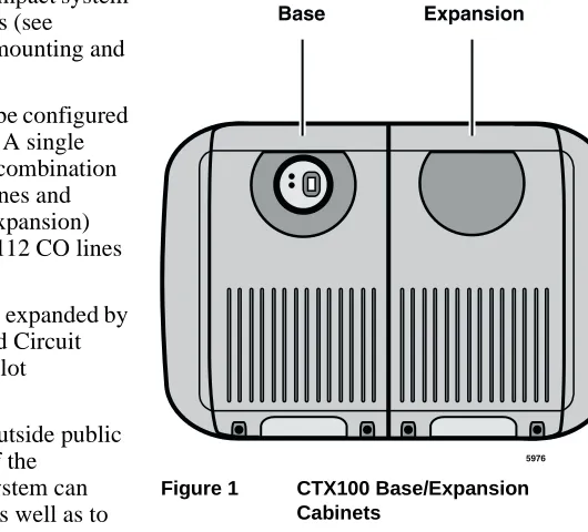
The Strata CTX100 system is a compact system that provides large system features (see
Figure 1). It is designed for wall mounting and occupies very little space.
The CTX100 basic processor can be configured with a one or two cabinet system. A single (Base) cabinet system supports a combination of up to 64 Central Office (CO) lines and stations, while a two (Base and Expansion) cabinet system can support up to 112 CO lines and stations.
System line and station capacity is expanded by adding CO line and station Printed Circuit Boards (PCBs) into its universal slot architecture.
The CTX100 easily connects to outside public and private telephone lines. All of the
telephones (stations) tied to the system can have direct access to each other, as well as to the public and private network.
Each CTX100 system has a Base Cabinet with one optional Expansion Cabinet. All lines, stations, and options are tied together through the cabinets. The overall weight and dimensions of the
CTX100 cabinets are shown in Table 1.
Table 1 CTX100 Cabinet Specifications
Cabinet Weight1
1. Weight includes the processor PCB in the Base Cabinet and four universal PCBs in each cabinet.
Height Width Depth
Base Cabinet (CHSUB112) 19.4 lbs. 14.6 in. 11.9 in. 10.2 in. Base + Expansion Cabinet
(CHSUE112) 34.6 lbs. 14.6 in. 19.9 in. 10.2 in.
5976
Base Expansion
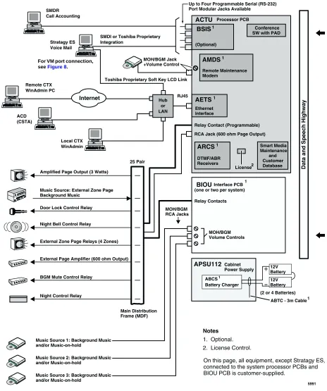
CTX100 Processor
CTX100 Processor
The system operates with one processor circuit board (ACTU) that installs in a dedicated slot of the Base Cabinet. The ACTU processor incorporates the following hardware features:
CPU/Memory
The CTX100 uses a high-speed, 32-bit, RISC processor, Dynamic Random Access Memory (DRAM) working memory, Static Random Access Memory (SRAM) with lithium battery for memory back-up, and flash program memory.
Large Scale Integrated (LSI) Circuits
The processor has LSI circuits that support the following:
• 16 DTMF receivers – requires ARCS and, for five or more DTMF receivers, requires
appropriate licenses. See “CTX100 License Control” on page 4.
• 16 Busy Tone (BT) detectors for Auto Busy Redial (ABR) – requires ARCS.
• 64 built-in conference circuits (see Table 7 on page 13 for more information).
• Built-in, adjustable, digital volume PAD technology enables audio volume to be adjusted in
eight steps to compensate for conference and/or CO line network losses.
Memory Protection Battery
If commercial AC power is lost or if a system is moved or stored without power, the processor has an on-board battery that protects data and the customer’s programmed configuration from memory loss. This information will be maintained in a powerless system for at least six years.
Relay Control Interface
An on-board terminal strip provides an interface to a normally open relay contact which can be programmed to control a Night Bell, door lock or to mute BGM during an external page.
External Page Interface
A 600 ohm RCA jack is built into the processor to interface with a Toshiba External Amplified Speaker (HESB) or a customer-supplied page amplifier and speaker(s) for external paging, night ring over external page, and external BGM applications.
Music-on-hold/Background Music Interface
A 600-ohm RCA jack and volume controls are built into the processor to interface with Music-on-hold and/or Background Music (BGM) sources (one of the jacks is for future use). With the CTX100, you can have up to 15 MOH/BGM source interfaces by adding:
• Up to two BIOU PCBs, each provides three MOH/BGM input sources
Strata CTX100 Overview
CTX100 Cabinet Slots
SmartMedia Memory
The processor has an on-board SmartMediaTM memory card slot. A SmartMedia flash memory
card can be inserted into the slot to backup and restore customer program data. It also makes it easy to upload operating system data for software upgrades and is used for maintenance functions
(see “System Fault Finding and Diagnostics” on page 67 for more details).
CTX100 Processor Optional Subassemblies
Optional subassemblies can be attached to the ACTU processor to provide additional features. The subassemblies are:
• AMDS (Modem) – Provides a 33.6Kbps/V.34 modem for point-to-point local or remote
connection to the CTX WinAdmin administration PC.
• ARCS (DTMF Receiver/Busy Tone Detector) – Provides 16 DTMF receivers maximum and
16 Auto Busy Redial (ABR), Busy Tone detectors maximum.
• AETS (Ethernet LAN Interface) – Provides one 10baseT Ethernet circuit with an RJ45
connector for CTI Open Architecture applications (future), CTX Attendant Console (future), ACD Server (future), Toshiba Proprietary Voice Mail integration and system administration connection (including local and remote CTX WinAdmin).
• BSIS (Serial Port Interface) – Provides up to two RS-232 interface ports for SMDR interface
to Call Accounting devices, SMDI or Toshiba Proprietary interface to Voice Mail devices, and two future applications.
CTX100 Cabinet Slots
Base Cabinet
The Base Cabinet has one dedicated slot used for the system processor PCB and four universal slots (S101~S104), that can accommodate station, line or option PCBs. It also houses a power supply that is packaged with the cabinet.
Expansion Cabinets
CTX100 License Control
CTX100 License Control
The system size and feature capability is controlled using a software License Key Code. This key code is obtained from Toshiba Internet FYI during the ordering process and is installed onto the system processor via Strata CTX WinAdmin. Processor license codes activate system hardware capacities in the following increments.
• The first 32 line/station ports do not require a license. Each additional set of four line/station
ports requires one LIC100-4 PORTS license (maximum of 112 ports).
• The optional DTMF receiver circuit (ARCS) provides 16 DTMF receiver hardware circuits and
16 ABR circuits. The first four DTMF circuits and all ABR circuits do not require a license. Each additional set of four DTMF receiver circuits requires one LIC100-4 DTMF license (maximum of 16 DTMF circuits).
Note DTMF tone receiver circuits are required for standard telephones, Voice Mail DTMF
integration, Tie, DID and DNIS line service.
• The optional RS-232 serial port interface (BSIS) provides two circuits to interface with SMDI
or Toshiba Proprietary Voice Mail integration, Call Accounting SMDR, and two for future applications. The first circuit does not require a license, but circuits two through four each require one LIC100-SER PORT license.
Licensed Software Options
Some software options are activated with license codes. The following software options require a license:
• Each CTX system (node) in a Strata Net QSIG Network requires one LIC100-QSIG NET
license. A maximum of four serial network nodes are allowed in any one serial chain in the network topology.
• The optional AETS PCB provides hardware LAN interface for all CTI Open Architecture
Strata CTX670 Overview
2
The Strata CTX670 system provides sophisticated telecommunication features in a modular system designed for growth. Its universal slot architecture enables you to select the combination of Central Office (CO) lines, stations, and peripheral options that best suit your needs.
The CTX670 basic processor can be configured for smaller systems as a one or two cabinet system with a capacity of up to 192 CO lines and stations combined. It can expand to support up to seven cabinets with a capacity of up to 672 CO lines and stations combined
(see Figure 2).
System line and station capacity is expanded by adding processor expansion Printed Circuit Boards (PCBs), cabinets and line/station PCBs.
The CTX670 easily connects to outside public and private telephone lines. All of the telephones (stations) tied to the system can have direct access to each other as well as to the public and private network.
The Base Cabinet and optional Expansion Cabinets are the building blocks of the system. Each system has a Base Cabinet, and can have from one to six Expansion Cabinets. All lines, stations, and options are tied together through the cabinets.
The overall weight and dimensions of the CTX670 cabinets are shown in Table 2.
Table 2 CTX670 Cabinet Specifications
Cabinet Weight Height Width Depth
Base Cabinet (CHSUB672) 31 lbs. 11.625 in. 26.5 in. 10.3 in. Expansion Cabinet (CHSUE672) 29 lbs. 9.75 in. 26.5 in. 10.3 in.
5398
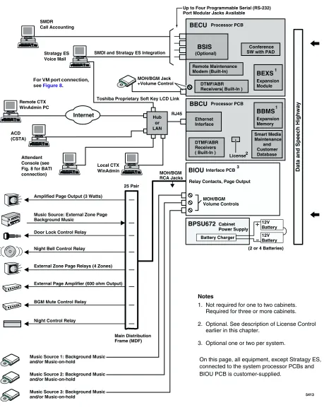
CTX670 Processor PCBs
CTX670 Processor PCBs
The system operates with one set of processor PCBs (BECU/BBCU) that install in dedicated slots of the Base Cabinet. The BECU/BBCU processor incorporates the following on-board hardware features:
CPU/Memory
The CTX670 uses a high-speed, 32-bit, Reduced Instruction Set Computing (RISC) processor, Dynamic Random Access Memory (DRAM) working memory, Static Random Access Memory (SRAM) with lithium battery for back-up memory, and flash program memory.
Large-scale Integrated (LSI) circuits
The processor has LSI circuits that support the following:
• 16 built-in DTMF receivers; 32 available using the BEXS. For five or more DTMF receivers,
appropriate licenses are required. See “CTX670 License Control” on page 7.
• 16 built-in Busy Tone (BT) detectors for Auto Busy Redial (ABR); 32 available using the
BEXS
• 64 built-in conference circuits; up to 96 conference circuits are available using the BEXS. (See
Table 7 on page 13 for more information).
• Built-in, adjustable, digital volume PAD technology enables audio volume to be adjusted in
eight steps to compensate for conference and/or CO line network losses.
Memory Protection Battery
If commercial AC power is lost or if a system is moved or stored without power, the processor has an internal battery that protects data and the customer’s programmed configuration from memory loss. This information will be maintained in a powerless system for at least six years.
Music-on-hold/Background Music Interface
An RCA jack and volume control are built into the processor to interface with a Music-on-hold and/ or Background Music source. With the CTX670, you can have up to 15 MOH/BGM sources by adding:
• Up to two BIOU PCBs, each provides three MOH/BGM input sources
• An RSTU PCB that provides up to eight MOH/BGM input sources
SmartMedia Memory
The processor has an on-board SmartMedia card slot. A SmartMedia flash memory card can be inserted to backup and restore customer program data. It also makes it easy to upload operating
system data for software upgrades and is used for maintenance functions (see “System Fault
Strata CTX670 Overview
CTX670 License Control
Network Interface
The processor has an on-board Ethernet 10Base-T Ethernet circuit for connection to Open Architecture Computer Telephony Interface (CTI) applications. This provides extensive call control and telephone support for CTI applications. The Ethernet Network Interface Card (NIC) port also enables connection to the following:
• CTX Attendant Console (future)
• ACD server (future)
• Local and Remote CTX WinAdmin PC
• Soft Key Control of Voice Mail features
Maintenance Modem
A built-in maintenance modem (33.6Kbps/V.34) on the processor can provide point-to-point local or remote connection to the CTX WinAdmin administration software.
CTX670 Processor PCB Subassemblies
Subassemblies can be added to the processor PCBs to enable system expansion and provide additional features. The subassemblies are:
• BEXS and BBMS expansion PCBs mount onto the processor PCBs to provide increased port
capacity, from Basic (192 ports) to Expanded (672 ports). The BEXS provides switching capacity, and the BBMS provides memory capacity. For Basic and Expanded capacities of
stations, lines and features, see Tables 3~7. To expand the system, both subassemblies must be
installed.
• BSIS interface PCB which attaches to the BECU to provide up to four RS-232 interface ports
for SMDR Call Accounting and SMDI or Toshiba Proprietary Voice Mail interface.
See Table 3 on page 11 for the number of cabinets and universal PCB slots for the Basic and Expanded systems.
CTX670 License Control
The system size and feature capability is controlled using a software License Key Code. This key code is obtained from the Toshiba Internet FYI site during the ordering process and is installed onto the system processor via Strata CTX WinAdmin. Processor license codes activate system hardware capacities in the following increments.
• The first 64 line/station ports do not require a license. Each additional set of four line/station
ports requires one LIC670-4 PORTS license (maximum of 672 ports).
• The on-board DTMF receiver circuit provides up to 32 DTMF receiver hardware circuits. The
first four DTMF circuits do not require a license. Each additional set of four DTMF receiver circuits requires one LIC670-4 DTMF license (max. total of 32 DTMF circuits).
Note DTMF tone receiver circuits are required for standard telephones, Voice Mail DTMF
integration, Tie, DID and DNIS line service.
• The optional RS-232 serial port interface (BSIS) provides two circuits to interface with Voice
CTX670 Cabinet Slots
Licensed Software Options
Some software options are activated with license codes. The following software options require a license:
• Each CTX system (node) in a Strata Net QSIG Network requires one LIC670-QSIG NET
license. A maximum of four serial network nodes are allowed in any one serial chain in the network topology.
• Each individual CTI Open Architecture application (future) requires one LIC670-CSTA AP
license (maximum nine).
CTX670 Cabinet Slots
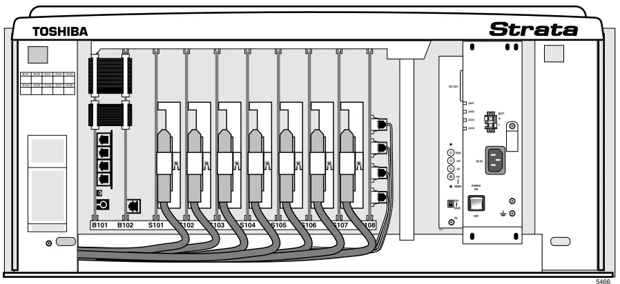
Base Cabinet
The Base Cabinet has two dedicated slots used for the system processor PCBs and eight universal
slots, labeled “S101~S108,” that can accommodate station, CO line or option PCBs (see Figure 3).
It also houses a power supply.
Figure 3 Base Cabinet Interior
POW +5V -5V P.F.
RESET
EXP BASE
AC IN BATT DC OUT
-24V1 -24V2 -24V3 -24V4
+
-POWER ON
OFF FG
5002 B101 B102 S101 S102 S103 S104 S105 S106 S107 S108
5466
B101 B102S101S102S103
Strata CTX670 Overview
CTX670 Remote Expansion Cabinet
Expansion Cabinets
One to six Expansion Cabinets can be added to increase the system station and CO line capacity.
Each expansion cabinet provides 10 slots (S_01~S_10). Figure 4 shows an Expansion Cabinet.
Refer to the following section for cabinet slot and station/line capacities. Tables 4 and 5 show the
number of stations and CO lines allowed when additional cabinets and PCBs are used.
CTX670 Remote Expansion Cabinet
A CTX670 Expansion Cabinet can be located up to three kilometers from its Base Cabinet. Remote Expansion Cabinets are enabled by the RRCU PCB. One RRCU connects to up to two ribbon-type Data Cables and applies the inter-cabinet signal to a multi-mode fiber-optic pair. One fiber pair can support one or two expansion cabinets in one remote location using one RRCU in the Base Cabinet and another in the Remote Expansion Cabinet.
The CTX670 Base Cabinet supports up to six Remote Expansion Cabinets (at least one RRCU PCB is required for each remote location).
Remote cabinets support the BIOU for external Page Zones, Night Bell, etc., and all CO line and trunk interface PCBs. Network clock synchronization can only be derived from digital trunks installed in the Base Cabinet (Master) location.
S_01 S_02 S_03 S_04 S_05 S_06 S_07 S_08 S_09 S_10
5003
CABINET NO. 2
S_01S_02 S_03S_04S_05 S_06S_07 S_08S_09S_10
3 4 5 6 7
POW +5V -5V P.F. RESET
EXP BASE
AC IN AC IN DC OUT
-27V1 -27V2 -27V3 -27V4
+
-POWER ON
OFF FG
5002
POW +5V -5V P.F. RESET
EXP BASE
AC IN BATT DC OUT
-27V1 -27V2 -27V3 -27V4
+
-POWER ON
OFF FG
5002
Capacities
3
This chapter contains Strata CTX100 and CTX670 capacities for stations and peripherals, CO lines, station buttons and system features. All tables apply to both systems unless otherwise noted.
System Capacities
Important! The maximum capacities listed for the CTX100 in Tables 3~7 are based on an expanded CTX100 (Base + Expansion cabinet).
Table 3 Cabinet and Slot Capacities
Cabinets/Slots/Ports CTX100
CTX670 Basic Processor
BBCU + BECU
CTX670 Expanded Processor
BBCU + BECU + BEXS + BBMS
Cabinets 1 or 2 1 to 2 1 to 7
Universal slots 4 or 8 8 or 18 8 to 68
Maximum capacity of ports
(lines + stations) 112 192 672
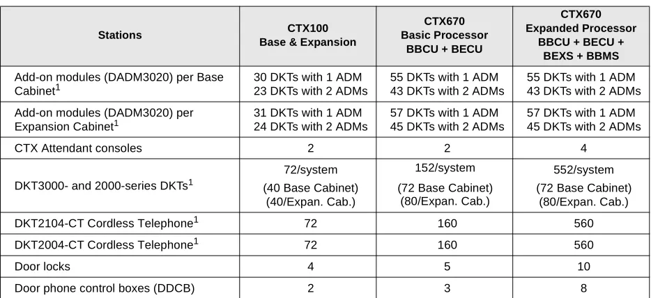
Table 4 Station/Peripherals System Capacities
Stations CTX100
Base & Expansion
CTX670 Basic Processor
BBCU + BECU
CTX670 Expanded Processor
BBCU + BECU + BEXS + BBMS
Add-on modules (DADM3020) per Base Cabinet1
30 DKTs with 1 ADM 23 DKTs with 2 ADMs
55 DKTs with 1 ADM 43 DKTs with 2 ADMs
55 DKTs with 1 ADM 43 DKTs with 2 ADMs
Add-on modules (DADM3020) per Expansion Cabinet1
31 DKTs with 1 ADM 24 DKTs with 2 ADMs
57 DKTs with 1 ADM 45 DKTs with 2 ADMs
57 DKTs with 1 ADM 45 DKTs with 2 ADMs
CTX Attendant consoles 2 2 4
DKT3000- and 2000-series DKTs1
72/system (40 Base Cabinet)
(40/Expan. Cab.)
152/system
(72 Base Cabinet) (80/Expan. Cab.)
552/system (72 Base Cabinet)
(80/Expan. Cab.)
DKT2104-CT Cordless Telephone1 72 160 560
DKT2004-CT Cordless Telephone1 72 160 560
Door locks 4 5 10
System Capacities
Door phones 6 9 24
DSS consoles (DDSS) 3 5 16
ISDN BRI station circuits TE-1 and TA
(2B+D per circuit) 12 28 96
Off-premise stations 72 160 560
BPCI used for TAPI only: per cabinet1 35 66 66
Total Stations (Digital/Analog/ISDN BRI B
channel combined) 72 160 560
Standard stations 64 160 560
Calls existing at the same time 56 96 366
1. Limit is based on cabinet Power Factor (PF).
Table 5 Line Capacities and Universal PCB Slots
Lines CTX100
Base & Expansion
CTX670 Basic Processor BBCU + BECU
CTX670 Expanded Processor BBCU + BECU +
BEXS + BBMS
CO lines – loop start
(analog - 8 lines/slot) 64 96 264
CO lines – ground start
(analog - 4 lines/slot) 32 72 264
DID lines (analog - 4 lines/slot) 32 72 264
Tie lines (analog - 4 lines/slot) 32 72 264
VoIP lines (4 lines/slot)1
1. Capacity is limited by FCC, Part 15, ElectroMagnetic Compatibility (EMC) restrictions.
8 20 20
T1 lines (DS-1)2
2. T1 lines can be loop start, ground start, Tie or DID (maximum 24 lines per unit, any type or combination).
64 96 264
ISDN BRI B channel lines3
3. BRI lines provide CO line services, including Caller ID, DID and Direct Inward Lines (DIL).
64 96 256
ISDN PRI B channel lines4
4. PRI lines provide CO line services, including QSIG Networking, Calling Party Number/Name, DID, Tie, POTS, FX and DIT.
48 96 264
Total lines (Analog, T1, ISDN BRI and
PRI B channels combined) 64 96 264
Channel Groups 32 48 128
Number of groups with Group CO Line
buttons 32 50 128
Table 4 Station/Peripherals System Capacities (continued)
Stations CTX100
Base & Expansion
CTX670 Basic Processor
BBCU + BECU
CTX670 Expanded Processor
Capacities
System Capacities
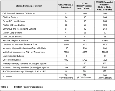
Table 6 Station Buttons
Station Buttons per System CTX100 Base & Expansion
CTX670 Basic Processor
BBCU + BECU
CTX670 Expanded Processor BBCU + BECU + BEXS + BBMS
Call Forward, Personal CF Buttons 72 160 560
CO Line Buttons 64 96 264
Group CO Line Buttons 64 96 264
Pooled CO Line Buttons 32 50 128
CO Group and Pooled Line Buttons 64 96 264
Station Loop Buttons 8 15 50
Door Unlock Buttons 4 8 16
Flexible Telephone Buttons 1600 3500 12000
Line Buttons in use at the same time 1440 3200 3200
Message Waiting Registration (DNs with MW) 130 230 800
Multiple Appearances of DNs on Telephones 2000 4000 12000
Night Transfer Buttons 2 4 8
One Touch Buttons 800 1750 6000
Primary Directory Numbers [PDNs] per system 72 160 560
Phantom Directory Numbers [PhDNs] per system 288 640 2240
[PhDNs] with Message Waiting Indication LED 18 38 128
ISDN DNs 96
(8 DNs/station)
224 (8 DNs/station)
768 (8 DNs/station)
Table 7 System Feature Capacities
Features CTX100 Base &
Expansion
CTX670 Basic Processor
BBCU + BECU
CTX670 Expanded Processor BBCU + BECU + BEXS + BBMS
Pilot DNs 100 200 256
Advisory LCD Messages (Set on a Telephone) 1 1 1
Advisory LCD Messages Lists (per System) 10 10 10
Attendant Groups 1 1 1
Call Accounting SMDR Interface1 1 1 1
Call Forward, System CF Patterns 4 10 32
Call Park Orbits (General) 14 32 64
Call Park Orbits (Individual) 56 96 336
Caller ID/ANI/CNIS Numbers stored (Call History records)
Up to 100/
station Up to 100/station Up to 100/station Up to 660/
system Up to 1000/system Up to 2000/system
CO Line Groups - Incoming Line Groups (ILG) 32 50 128
CO Line Groups - Outgoing Line Groups (OLG) 32 50 128
Outgoing Line Groups (OLG) Members per system
System Capacities
Conference Circuits 64 64 96
Conferencing (three-parties simultaneously)2 20 21 21
Conferencing (eight-parties simultaneously)2 8 8 12
Conference Party types (up to 8 total lines + stations) 8 stations max.6 lines max. 6 lines max. 8 stations max.
6 lines max. 8 stations max. Two-CO Line Conferencing – simultaneously2
(Two party only, no telephone or VM port) 32 48 132
Conference/Line Volume Adjustment (PAD) Groups 6 10 32
DID Numbers for Calling Number Identification/system 225 500 1000
DNIS/DID Network Routing Numbers 200 400 1000
DNIS/DID Numbers 450 1000 2000
DTMF Receivers3 16 16 32
E911 Groups 8 8 8
Emergency Call Groups 8 8 8
Hunt Groups (Serial/Circular/Distributed combined) 90 200 640
Hunt Group Size (DNs per group) 72 160 560
Hunt Group Stations (per system) 360 800 2800
ISDN DNs 96 224 768
ISDN Line Service Indexes 32 48 128
Night Bell Control Relay4 1 1 1
Night Transfer Control Relay4 1 1 1
Off-hook Call Announce Handsets (simultaneous) 20 21 31
Off-hook Call Announce to Telephone Speakers 5 72 112 352
Page Mute External BGM Control Relay4 1 1 1
Page Zone Relays4 8 8 8
Page Groups (Telephones with or without External Zones) 4 6 16
Paging – (Group Paging – simultaneous stations paged) 72 120 120
Pickup Groups 5 10 32
Ring Tones (External Call Ring Tones for digital phones) 4 4 4
Ring Tones (Internal Call Ring Tones for digital phones) 1 1 1
Speed Dial - Station SD numbers per system6 1080 2400 5600
Speed Dial - System SD numbers per system 800 800 800
Stratagy DK Voice Mail Systems per system 1 1 1
Tenants 1 1 1
Destination Restriction Level (DRL) Classes 16 16 16
Verified Account Codes 135 300 1000
Voice Mail SMDI Interface1 1 1 1
1. SMDI and SMDR require BSIS serial port interface.
2. Conference circuits are used dynamically, so the maximum number of simultaneous conferences is affected by the number of conference members in each conference. The total number of members in simultaneous conferences cannot exceed the total number of conference circuits. Each conference can have up to eight members.
3. DTMF receivers are required for standard touch tone telephones, voice mail integration, Tie, DID and DISA lines.
4. An option BIOU is required for up to four zone page relays and four control relays on the CTX100 and CTX670. One control relay is provided on board the CTX100 processor.
5. Speaker OCA capacity is determined by 2B channel slot availability and power supply. Requires BVSU option in telephone. 6. Up to 100 Station SD numbers, allocated in increments of 10, can be programmed per station.
Table 7 System Feature Capacities (continued)
Features CTX100 Base &
Expansion
CTX670 Basic Processor
BBCU + BECU
Capacities
CTX100 Maximum Capacity Configuration Examples
CTX100 Maximum Capacity Configuration
Examples
Table 8 CTX100 Base Cabinet with Digital Telephones and Loop Start Line With or Without Caller ID
Table 9 CTX100 Base and Expansion Cabinet with Analog Loop Start Lines
Table 10 CTX100 Base Only: Digital Telephones and T1 and/or PRI lines 4 Universal Slots
40 Stations (Max.) 24 CO lines (Max.)
44 Stations + Analog loop start lines combined (Max.) Stations Analog loop start lines
40 4 (none can have Caller ID) 32 8 (all can have Caller ID) 32 16 (none can have Caller ID) 16 16 (8 can have Caller ID) 241
1. Using ADKU.
8 (none can have Caller ID)
8 Universal Slots 72 Stations (Max.) 56 CO lines (Max.)
92 Stations + Analog Loop Start Lines combined (Max.) Stations Analog loop start lines
72 20 (none can have Caller ID) 72 16 (8 can have Caller ID) 64 32 (none can have Caller ID) 64 24 (8 can have Caller ID) 64 16 (all can have Caller ID) 48 40 (none with Caller ID) 48 32 (8 can have Caller ID) 48 24 (16 can have Caller ID) 32 48 (none can have Caller ID) 32 40 (8 can have Caller ID) 32 32(16 can have Caller ID) 32 24 (24 can have Caller ID) 16 32 (24 can have Caller ID)
4 Universal Slots 40 Stations (Max.)
48 lines (Max.)
64 Stations + T1 and/or PRI lines combined (Max.)
Stations T1 and/or PRI lines
40 24/23
32 40/40
CTX100 Maximum Capacity Configuration Examples
Table 11 CTX100 Base and Expansion Digital Telephones and with T1 and/or PRI lines
Table 12 CTX100 Base Cabinet Only with Analog Tie, DID and /or Ground Start Lines
Table 13 CTX100 Base and Expansion Cabinet with Analog Tie, DID and/or Ground Start Lines 8 Universal Slots
72 Stations (Max.) 64 lines (Max.)
112 Stations + T1 and/or PRI lines combined (Max.)
Stations T1 and/or PRI lines1
1. PRI lines are limited to 48B channels.
72 40/40
64 48/48
56 56/48
48 64/48
4 Universal Slots 40 Stations (Max.) 16 CO lines (Max.)
40 Stations + Analog Tie, DID, Ground Start Lines combined (Max.)
Stations Analog Tie, DID, and/or Ground Start Lines
40 4 line (Ground Start only) 32 8 lines (4 Tie/DID max.). 24 8 line any type 16 12 line any type
0 16 line any type
8 Universal Slots 72 Stations (Max.) 32 CO lines (Max.)
80 Stations + Analog Tie, DID and/or ground start Lines combined (Max.)
Stations Analog Tie, DID, and/or Ground Start Lines
Universal Slot PCBs
4
Universal Printed Circuit Boards (PCBs) installed in the Strata CTX100 or CTX670 cabinets provide interfaces for stations, lines, and peripherals. Each PCB measures 7.5 x 5.5 inches (190 x 140 mm) and mounts in the slot with a 44-pin backplane connector. PCB external connections to station equipment are made to the Main Distribution Frame (MDF) using industry-standard connectors.
Station, Line and Option PCBs
The PCBs are categorized as station, CO line or option PCBs (see Tables 14~16). Feature
subassemblies that plug onto a universal slot PCB, such as the Standard Telephone Interface Subassembly (RSTS), are listed below the associated PCB. For further details, refer to the Strata
CTX I&M Manual.
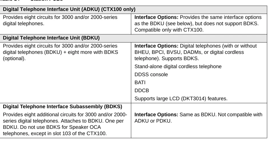
Table 14 Station PCBs
Digital Telephone Interface Unit (ADKU) (CTX100 only)
Provides eight circuits for 3000 and/or 2000-series digital telephones.
Interface Options: Provides the same interface options
as the BDKU (see below), but does not support BDKS. Compatible only with CTX100.
Digital Telephone Interface Unit (BDKU)
Provides eight circuits for 3000 and/or 2000-series digital telephones (BDKU) + eight more with BDKS (optional).
Interface Options: Digital telephones (with or without
BHEU, BPCI, BVSU, DADMs, or digital cordless telephone). Supports BDKS.
Stand-alone digital cordless telephone DDSS console
BATI DDCB
Supports large LCD (DKT3014) features.
Digital Telephone Interface Subassembly (BDKS)
Provides eight additional circuits for 3000 and/or 2000-series digital telephones. Attaches to BDKU. One per BDKU. Do not use BDKS for Speaker OCA
telephones, except in slot 103 of the CTX100.
Interface Options: Same as BDKU. Not compatible with
Station, Line and Option PCBs
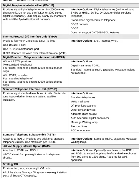
Digital Telephone Interface Unit (PDKU2)
Provides eight digital telephone circuits (2000-series phones only. Do not use the PDKU for 3000-series digital telephones.). LCD display is only 16 characters wide and the 6SGLDO button will not work.
Interface Options: Digital telephones (with or without
BHEU or HHEU, DVSU, DADMs, or digital cordless telephone)
Stand-alone digital cordless telephone DDSS console
DDCB
Does not support DKT3014-SDL features.
Internet Protocol (IP) Interface Unit (BVPU)
Provides four VoIP Circuits as E&M Tie lines One 10Base-T port
One RS-232 maintenance port
H.323 standard for Voice over Internet Protocol (VoIP).
Interface Options: LAN, Internet, WAN.
Digital/Standard Telephone Interface Unit (RDSU)
Without RSTS, provides: Two standard telephone/
Four digital telephone circuits (2000-series phones only).
With RSTS, provides: Four standard telephone/
Four digital telephone circuits (2000-series phones only).
Interface Options:
Digital – same as PDKU.
Standard – same as RSTU (standard Message Waiting not available)
Standard Telephone Interface Unit (RSTU3)
Provides eight standard telephone circuits. Stutter dial tone is provided for Message Waiting audible
indication.
Interface Options:
Standard telephones Voice mail ports Off-premises stations Other similar devices Alternate BGM source
Auto Attendant digital announcer Message Waiting lamp
Fax machines ACD Announcer
Standard Telephone Subassembly (RSTS)
Attaches to RDSU. Provides two additional standard telephone circuits. One maximum per RDSU.
Interface Options: Same as RSTU, except no Message
Waiting lamp.
-48 Volt Supply Internal Option (R48S)
Attaches to RSTU and RDSU
48VDC circuit for up to eight standard telephone circuits.
Interface Options: Optionally interfaces to the RSTU
and RDSU to extend loop length of standard telephones from 600 ohms to 1200 ohms. Required for OPS operation.
Stratagy DK
Provides two, four, six, or eight VM ports.
All of the above Stratagy DK systems use eight station ports of Strata CTX capacity.
Universal Slot PCBs
Station, Line and Option PCBs
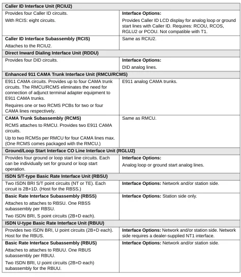
Table 15 CO Line PCBs Caller ID Interface Unit (RCIU2)
Provides four Caller ID circuits. With RCIS: eight circuits.
Interface Options:
Provides Caller ID LCD display for analog loop or ground start lines with Caller ID. Requires: RCOU, RCOS, RGLU2 or PCOU. Not compatible with T1.
Caller ID Interface Subassembly (RCIS)
Attaches to the RCIU2.
Same as RCIU2.
Direct Inward Dialing Interface Unit (RDDU)
Provides four DID circuits. Interface Options:
DID analog lines.
Enhanced 911 CAMA Trunk Interface Unit (RMCU/RCMS)
E911 CAMA circuits. Provides up to four CAMA trunk circuits. The RMCU/RCMS eliminates the need for connection of adjunct terminal adapter equipment to E911 CAMA trunks.
Requires one or two RCMS PCBs for two or four CAMA lines respectively.
E911 analog CAMA trunks.
CAMA Trunk Subassembly (RCMS)
RCMS attaches to RMCU. Provides two E911 CAMA circuits.
Up to two RCMSs per RMCU for four CAMA lines max. (One RCMS comes packaged with the RMCU.)
Same as RMCU.
Ground/Loop Start Interface CO Line Interface Unit (RGLU2)
Provides four ground or loop start line circuits. Each can be individually set for ground or loop start operation.
Interface Options:
Analog loop or ground start analog lines.
ISDN S/T-type Basic Rate Interface Unit (RBSU)
Two ISDN BRI S/T point circuits (NT or TE). Each circuit is 2B+1D. (Host for the RBSS.)
Interface Options: Network and/or station side.
Basic Rate Interface Subassembly (RBSS)
Attaches to attaches to RBSU. One RBSS subassembly per RBSU.
Two ISDN BRI, S point circuits (2B+D each).
Interface Options: Station side only.
ISDN U-type Basic Rate Interface Unit (RBUU)
Provides two ISDN BRI, U point circuits (2B+D each). Host for the RBUS.
Interface Options: Network and/or station side. Network
side requires a dealer-supplied NT1 interface.
Basic Rate Interface Subassembly (RBUS)
Attaches to attaches to RBUU. One RBUS subassembly per RBUU.
Two ISDN BRI, U point circuits (2B+D each) subassembly for the RBUU.
Station, Line and Option PCBs
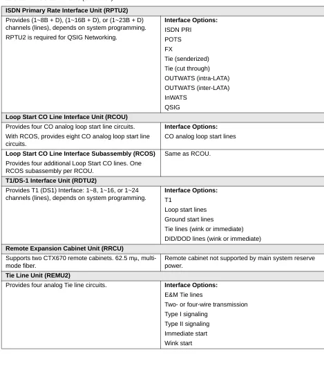
ISDN Primary Rate Interface Unit (RPTU2)
Provides (1~8B + D), (1~16B + D), or (1~23B + D) channels (lines), depends on system programming. RPTU2 is required for QSIG Networking.
Interface Options:
ISDN PRI POTS FX
Tie (senderized) Tie (cut through) OUTWATS (intra-LATA) OUTWATS (inter-LATA) InWATS
QSIG
Loop Start CO Line Interface Unit (RCOU)
Provides four CO analog loop start line circuits. With RCOS, provides eight CO analog loop start line circuits.
Interface Options:
CO analog loop start lines
Loop Start CO Line Interface Subassembly (RCOS)
Provides four additional Loop Start CO lines. One RCOS subassembly per RCOU.
Same as RCOU.
T1/DS-1 Interface Unit (RDTU2)
Provides T1 (DS1) Interface: 1~8, 1~16, or 1~24 channels (lines), depends on system programming.
Interface Options:
T1
Loop start lines Ground start lines
Tie lines (wink or immediate) DID/DOD lines (wink or immediate)
Remote Expansion Cabinet Unit (RRCU)
Supports two CTX670 remote cabinets. 62.5 mµ, multi-mode fiber.
Remote cabinet not supported by main system reserve power.
Tie Line Unit (REMU2)
Provides four analog Tie line circuits. Interface Options:
E&M Tie lines
Two- or four-wire transmission Type I signaling
Type II signaling Immediate start Wink start
Table 16 Option PCBs
Option Interface Unit (BIOU) Interface Options:
Provides Paging output (600 ohm and three-watt amp), four zone paging relays, three MOH interfaces and four control relays (Night Transfer and BGM mute).