A&
HP *
c
Table of Contents
PAGE SYSTEM FEATURE
Access to Paging.. ... Account Codes: Forced, Verifiable, Voluntary.. ... Alphanumeric Trunk ID ... Call Forward Busy (System/DID) ... Call Forward Busy/No Answer (System/DID). ... Camp-on ... Class of Service Restrictions ... Common Control Switching Arrangement Access.. ... Consoleless Operation ... Data Transmission-Voice Band ... Dialed Number Identification Service (DNIS) ... Direct-in Line.. ... Direct-in Line Pooling (Delayed Ringing). ... Direct Inward Dialing ... Distinctive Ringing ... Emergency Ringdown ... Flexible Numbering ... Immediate Ringing ... Intercept ... Least Cost Routing (LCR). ... Least Cost Routing Enhancement for “011” ... Line Lockout ... ... Message Center ... Multiple Console Operation ... Multiple Trunk Groups.. ... Music-on-Hold and Camp-on ... Night Operator Station ... Night Service ... Off-premises Stations ... Power Failure/Emergency Transfer ... Remote Access to Services ... Remote Administration/Maintenance.. ... Rotary Dial Compatibility ... Route Advance ... Station Message Detail Recording (SMDR) ... Station Set Mix ... Ti Interface ... Tandem Switching ... Tenant Service ... -TIE Trunks. ... Toll Restriction (6-digit) ... Toll Restriction/Class of Service Override Code ... Tone Dialing ... Tone Dialing-to-Dial Pulse Conversion ... Traffic Measurement ... ... . Trunk Transfer Recall (Timer & Termination Destination) ... Uniform Distribution Wiring.. ... Universal Night Answer ... Universal Port Architecture ... Variable Time-out ... Voice Mail Connection ...
Table of Confenfs
SUBJECT PAGE
STATION FEATURES
Automatic Callback ... Automatic Wake-upnimed Reminder ... Call Forward-All Calls ... Call Forward-Busy ... Call Forward-Busy/No Answer.. ... Call Forward-No Answer ... Call Forward to Trunk ... Call Pickup-Directed ... Call Pickup-Group ... Call Transfer ... Call Waiting ... Conference (3-Patty with Transfer) ... Consultation Call ... Direct Outward Dialing ... Do Not Disturb ... Flash-Hook Timing.. ... Hold All Calls ... Maid-in-Room Status (Lodging/Health Care Only) ... Manual Line Service ... Meet-Me Page ... Message Waiting ... Off-hook Call Announce ... Outgoing Calls (DTA and LCR) ... Override (Executive) ... Park (Call Park) ... Private CO Line ... Remote Retrieval of Held Calls.. ... Repeat Last Number Dialed ... Saved Call Forwards and Message Waiting ... Speed Dialing ... Station Hunting ... Station-to-Station Calling ... Trunk-to-Trunk Connections ... Uninterrupted Line Connections ...
FIGURE
FIGURE LIST
2-1 2-4 2-5 2-8 2-11 2-14 2-17 2-19 2-20 2-22 2-23 2-26 2-30 2-31 2-32 2-34 2-35 2-37 2-39 2-40 2-41 2-43 2-46 2-47 2-49 2-51 2-54 2-55 2-56 2-57 2-61 2-64 2-65 2-67
SUBJECT PAGE
Call Forward-All Calls . . . 2-7 Call Forward-Busy . . . 2-10 Call Forward-Busy/No Answer . . . 2-13 Call Forward-No Answer . . . 2-16 Call Forward to Trunk . . . 2-18 Direct Connection Matrix . . . 2-66
Table of Contents
SUBJECT PAGE
ELECTRONIC/DIGITAL TELEPHONE FEATURES
Alphanumeric Message Display ... Automatic Dialing.. ... Automatic Line Preference ... Call Status Indication ... Common Audible Signaling ... End-to-End Signaling.. ... Fixed Automatic Dialing Buttons.. ... Handsfree Answerback with Speaker Cut-off.. ... Handsfree Monitoring ... Liquid Crystal Display ... Manual Signaling ... Modular Line and Handset Cords.. ... Multiple-appearance Directory Number.. ... Non-locking Buttons.. ... On-hook Dialing ... Prime Directory Number.. ... Privacy ... Privacy Release.. ... Push-button Access to Features.. ... Push-button Dialing ... Release.. ... Speaker/Amplifier ... Speakerphone ... Station-to-Station Messaging.. ... Summary of LCD Functions.. ... Tone Buzzing ... Tone Ringing.. ... Voice Paging.. ... Volume Controls ...
ATTENDANT CONSOLE FEATURES
Attendant Camp-on/Call Waiting ... Attendant Conference.. ... . ... Attendant Emergency Transfer.. ... Attendant Hold ... Attendant Initialization ... Attendant Recall ... Busy Lamp Field.. ... Call Forward Cancel ... Call Waiting Lamp ... Call Waiting Lamp Signaling ... Digital Information Display.. ... Direct Access to Paging ... Incoming Call Identification ... Incoming Call Priority.. ... Individual Trunk Access.. ... Interposition Call Transfer.. ... Join ...
Table of Contents
SUBJECT PAGE
ATTENDANT CONSOLE FEATURES (Cont.)
Lockout ... Meet-Me Page ... Message Waiting ... Night Service Control ... Non-delayed Operation ... Overflow Facility ... Position Busy ... Push-button Dialing ... Secrecy ... Serial Call (Business Console Only) ... Speed Dialing-System ... Splitting. ... Station Number Display ... Switched Loop Termination ... Through Dialing ... Timed Recall-Variable ... Time-of-Day Display, Set, Reset ... Trunk Equipment Number Display ... Trunk Group Access Control ... Trunk Group Busy Indication ... Trunk-to-Trunk Connections.. ... ... Variable Attendant Console Loop Buttons.. ... Verification (Station & Trunk) ...
4-25 4-27 4-29 4-31 4-34 4-35 4-38 4-39 4-40 4-41 4-42 4-43 4-45 4-46 4-48 4-49 4-50 4-52 4-53 4-55 4-56 4-58 4-62
FIGURE LIST
FIGURE SUBJECT PAGE
1 Attendant Console With Four m Buttons . . . 4-59 2 Attendant Console With Six m Buttons . . . 4-60 3 Attendant Console With Eight m Buttons . . . . . 4-60
ATTENDANT-POSITION TELEPHONE FEATURES
Attendant-Position Electronic/Digital Telephone . . . 5-1
DIRECT STATION SELECTION CONSOLE (DSWDDSS) FEATURES
Direct Station Selection Console (DSS and DDSS) . . . 6-1
LODGING/HEALTH CARE FEATURES
Attendant Console ... 7-1 Automatic Wake-up/Timed Reminder ... 7-3 Clear the Maid-in-Room Status ... ... 7-5 Deposit Paid Confirmation ... 7-6 Emergency Ringdown ... 7-7 Executive Suite Telephone ... 7-8 Guest Room Information.. ... . ... 7-9
Table of Contents
SUBJECT LODGING/HEALTH CARE FEATURES (Cont.)
Maid-in-Room ... Message Registration ... Message Registration-Audit ... Message Registration-Room Display ... Message Waiting-Executive Suite Telephone ... Message Waiting-Guest Telephone. ... Outgoing Restriction ... Room/Number Correlation ... Room Status. ... Room Status Audit-BLF.. ... Room Status Audit-Printout ... Room-to-Room Blocking.. ... Set/Clear Do Not Disturb Room Status ...
PAGE 7-10 7-12 7-13 7-14 7-15 7-16 7-17 7-18 7-19 7-21 7-22 7-23 7-24
ACD/MIS FEATURES
ACD/MIS . . . . . . . . . ... ... 8-I
Multiple-Call Monitoring . . . 8-10
Multiple Overflow Destinations . . . 8-12
FIGURE LIST
FIGURE SUBJECT PAGE
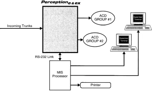
1 PERCEPTIONehex /MIS Interaction . . . 8-9
DATA FEATURES Analog Data Features
Automatic Callback ... Automatic Data Release ... Automatic Dialing ... Data Button ... Data Only Transmission ... Data Release Button ... Data Security Groups ... Data Switching Modes ... DDIU-MA Displays ... Do Not Disturb ... Modem Pooling ... Redial Last Number Dialed ... Simultaneous Voice and Data Transmission ... Speed Dialing ...
9-l 9-3 9-4 9-6 9-7 9-8 9-9 9-I 0 9-11 9-12 9-I 4 9-15 9-16 9-17 , NOTE: The above features relate to the DDIU-MA/MAT data units only.
Table of Contents
DATA FEATURES (Cont.) Digital Data Features
Automatic Callback ... Automatic Data Release ... Automatic Dialing ... Command Mode ... Communication Mode.. ... Data Button ... Data Call to PDIU-DI.. ... Data Call to PDIU-DS ... Data Release Button.. ... Data Security Groups ... Dialing Modifiers ... DIU Data Speed (Baud Rate) ... DIU Default Communication Parameters ... DIU Operation Modes ... Do Not Disturb ...
Incoming Data Call ... .:. ... Modem Pooling-Outgoing Data Call ...
PDIU-DI Buttons and LEDs ... PDIU-DS Displays ... Redial Last Number Dialed.. ... Result Codes ... S-Registers ...
Simultaneous Voice and Data Transmission ... Speed Dialing ...
Switching Between Modes ... NOTE: The above features relate to the PDIU-DUDS data units only.
APPENDIX A
9-20 9-22 9-23 9-25 9-27 9-28 9-29 9-31 9-32 9-33 9-34 9-35 9-36 9-37 9-38 9-40 9-41 9-43 9-44 9-45 9-46 9-47 9-48 9-50 9-53
APPENDIX B
Attendant Console and Attendant-Position Telephone with DSS Console
Comparative Capabilities . . . Appendix B-l
PERCEPTION
eaex
System Features
Table of Contents
FEATURE PAGE
Access to Paging ... Account Codes: Forced, Verifiable, Voluntary ... Alphanumeric Trunk ID ... Call Forward Busy (System/DID) ... Call Forward Busy/No Answer (System/DID) ... Camp-on ... Class of Service Restrictions ... Common Control Switching Arrangement Access.. ... Consoleless Operation ... Data Transmission-Voice Band.. ... Dialed Number Identification Service (DNIS) ... Direct-in Line.. ... Direct-in Line Pooling (Delayed Ringing). ... Direct Inward Dialing ... Distinctive Ringing ... Emergency Ringdown.. ... Flexible Numbering.. ... Immediate Ringing ... Intercept ... Least Cost Routing (LCR). ... Least Cost Routing Enhancement for “Oil”. ... Line Lockout ... Message Center.. ... Multiple Console Operation ... Multiple Trunk Groups.. ... Music-on-Hold and Camp-on.. ... Night Operator Station.. ... Night Service ... Off-premises Stations ... Power Failure/Emergency Transfer ... Remote Access to Services.. ... Remote Administration/Maintenance.. ... Rotary Dial Compatibility ... Route Advance ... Station Message Detail Recording (SMDR) ... Station Set Mix.. ... Tl Inter-face ... Tandem Switching ... Tenant Service ... TIE Trunks ... Toll Restriction (6-digit) ... Toll Restriction/Class of Service Override Code.. ... Tone Dialing ... Tone Dialing-to-Dial Pulse Conversion ... Traffic Measurement ... Trunk Transfer Recall (Timer & Termination Destination) ... Uniform Distribution Wiring.. ... Universal Night Answer ... Universal Port Architecture.. ... ... Variable Time-out.. ... Voice Mail Connection ...
Access to Paging
DESCRlPTlON This feature allows a station access to any one of the following: one external paging zone, all external paging zones, one internal paging group, the expanded internal paging group, or both the expanded internal paging group and all external paging zones.
OPERATION A paging access code is dialed in order to connect the station user directly to the paging system or the electronic/digital telephone speakers.
The attendant console’s m button can be assigned to access either the external zone(s) or internal zone(s).
To Page a Single External Zone: 1. Lift the handset.
n You will hear dial tone.
2. Press the m button, or dial the access code fli B) . W You will now be connected to the External Page zone. 3. Dial the desired paging zone number (0 - 4).
Paging Access Codes ZONE 1
ZONE 2 ZONE 3 ZONE 4 ZONE 5
Code Location
4. Announce your page.
H Speak slowly and distinctly, and repeat your message. To Page All External Zones:
1. Lift the handset.
H You will hear dial tone.
2A. Dial the access code <oII) .
n You will be connected to the External All-Page zone. . . . or . . .
2B. To page the Expanded Internal Paging Group in addition to all External Paging Zones, dial .
n You will be connected to the Expanded Internal Paging group and the External Paging zone.
3. Announce your page.
H Speak slowly and distinctly, and repeat your message. To Page a Single Internal Group:
I. Lift the handset.
n You will hear dial tone.
2. Press the m button, or dial the access code (EI 10) . H You will be connected to the Internal Paging zone.
Access to Paging
3. Dial the desired paging group number (2 - 17). 4. Announce your page.
n Speak slowly and distinctly, and repeat your message. To Page All Internal Groups:
1. Lift the handset.
n You will hear dial tone.
2A. Press the m button and dial 1 (the Internal All Paging Group number).
n You will now be connected to the Internal All Paging group. . . . or . . .
26. Dial the access code (0 1 PI .
n You will be connected to the Internal All Paging zone. . . . or . . .
2C. To page all External Paging Zones in addition to the Expanded Internal Paging Group, dial .
q You will be connected to all the External Paging zones and the Expanded Internal Paging group.
3. Announce your page.
n Speak slowly and distinctly, and repeat your message. To Page All Internal Groups and All External Zones:
1. Lift the handset.
n You will hear dial tone.
2. Dial the All Page access code . (This access code is defined in the DSYS Data Block.)
3. Hang up.
PROGRAMMING
1. Paging Zone access codes are assigned in the DACD Data Block. 2. The All Page access code is assigned in the DSYS Data Block. 3. The console’s m button is assigned in the DATT Data Block. 4. The DEKT Data Block is where EKT/DKT stations are assigned toInternal Paging groups. NOTES:
1. The External Paging control circuits are located on the NPRU PCB, which is part of the system’s standard equipment.
2. Station access to any or all Paging zones is determined by the station’s designated Class of Service.
3. DID, CCSA and TIE trunks cannot access Paging.
4. Paging cannot be accessed via Remote Access to Services (DISA). 5. With software versions prior to 0.02, PERCEPTION provides only the
five External Paging zones.
6. The attendant console preempts any station performing a page.
Access to Paging
RELATED FEATURES
1. Class of Service Restrictions (System). 2. Meet-Me Page (Station).BENEFITS
A
ccess to paging is convenient to the user since it permits the utilization of a system-incorporated paging unit and eliminates the need for external microphones. Additionally, the feature’s characteristic access-flexibility allows a station to access any or all Paging zones and groups, and thus eliminates the need for dedicated Paging positions.External Zone Paging enables the customer to make announcements over external loudspeakers that can be heard over a wide area. This feature is especially applicable to large, open, or noisy environments such as automobile dealerships, warehouses, or workshops. It can also be used in conjunction with Internal Group Paging, to provide the end-user with a Paging scheme customized to his or her unique requirements.
In Internal Group Paging, pages over the speakers in electronic/digital telephones are more private than zone pages. They can be made to specific groups of station users rather than physical locations. This feature is especially applicable to office environments, professional business such as law or accounting offices, and other applications in which low noise levels must be maintained. It can be used in conjunction with External Zone Paging, to provide the end-user with a Paging scheme customized to his or her unique requirements.
Account
Codes: Forced, Verifiable,
Voluntary
DESCRIPTION
Account codes enable the end-user to track both incoming and outgoing calls and then bill, allocate costs, or otherwise classify calls by type or purpose. The account code is entered either during a call, or immediately following it, and then included in the Station Message Detail Recording (SMDR) information for the call. The code can be printed out as part of an SMDR call record or, if a call accounting system is connected to PERCEPTION, manipulated as part of a customized call report. In this last case, calls can be sorted and analyzed using the entered account code as a primary variable. Typical uses of account codes include assigning billable telephone time to clients for professional services (attorneys, accountants, etc.); allocating expenses to internal cost centers for various types of business operations; classifying the nature or subject of a call for service or sales organizations.PERCEPTION gives the end-user the ability to choose between three types of account code entry:
1. Voluntary entry enables each telephone user to enter the codes when he or she deems it necessary on either incoming or outgoing calls.
2. Forced entry requires the telephone user to enter a code when making certain types of outgoing calls. (Account code entry cannot be forced on any incoming calls.) Unless the entered code is also
verified, once the appropriate number of digits has been entered, the call will automatically be completed. Forced entry can be applied to all calls, or to toll calls only. Toll calls apply to the following dialing sequence:
3. Verified entry enables any code entered on an outgoing call (either Forced or Voluntary) to be verified against a list of valid account codes programmed in the PERCEPTION data base. PERCEPTION automatically completes the call if the entered code is valid. If the entered code is not valid, PERCEPTION provides reorder tone to the caller and does not complete the call. If account code entry is forced and verifiable, PERCEPTION gives the caller three opportunities to enter a valid code before disconnecting the call. If account code entry is voluntary and verifiable, PERCEPTION will continue to provide reorder tone until the caller enters a valid code or overrides code entry.
Forced account codes, for all calls and/or forced toll calls only, and verified account codes can be combined so that a station user will be required to enter just one code. The code entered serves as both a forced and verifiable code. A station user gets three opportunities to enter a correct code before overflow tone is received.
Forced and Verified account code entry is controlled by a station’s Class of Service, and can be separately assigned for either all outgoing calls or for toll calls only.
Account
Codes: Forced, Verifiable,
Voluntary
Account codes can be from 1 to 12 digits in length, and PERCEPTION will only accept codes of the programmed length. There is no limit to the number of nonverified codes that can be entered. (Obviously, code length determines how many individual codes can be used-l 00 codes for a two- digit length, 1000 for three digits, etc.) Because verifiable codes utilize space in system memory, there are limits to the number of codes that can be verified based on digit length. The following matrix shows the maximum number of verifiable codes for each possible code length.
VERIFIABLE
ACCOUNT CODE MAXIMUMS
DIGITS 1 2 3 4 5, 6 7,8 9,10 11,12 CODES 10 100 1000 1500 1000 750 600 500 OPERATION T; R;;;;ea,;mwy Account Number Before Dialing a Call:
n You will hear dial tone.
2. Press the m button, or dial the access code (l B) . 3. Dial the account number on the dialpad (1 - 12 digits).
n When the number is completed, you will receive recall dial tone. 4. Dial the telephone number in the usual manner.
To Record a Voluntary Account Number During a Call (Incoming or Outgoing) Without a m Button:
At any time before disconnect . . . 1. Ask your party to wait. 2. Press the m button.
H Your connection will be placed on hold, and you will hear recall dial tone.
3. Dial the access code [I . n You will hear recall dial tone. 4. Dial the account number (1 - 12 digits).
n When the number is completed, you will hear recall dial tone again.
5. Press the appropriate
q
button.n You will be reconnected to your party. 6. Resume your conversation.
To Record a Voluntary Account Number During a Call (Incoming or Outgoing) With a m Button:
At any time before disconnect . . . 1. Ask your party to wait.
Account
Codes: Forced, Verifiable,
Voluntary
2. Press them button.
n The connection will be placed on hold, the DN LED indicates the On-hold status, and the CRG LED will light.
3. Dial the account number (1 - 12 digits).
H When the number is completed, the call will automatically be reconnected.
4. Resume your conversation
To Record a Forced, or a Forced and Verifiable Account Code (Direct Trunk Access or Least Cost Routing):
1. Access a CO line (by dialing the DTA or LCR access code). n You will hear dial tone.
2. Dial the distant directory number. H You will hear recall dial tone.
3. Using the dialpad, dial the l- - 12-digit account code (determined in the DMDR Program).
n The account code is saved
to output
to SMDR.H The system stores dialed directory number to auto-dial queue, and the trunk call is made.
NOTE: These Forced and Forced/Verifiable Account Codes can be applicable to either all calls or toll calls only (programming option).
To Record a Verifiable Account Code Before Dialing a Call: 1.
2. 3. 4.
Lift the handset.
H You will hear dial tone. Press them button.
Dial the I- - 12-digit account code on the dialpad. n You will hear recall dial tone.
Dial the Direct Trunk access code and the desired telephone number. 4 The trunk call is made.
To Record a Verifiable Account Code During a Call (Incoming or Outgoing) With am Button:
At any time during conversation . . . 1. Ask your party to wait.
2. Press the m button.
n You wil hear recall dial tone.
4 The connection will be placed on hold, the DN LED indicates the On-hold status, and the CRG LED will light.
3. Dial the l- - 12-digit account code.
n The system will store the account code to output to SMDR, and the call will automatically be reconnected.
’
Account
Codes: Forced, Verifiable,
Voluntary
To Record a Verifiable Account Code During a Call (Incoming or Outgoing) Without am Button:
At any time before disconnect . . .
1. Ask your party to wait, then press the m button. n You will hear recall dial tone.
2. Dial the CRG access code.
W Your connection will be placed on hold, and you will hear recall dial tone.
3. Dial the 1- - 12-digit account code.
n The system will store the account code to output to SMDR. 4. Resume your conversation.
To Record a Verifiable Account Code After a Call Is Completed:
This procedure applies when a station user forgets to input an account code either before, or during a call. The account code can still be entered after the call is completed, provided it is done prior to disconnecting the trunk.
After the call is completed
and
prior to the station user hanging up, the system automatically sets the ACT timer. Before the ACT timer expires . . .1. Press the m button or dial the CRG access code. H You will hear recall dial tone.
2. Dial the l- - 12-digit account code.
E The system sets the account code, the SMDR is printed out, and the line locks out.
3. Hang up.
PROGRAMMING This feature is available only with D.04 and later versions of software. 1. Forced and/or verifiable account
codes
are assigned to individualClasses of Service in the Class of Service (DCOS) Data Block. (No programming is required to permit stations to enter account codes on a voluntary basis.) A specific Class of Service is assigned to each station in either the Electronic/Digital Telephone (DEKT) or the Standard Telephone (DSTT) Data Block.
2. Account codes that PERCEPTION will verify are entered in the Verifiable Account Code (DVAC) Data Block. Verifiable account codes can be entered from the maintenance terminal (on-site or remotely),
an attendant console, or an attendant-position electronic/digital telephone.
3. Account code length (number of digits) is assigned in the Station Message Detail Recording (SMDR) Data Block. All valid account codes must be of this programmed number of digits in length. It does not matter what type of account codes are being used, a value MUST be entered in this data block for the feature to be enabled.
Account
Codes: Forced, Verifiable,
Voluntary
RELATED FEATURES
1. Station Message Detail Recording (System). 2. Class of Service (System).3. Toll Restriction/Class of Service Override Code (System).
BENEFITS
A
ccount codes give the end-user additional control over the operation of the telephone system. They enable additional revenue to be generated by accurately tracking billable telephone time on client calls. They also permit internal costs to be allocated among in-house cost centers for telephone expenses. And, they are flexible enough to allow the end-user to manipulate them in ways that serve the unique requirements of his or her application requirements.Alphanumeric
Trunk ID
DESCRIPTION
OPERATION
PROGRAMMING
RELATED FEATURES
BENEFITS
This feature enables the end-user to assign an alphanumeric name of up to 16 characters to each Central Office trunk connected to PERCEPTION. This name is displayed on the lower row of an electronic or digital telephone display while an incoming Central Office trunk call is ringing, and for ten seconds after it has been answered. If the call is forwarded, hunts, or is transferred, the name display follows the call to its final destination.
The name can be used to identify a company or person in an executive- suite application, or a product or sales promotion in an Automatic Call Distribution (ACD) or inbound call-center operation, or any other information important to the end-user. It provides the station user with important information about the call before it is actually answered.
This feature operates automatically once it is programmed.
This feature is available only with D.04 and later versions of software. Each Central Office trunk (Incoming, Outgoing, Bothway, WATS, and Foreign Exchange) can be programmed with an alphanumeric ID of up to 16 characters in the Trunk (DTRK) Data Block.
NOTE: An alphanumeric Trunk ID CANNOT be programmed for a DID or TIE trunk, or any trunk assigned as a private line. Alphanumeric Trunk ID can be assigned to Central Office trunks routed into PERCEPTION via Tl trunks.
Automatic Call Distribution (Automatic Call Distribution Features).
Alphanumeric Trunk ID provides station users with important information about an incoming trunk call before it is answered, enabling them to process the call more efficiently and more effectively. It is an especially important feature in Executive Suite and Automatic Call Distribution applications.
Cal/ Forward
Busy (System/DID)
DESCRlPTiON Call Forward Busy (System/DID) is used to automatically route incoming DID or CCSA calls, which encounter a busy tone at a station’s DID or CCSA directory number, to the attendant operator ONLY.
OPERATION To Use Call Forward Busy (System/DID): 1 A. Press the m button.
n The CFSB LED will flash.
2A. Dial 1 (the only number to which calls can be forwarded). 3A. Press the m button.
n The CFSB LED will light steadily. . . . or . . .
1 B. Lift the handset.
n You will hear dial tone.
2B. Dial the access code (IuB) . 1 You will hear recall dial tone. 3B. Dial 1.
4B. Dial 1.
n You will hear dial tone. 5B. Hang up.
PROGRAMMING TTn:eh~~~~D~D~~~~~~System/DID) feature access code is programmed NOTES:
1. If Call Forward Busy (System/DID) is restricted by a station’s Class of Service, then either the station will receive overflow tone (if the station utilizes a Call Forward Busy (System/DID) feature access code), or the station’s CFSB LED will not light (if the station utilizes a m button).
2. If an attendant dials the Call Forward cancel code, all Call Forward information which is currently registered within the system, will be canceled.
3. Calls may originate from stations which have forwarded their incoming calls to the attendant.
4. If Call Forward Busy (System/DID) is registered, incoming calls to the DID/CCSA DN will forward according to the registered forwarding information. Incoming calls to other DNs, which appear on a telephone, will ring normally
5. Only one type of Call Forwarding may be activated at one time. The last-registered Call Forward entry overrides all previously-assigned entries.
6. If any type of Call Forwarding and Station Hunting are set on a station simultaneously, Call Forwarding takes precedence.
7. CFSB-type forwarding can only be set to forward to the attendant operator (0).
Cal/ Forward
Busy (System/DID)
8.
RELATED FEATURES
1.
2. 3. 4. 5. 6. 7. 8. 9.If CFSB is set on a station, and then another type of call forward (i.e., CFD) is set at that station, CFSB is temporarily deactivated. Once the other call forward is canceled, CFSB becomes reactivated again. Class of Service Restrictions (System).
Call Forward All Calls (Station).
Call Forward Busy/No Answer (Station). Call Forward Busy (Station).
Call Forward No Answer (Station). Call Forward to Trunk (Station). Station Hunting (Station).
Saved Call Forward and Message Waiting (System). Call Forward Busy/No Answer (System/DID) (System).
BENEFITS This feature allows a station user to forward incoming DID calls to the attendant while forwarding other types of calls to a different location, when his or her extension is busy. This flexibility increases the end-user’s telephone productivity.
Cal/ Forward
Busy/No
Answer
(System/DID)
DESCRIPTION
OPERATION
PROGRAMMING
Call Forward Busy/No Answer (System/DID) is used to automatically route incoming DID or CCSA calls at a station’s DID or CCSA directory number, which encounter either a busy tone or are not answered within a predetermined amount of time, to the attendant operator ONLY.
To Use Call Forward Busy/No Answer (System/DID): IA. Press them button.
W The CFSN LED will flash.
2A. Dial 1 (the only number to which calls can be forwarded). 3A. Press the m button.
n The CFSN LED will light steadily. . . . or . . .
1 B. Lift the handset.
n You will hear dial tone.
2B. Dial the access code ([[m) . n You will hear recall dial tone. 3B. Dial B.
48. Dial 1.
n You will hear dial tone. 5B. Hang up.
The Call Forward Busy/No Answer feature access code is programmed in the DACD Data Block.
NOTES:
1. If Call Forward Busy/No Answer (System/DID) is restricted by a station’s Class of Service, then either the station will receive overflow tone (if the station utilizes a Call Forward Busy/No Answer (System/DID) feature access code), or the stations CFSN LED will not light (if the station utilizes a m button).
2. If an attendant dials the Call Forward cancellation code, all Call Forward information which is currently registered within the system, will be canceled.
3. Calls may originate from stations which have forwarded their incoming calls to the attendant.
4. If Call Forward Busy/No Answer (System/DID) is registered, incoming calls to the station’s DIDKCSA DN will forward according to the registered forwarding information. Incoming calls to other DNs, which appear on a telephone, will ring normally.
5. Only one type of Call Forward may be activated at one time. The last- registered Call Forward entry overrides all previously-assigned en tries.
6. If any type of Call Forward and Station Hunting are set on a station simultaneously Call Forward takes precedence.
7. CFSN-type forwarding can only be set to forward to the attendant operator (0).
Cal/ Forward
Busy/No Answer
(System/DID)
8.
RELATED FEATURES
;.
3: 4. 5. 6. 7. 8. 9.
If CFSN is set on a station, and then another type of call forward (i.e., CFD) is set at that station, CFSN is temporarily deactivated. Once the other call forward is canceled, CFSN becomes reactivated again. Class of Service Restrictions (System).
Call Forward All Calls (Station).
Call Forward Busy/No Answer (Station). Call Forward Busy (Station).
Call Forward No Answer (Station). Call Forward to Trunk (Station). Station Hunting (Station).
Saved Call Forward and Message Waiting (System). Call Forward Busy (System/DID) (System).
BENEFITS This feature allows a station user to forward incoming DID calls to the attendant while forwarding other types of calls to a different location, when his or her extension is either busy or there is no answer. This flexibility increases the end-user’s telephone productivity.
Camp-on
DESCRIPTION
OPERATION
PROGRAMMING
RELATED FEATURES
BENEFITS
This feature enables callers to reserve access to a busy station or trunk. One short warning tone from a station’s speaker advises the user that either the attendant or another station has camped on an outside call to that station. When this occurs, the user has two choices:
1. Ignore the call; it will return to either the station or the attendant, whoever sent the call.
2. Terminate the existing call and accept the new one. NOTES:
1. When Camp-on is used on a standard telephone, the short warning tone will be heard through the handset. The party on the original connection does not hear this warning tone.
2. Call Waiting and Camp-on are mutually exclusive features. All stations come equipped with Call Waiting (CWT). If CWT is denied in the station’s Class of Service, then the station has Camp-on. Camp- on cannot be denied in a station’s Class of Service.
To Accept the Camp-on Call:
1. Complete the original call and hang up. n The telephone will ring.
n The DN led will flash. 2. Answer the new call.
Camp-on is assigned to a station only when Call Waiting has been denied to that station in its Class of Service Data Block (DCOS).
The warning tone for this feature is assigned in the DEKT and/or DSTT Data Blocks.
Call Waiting (Station).
Camp-on enhances station-user efficiency by eliminating the need for constantly redialing a busy station. Station users waste less time because the system performs the operations for them.
.I
Class of Service Restrictions
DESCRlPTlON PERCEPTION provides a maximum of 16 (0 - 15) Classes of Service (COS). A specific class is assigned to each station and particular trunks in order to determine its customized access to features and outgoing trunks.
OPERATION
1. A station or trunk can be allowed or denied access to a particularfeature through the assignment of a particular COS.
2. Each COS is defined by the allowance or denial of the following features: n n n n n n n n n n n n n n n n q n n
Account Codes (Forced and Verifiable) ACD/MIS Call Pick-up
All types of paging
Attendant Control Override Automatic Callback
Call Forward-(All Calls, Busy, No Answer, Busy/No Answer, Busy/No Answer DID, and Busy-DID)
Call Pickup-(Directed, Group) Call Waiting
Data Group 0 - 15 (Data Security) Direct Trunk Access
Least Cost Routing Class 1 - 3 Lodging/Health Care
Off-hook Call Announce Override
Paging Zones Remote Log In Speed Dial-System
Supervisor Monitor Tone and LCD Display Trunk Group 0 - 15
PROGRAMMING The Class of Service (DCOS) Data Block defines the 16 Classes of Service. A COS is then assigned to each station by entering the relevant class number (0 - 15) in response to the COS prompt in the DSTT, DEKT and DTGP (TIE, CCSA, and DID trunk groups only) Data Blocks.
RELATED FEATURES
1. Access To Paging (System). 2. Intercept (System).3. Toll Restriction (System). 4. Call Forward-All Calls (Station). 5. Call Pickup-Directed (Station). 6. Call Pickup-Group (Station). 7. Call Waiting (Station). 8. Conference (Station).
9. Direct Outward Dialing (Station).
10. Trunk Group Access Control (Attendant). 11. Data Security Groups (Data).
12. Forced Account Codes (Station). NOTES:
1. All features are allowed to a COS by default (with the exception of HRM and OCA). The customization of each COS must be achieved through the denial of specific features.
C/ass of Service Resfricfions
2. In Lodging/Health Care systems, the code HRM must be entered in the COS of guest-room stations. This activates the Lodging/Health Care features for those stations. While ordinarily, the entrance of a feature access code in the DCOS Data Block indicates a feature denial, in this case, the code entrance signifies an allowance.
BENEFITS
C’
ass of Service assignment determines which features may be accessed by which stations, enabling the station user to control how the system is used. It can be used with Toll Restriction to further customized individual stations’ outgoing call capabilities.Common Control Switching Arrangement
Access
DESCRIPTION
OPERATION
PROGRAMMING
PERCEPTION can access a Common Control Switching Arrangement (CCSA) network for both network inward dialing to the system, and direct outward dialing to the CCSA network. Additionally, many features similar to those provided on the public exchange network, are provided within the
CCSA network.
1. The interface for a CCSA line is usually an E & M TIE trunk circuit (NEMU PCB).
2. Incoming and outgoing call operation is the same as that for a TIE trunk.
All CCSA trunk parameters are specified within the DTGP and DTRK Data Blocks.
NOTE: Number Translation and/or digit absorption can be provided on incoming dialed numbers from TIE/CCSA and DID trunks. This process is controlled by the OAB, IAB, TRNI, and TRN2 prompts in the DTGP Data Block as follows:
OAB (Outgoing Absorb Digits)-Identifies the specific digits which are to be ignored for purposes of Toll Restriction. While these digits will still be outpulsed, the system will not acknowledge them as the first digits of a destination number.
TO PROGRAM: Enter either the specific digits which are to be absorbed or NONE. A maximum of two digits can be absorbed by the system.
IA9 (Incoming Absorb Digits)-Defines the number of digits that are to be stripped off an incoming dialed number from a TIE/CCSA or DID trunk.
TO PROGRAM: Enter either the number of digits to be absorbed (maximum of two digits), or NONE.
TRNl (Translated Number 1)-Defines the absorbed digit (IAB) which is to be translated into another digit(s). (See examples.)
TO PROGRAM: Enter either X # Y or X # YY.
X = The digit which is to be translated into another digit or digits. In a case where two digits are absorbed, only the second digit will be translated.
Y or YY = The translated digit or digits which are to take the place of the initially-absorbed digit (X).
TRN2 (Translated Number 2)-Defines the absorbed digit (IAB) which is to be translated into another digit(s). This parameter is the same as the TRNI entry
TO PROGRAM: Enter either X # Y or X # YY: EXAMPLE A:
IAB= 1 TRNI = 9#2 TRN2 = 8#3
Three Digits Received from CO: 900 - 999; 800 - 819 To Ring Three-digit DNs: 200 - 299; 300 - 319
Common Control Switching Arrangement
Access
EXAMPLE B: IAB=2
TRNl = 9#2 TRN2 = 8#3
RELATED FEATURES
;.
3: 4. 5. 6.
Four Digits Received from CO: 5900 - 5999; 5800 - 58 19 To Ring Three-digit DNs: 200 - 299; 300 - 319
EXAMPLE C: IAB=2
TRNI = 9#21 TRN2 = 8#32
Four Digits Received from CO: 5900 - 5990; 5800 - 5890 To Ring Four-digit DNs: 2 100 - 2199; 3200 - 3299 Direct Inward Dialing (System).
Multiple Trunk Groups (System). TIE Trunks (System).
Call Forward-Busy (Station). Call Forward-No Answer (Station).
Direct Outward Dialing (Station).
BENEFITS
A
ccess to Common Control Switching Arrangement enables a PERCEPTION user to reduce telecom costs by incorporating the system into a CCSA-type private network.Consoleless
Operation
DESCRIPTION
OPERATION
PROGRAMMING
RELATED FEATURES
BENEFITS
PERCEPTION can be operated without an attendant console. In this situation, incoming trunk calls can be routed to individual stations, attendant-position electronic/digital telephones, or the UNA device.
PERCEPTION will operate in the Night Service mode in a consoleless operation, unless there is at least one Attendant-Position EKT/DKT (AEKT/ADKT) with a m button to place the system in the Day mode. Whenever the system is powered up and a console is not used, PERCEPTION will automatically assume a consoleless mode, which is identical to Night mode (see Night Service). In this mode of operation, each trunk rings at the station assigned as the night number (NIT prompt) in the DTRK Data Block, unless the system is equipped with an Attendant- Position EKT/DKT with a m button, which is programmed in the DEKT and DSD2 Data Blocks.
See Night Service.
1. Attendant-Position Electronic/Digital Telephones (DSS/DDSS). 2. Direct-in Lines (System).
3. Night Service (System).
Consoleless operation can reduce costs, both by allowing an attendant to perform other duties during slow periods and by eliminating the need to employ an attendant on a daily basis.
In tenant systems, executive suites, and distributed call processing applications, there is a need for several answering positions, each controlling specific trunks, but not requiring all the power of an attendant console. A PERCEPTION, in consoleless operation utilizing 20-button LCD electronic/digital telephone (with or without DSSDDSS consoles) or other types of telephones as answering positions, satisfies this requirement perfectly.
This feature gives end-user a great deal of flexibility to configure the call answering/processing that best fits his or her unique application requirements.
Dafa Transmission-
Voice Band
\.
,:
DESCRIPTION
OPERATION
PROGRAMMING
RELATED FEATURES
BENEFITS
PERCEPTION is suitable for voice-band data transmission (via modem), and is compatible with conventional modems operating at transmission rates of up to 9600 bps.
A standard telephone interface circuit from an NSTU PCB is compatible with conventional modems.
Any station which is to activate data transmission should be programmed not to receive warning tone. This will prevent the transmission interruption and data scrambling which could occur if warning tone were to sound during a data transferring session. Warning tone is denied by entering N in the WTA entry of the DEKT and DSTT Data Blocks. Denying warning tone also denies features which normally generate warning tone (Station Verification, Call Waiting, etc.) and the non-use of Camp-on indicator tones (Camp-on is still operable).
Data Switching (all Features).
The ability of PERCEPTION to interface modems to standard station ports gives the station user an inexpensive method for low-speed transmission of data, both through the system and over the telephone network.
Dialed Number
/den tifka tion Service (DNIS)
DESCRlPTlON The Dialed Number Identification Service (DNIS) feature enables a PERCEPTION user to take advantage of the DNIS capability offered by all major long distance services. DNIS will interface with PERCEPTION at an E&M TIE line on either an NEMU or NDTU PCB, or at a DID port on either an NLSU or NDTU PCB. The system will be programmed by trunk group (in the DTGP Data Block) to treat received digits on each E&M TIE line and DID port as either a TIE/DID trunk call, or a DNIS call. If TIE or DID trunk operation is programmed, no changes from current operation are required. If DNIS is programmed, the system will route the incoming calls (based on the digits received; one to five digits permitted) to an internal directory number, an ACD group pilot number, a distributed hunting group, a voice mail port, the attendant console (UNA in Night service), or UNA in either Day or Night service. DNIS calls can only be routed to a single destination. Call preceded by invalid DNIS digits will be routed to Intercept 2.
The end-user will also be able to program an alphanumeric identifier, of up to 16 characters, that will be displayed on LCD telephones when the DNIS call is routed to it. If a DNIS call hunts, or is transferred or forwarded, the DNIS display will follow the call and be displayed on the final destination. If the DNIS call is routed to a pooled DIL destination, the display will be presented on each telephone on which the call rings.
PERCEPTION will send a message to the MIS processor for each DNIS call routed into an ACD group, so that this information can be included in the relevant agent and group reports. The alphanumeric designation for each DNIS number will be part of the download from PERCEPTION to the MIS processor. For non-ACD calls, the DNIS number will be included in the SMDR information (in characters 35 - 39 on the printout field).
OPERATION
A
n incoming DNIS call is basically routed in the following manner:1. PERCEPTION compares the received number to the table in the DNIS Data Block.
H If the number is not entered in the data block, the call is routed to Intercept 2.
2. If the programmed destination is the pilot number of an ACD group, the call enters the group queue and is processed as a normal ACD call.
n The programmed display is shown at the answering agent’s telephone.
4 The DNIS number is included in the information sent to the MIS processor for the call and the agent.
3. If the programmed destination is the master number of a distributed hunt group, the call will be routed to the station in the group that should receive the next call in the normal manner.
H The display will be presented to that telephone.
Dialed Number
Identification
Service (DNIS)
5.
PROGRAMMING
1.
n The programmed display will follow the call to the destination telephone (if the forward or the transfer is to an internal DN) and will be presented to that telephone.
If the call is routed to the attendant console, or rings no answer from a station to the attendant console and is then transferred to another station, the programmed display will be presented to the final destination station.
The DNIS numbers, destinations, and alphanumeric displays are programmed in the DDNI Data Block. The system will also refer to the DDNI Data Block for routing and other handling instructions for calls received via a port assigned to a DNIS trunk group.
NOTE: The DNIS message (for example: “ABC COMPANY”) will be shown on the LCD display only when a DNIS message is registered at the DIS entry in the DDNI Data Block. If NONE is registered at the DIS entry, current message (“TXXXX CALLING’? will be shown on the LCD display.
2. The assignment of a trunk group as a DNIS group is programmed in the DTGP Data Block.
RELATED FEATURES
1. ACD/MIS (ACD/MIS).2. Call Forward-No Answer (Station). 3. Station Hunting (Station).
4. Call Transfer (Station).
5. Voice Mail Connection (System). 6. Universal Night Answer (System). 7. Night Service (System).
8. Intercept (System).
9. Direct Inward Dialing (System).
BENEFITS
S
ince DNIS numbers are programmed by trunk group, this feature allows incoming calls to be routed to the proper channels, thus enabling calls to be immediately and properly handled by the most competent personnel to handle them. Proper identification of incoming and outgoing calls also makes the various ACD groups’ report printouts easier to evaluate.Direcf-in
line
DESCRlPTlON This feature permits an incoming trunk to be assigned to a specific station or hunt group, so that an incoming trunk call will ring directly at the specified station or hunt group. A Direct-in Line may be assigned to either the same or an alternate station (or hunt group) during day and night operation. Direct-in Lines are particularly applicable to Attendant-Position Electronic/Digital Telephones, either with or without associated Direct Station Selection Consoles, and Automatic Call Distribution Groups. OPERATION Day and night trunk-to-station Direct-in Line assignments are flexible, and
can be altered by the system attendant. To Make Direct-in Line Connections:
1. Dial the directory number.
n The EXCL SRC LED will light steadily when the first digit is dialed.
n The voice path to the caller will be broken.
4 The DEST directory number will be displayed as the digits are dialed.
n STATUS will display RNG, and you will hear ringing tone. 2. Press the m button, or dial the access code (1 i It) .
W The LPK LED and all displays will go out.
W The RLS LED will light, the console will become idle, and the caller will hear ringing tone.
NOTES:
1. If you want to announce the call, wait for the called party to answer before pressing the m button
2. If the call remains unanswered for ( ) seconds, the call will be returned to your console as a Timed Recall. (The TIM LED will display in the ICI display area.)
3. Some or all of the system’s CO trunks may be assigned to ring specific directory numbers (DNs).
4. Once a trunk-to-station assignment is changed by the attendant, it is stored in random access memory and remains effective until the system is reloaded.
5. A trunk-to-station assignment may be changed by the attendant any time when Night Service is not activated.
6. A trunk may not be assigned to multiple DNs; however, one or more trunks may be assigned to the same DN in Versions D.02 software and below. In Versions 0.03 software and above, DIL-delayed ringing is allowed in the Day mode. See this feature for further explanation.
7. To change Night Destinations, see Night Service (Attendant Feature). 8. Trunks can be routed directly to the pilot number for an ACD Group
or a Distributed Hunting Group.
PROGRAMMING This feature is initially assigned in the DTRK Program at the DAY and NIT prompts, although the attendant has the ability to alter assigned trunk-to- station connections.
Direct-in
Line
RELATED FEATURES
BENEFITS
1. Automatic Call Distribution/Management Information System (ACD/MIS).
2. Attendant-Position Electronic/Digital Telephone (DSWDDSS). 3. Direct-in Line Pooling (System).
4. Consoleless Operation (System). 5. Delayed Ringing (System).
The Direct-in Line feature allows any trunk to ring directly at any station without having to go through an attendant. This reduces the cost of handling incoming calls by reducing the call load of an attendant, or by enabling the system to operate without an attendant. A Direct-in Line connection also allows a trunk or group of trunks to ring directly to a group of stations that represent a particular service group. This feature gives the end user the flexibility necessary to configure the call answering/processing arrangement that best fits his or her unique application requirements.
Direct-in
Line Pooling (Delayed Ringing)
DESCRIPTION
OPERATION
PROGRAMMING
RELATED FEATURES
BENEFITS
When the system is in the Day mode of operation, direct-in line trunks may utilize the Direct-in Line Pooling feature. This feature allows up to eight DNs to be assigned to ring either immediately, or after a preset period of time (delayed ringing) per trunk. Stations set for delayed ringing will receive a visual indication of an incoming call before ringing begins. If a pooled DN is busy, then the call will follow the programmed hunt sequence for that DN, and continues to ring at the other programmed stations. When the call is answered on one DN, the other DNs become idle, freeing them to answer another call.
Automatic.
The termination destination for each DIL trunk, whether it is using just the pooling feature or both pooling and delayed ringing, is programmed in the DTRK Data Block, at the DAY prompt.
The timing for delayed ringing is established in the DSYS Data Block, at the DLY prompt.
NOTES:
1. These features are available only in Versions 0.03 software and above. For operation of Direct-in Lines on earlier versions of software, refer to the Direct-in Line feature.
2. A maximum of eight DNs per trunk can be assigned to ring. 3. The delay ring timer is a system timer and not set for each trunk. 4. If an attendant console is programmed at the DAY prompt, all other
DN assignments will be ignored.
1. Attendant-Position Electronic/Digital Telephone (DSSDDSS). 2. Direct-in Line (System).
3. Consoleless Operation (System).
Direct-in Line Pooling enables up to eight station users to share incoming call answering duties for a single trunk. Typically, this feature would be used by members of a single department or work group, although it would be valuable in virtually any application that requires several people to share answering duties for a specific incoming trunk. The ability to delay or prevent ringing at any directory number increases the system’s call processing flexibility.
Direct Inward Dialing
DESCRIPTION
Direct Inward Dialing (DID) allows an incoming call from the network to reach a specific station without attendant assistance. Because incoming DID calls route into the system over shared trunk facilities, the end-user can use this feature to reduce trunking costs. DID service is beneficial in a situation where there is a high volume of calls which should go directly to specific stations. Since calls would ordinarily be routed through an attendant, the use of DID reduces the number of necessary attendants in large installations. The use of DID trunks requires that the central office also be equipped for DID service.OPERATION Automatic. NOTES:
1. When the central office accesses a DID trunk in PERCEPTION, the directory number of the desired station within the PBX will automatically be outpulsed. PERCEPTION then translates the received digits to route the call to the appropriate station.
2. PERCEPTION DID trunks may be set for either DTMF or dial-pulse signaling (DTMF is strongly recommended) and can use either immediate start, wink start, or delay-dial operation.
3. Two Listed Directory Numbers (LDNs) can be registered per system so that directed incoming calls will automatically be routed to an attendant. When each call comes in, the attendant console’s ICI display panel will display either LNl or LN2. Once the call is answered, the attendant can extend an incoming call to appropriate system stations. In tenant service, LDN calls will be routed to attendant 0 (tenant 0).
4. When the system is in Night Service, calls to LDNs will automatically be routed to the DN or UNA that is specified by the NT1 and NT2 entries in the DSYS Data Block. LDN night assignments cannot be altered by an attendant.
5. Number Translation and/or digit absorption can be provided on incoming dialed numbers from TIE/CCSA and DID trunks. This process is controlled by the OAB, IAB, TRNl, and TRN2 prompts in the DTGP Data Block as follows:
OAB (Outgoing Absorb Digits)-Identifies the digits that are to be ignored for purposes of Toll Restriction. These digits will be outpulsed, but will not be acknowledged by the system as the first digits of a destination number.
TO PROGRAM: Enter either the specific digits which are to be absorbed or NONE. A maximum of two digits can be absorbed by the system.
IAB (Incoming Absorb Digits)-Defines the number of digits that are to be deleted from a dialed number that is transmitted over a DID trunk.
TO PROGRAM: Enter the number of digits (maximum: 2 digits) or NONE.
TRNI (Translated Number I)-Defines the absorbed digit (IAB) which is to be translated into another digit(s). (See examples.)
Direct In ward Dialing
PROGRAMMING
RELATED FEATURES
TO PROGRAM: Enter either X # Y or X # YY
X = the digit which is to be translated into another digit or digits (when two digits are absorbed, only the second digit will be translated).
Y or YY = the digit or digits which are to take the place of the initially-absorbed digit (X).
TRN2 (Translated Number 2)-Defines the absorbed digit (IAB) which is to be translated into another digit or digits. This parameter is the same as TRNl (see examples).
TO PROGRAM: EnterX# Y orX # YY:
X = The digit which is to be translated into another digit or digits (when two digits are absorbed, only the second digit will be translated).
Y or YY = The digit or digits which are to take the place of the initially-absorbed digit (X).
EXAMPLE A: IAB= 1 TRNl = 9#2 TRN2 = 8#3
Three Digits Received from CO: 900 - 999; 800 - 819 To Ring Three-digit DNs: 200 - 299; 300 - 319 EXAMPLE B:
IAB=2 TRNl = 9#2 TRN2 = 8#3
Four Digits Received from CO: 5900 - 5999; 5800 - 58 19 To Ring Three-digit DNs: 200 - 299; 300 - 319
EXAMPLE C: IAB=2 TRNl = 9#21 TRN2 = 8#32
Four Digits Received from CO: 5900 - 5990; 5800 - 5890 To Ring Four-digit DNs: 2100 - 2199; 3200 - 3299
1. All DID trunk parameters are set via the DTGP and DTRK Data Blocks.
2. LDNs are specified in the LNl and LN2 entries of the DSYS Data Block. These numbers cannot conflict with other station numbers. 1. CCSA Access (System).
2. TIE Trunks (System). 3. Call Forward-Busy (Station). 4. Call Forward-No Answer (Station). 5. Station Hunting (Station).
NOTE: The Telco will assign a seven-digit (including office code) directory number to each DID station. However, only the last three or four digits will be transmitted over the trunks to PERCEPTION. The system program
Direct Inward Dialing
then correlates the transmitted digits with the DID station’s two-, three-, or four-digit system directory number.
BENEFITS The use of Direct Inward Dialing allows a caller to reach a specific station directly, without attendant interception. This both reduces the number of necessary attendants, and frees an attendant for other duties. It also allows calls to a specific person or group to be answered with less delay. This feature is particularly applicable to executive suites, inside sales and customer service organizations, and individual executives for important incoming calls.
Disfincfive
Ringing
DESCRIPTION
OPERATION
PROGRAMMING
RELATED FEATURES
BENEFITS
PERCEPTION provides Distinctive Ringing patterns, which enable a station user to distinguish between incoming station-to-station calls and trunk/attendant-to-station calls. An additional tone sequence is supplied to indicate an automatic callback to a station, and varies according to the absence or presence of the Handsfree Answerback capability.
Automatic. NOTES:
The following ringing patterns are provided by PERCEPTION: 1. Station-to-station calls: 1 -second on, 3-seconds off, repeating.
2. Trunk/attendant-to-station calls: 0.4-second on, O.P-second off, 0.4-second on, 3-seconds off, repeating.
3. Automatic Callback tone to a station which has Handsfree Answerback capability: Tone burst over the station speaker (0.5-second on).
4. Automatic Callback tone to a standard telephone or electronic/digital telephone, which does not have Handsfree Answerback capability: 0.5~second on, 0.5-second off, repeating for 6 seconds.
None.
1. Immediate Ringing (System). 2. Automatic Callback (Station).
3. Tone Buzzing (Electronic/Digital Telephone). 4. Tone Ringing (Electronic/Digital Telephone).
Distinctive Ringing patterns provide an immediate indication of what type of call is ringing at a station. This allows a station user to answer a ringing station in the most appropriate manner.
Emergency
Ringdown
DESCRIPTION
OPERATION
PROGRAMMING
RELATED FEATURES
BENEFITS
This feature allows a user to indicate the destination for an emergencv signal (station-to-station ring) when a station goes off-hook, but does not complete dialing a valid number within a programmed time period (Dial Pulse Timeout and Line Lockout Time). The destination can be programmed as either a specific station, the attendant, or the system UNA device. An LCD electronic/digital telephone, or the attendant, will display the off-hook telephone’s directory number. A specific
q
button may be assigned the destination with an emergency or alarm designation.The assignment destination for Emergency Ringdown is programmed in either the DEKT or DSTT Data Block.
All (Lodging/Health Care).
Emergency Ringdown is intended to primarily enhance guest security in Lodging/Healthcare applications. If a guest or patient suffers an accident, medical problem, or break-in, and attempts to make a call that cannot be completed, an emergency station is notified, and help can be dispatched almost immediately. In other applications, such as warehousing or classrooms, this feature can provide added station user security and reduce the customer’s liability.
,