CSEIT1725224 | Received : 16 Oct 2017 | Accepted : 31 Oct 2017 | September-October-2017 [(2)5: 960-964]
International Journal of Scientific Research in Computer Science, Engineering and Information Technology © 2017 IJSRCSEIT | Volume 2 | Issue 5 | ISSN : 2456-3307
960
A Novel Code Compression for Embedded Systems Using
Reversible Logic Gates
R. Anandhi
1, Dr. V. Thrimurthulu
2, K. Purna Chandra Rao
31Mtech Student, Department of ECE, Chadalawada Ramanamma Engineering College, Tirupathi, Andhra Pradesh., India 2
Professor, Department of ECE, Chadalawada Ramanamma Engineering College, Tirupathi, Andhra Pradesh., India
3Assistant Professor, Department of ECE, Chadalawada Ramanamma Engineering College, Tirupathi, Andhra Pradesh., India
ABSTRACT
Embedded systems are constrained by the available memory. Code compression techniques address this issue by reducing the code size of application programs. Dictionary-based code compression techniques are popular because they offer both good compression ratio and fast decompression scheme. The basic purpose Of Bit Mask is to record mismatched values and their positions to compress a greater number of instructions; it can be used exclusively or incorporated with the reference instructions to decode the code words. In this paper, we applied a small separated dictionary, and variable mask numbers were used with the Bit Mask algorithm to reduce the codeword length of high frequency instructions. The proposed Method Reversible gates is used to to improve the performance of the decompression engine without affecting the compression ratio (CR).
Keywords: Reverse logic, dictionary-based code compression, separated dictionaries, Compression Ratio.
I.
INTRODUCTION
MEMORY is one of the key driving factors in embedded-system design because a larger memory indicates an increased chip area, more power dissipation, and higher cost. As a result, memory imposes constraints on the size of the application programs. Code-compression techniques address the problem by reducing the program size. Fig. 1 shows the traditional code-compression and decompression flow where the compression is done offline (prior to to execution) and the compressed program is loaded into the memory. Compression ratio (CR), widely accepted as a primary metric for measuring the efficiency of code compression, is defined as
Figure 1: Code Compression Methodology
II.
REVERSABLE LOGICS
Reversible Gates are the circuits in which number of outputs is equal to the number of inputs and there is a one to one mapping between the vector of inputs and end goal to incorporate the given sensible capacity. Garbage Outputs:
Garbage Outputs indicates the number of outputs which are not used in the synthesis of a given function. In certain cases these become mandatory to attain reversibility. Therefore garbage is the number of outputs added to make an n-input k-output function ((n; k) function) reversible.
Quantum Cost:
Quantum cost may be defined as the cost of the circuit in terms of the cost of a primitive gate. It is calculated by the number of primitive reversible logic gates (1*1 or 2*2) required to realize the circuit. The quantum cost of a circuit is the minimum number of 2*2 unitary gates to represent the circuit keeping the output unchanged. The quantum cost of a 1*1 gate is 0 and that of any 2*2 gate is the same, which is 1.
Basic Reversible logic gates:
Some of the important reversible logic gates are: NOT Gate, Feynman Gate, Toffoli Gate, Fredkin Gate and Peres gate as give below
NOT Gate:
The simplest Reversible gate is NOT gate and is a 1*1 gate. The Reversible 1*1 gate is NOT Gate with zero Quantum Cost is as shown in the Figure 3.
Figure 3: NOT Gate
Feynman Gate:
Fig 4 shows The Feynman gate which is a 2*2 gate and is also called as Controlled NOT and it is widely used for fan-out purposes. The inputs (A, B) and outputs P=A, Q= A XOR B. It has quantum cost one.
Figure 4 Feynman Gate Double Feynman Gate:
Figure 5 shows a 3*3 Double Feynman Gate . The input vector is I (A, B, C) and the output vector is O (P, Q, R). The outputs are defined by P=A, Q=A⨁B, R=A⨁C.
Figure 5: Double Feynman Gate Toffoli Gate: AB. Quantum cost of a Fredkin gate is 5
Figure 7 Fredkin Gate Peres Gate:
Figure 8: Peres Gate
III.
RELATED WORKS
Bit Mask Code Compression Algorithm
To improve the CR there are many modified versions of dictionary-based methods. Based on the Bit Mask code compression (BCC) algorithm, a small separated dictionary is proposed to restrict the codeword length of high-frequency instructions. In the Bit Mask, The fully separated dictionary architecture is proposed to improve the performance of the dictionary-based decompression engine.
Figure 9. BitMask-based method.
IV.
CODE COMPRESSION ALGORITHMS
A. Separated Dictionaries
In certain cases, low code density architecture which contains a high number of unique instructions a large LUT is required to compress the programs. Two LUTs are used for the Bit Mask approach. A large LUT is used to compress single instructions, and a small LUT is used to compress the extremely high-frequency instructions. A large LUT has several disadvantages: it requires a large chip area, additional power consumption, a long LUT latency, and a long codeword length. To overcome these disadvantages the instructions are separated into another small dictionary to obtain shorter codeword lengths.
Figure 10: separated dictionary architecture
B. Architecture For The CLCBCC
A separate dictionary was used to reduce the codeword length of high-frequency instructions. Variable mask numbers were used to eliminate the encoding redundancy. The combination of these methods is called as the CLCBCC.
Figure 11. Specific architecture for the CLCBCC
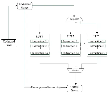
C. Decompression Engine
logic. The small LUT stores high-frequency instructions enabling them to be quickly decoded with a shorter codeword length. The BitMask unit executes the shifting of masks and XOR operations based on the instructions from the large LUT to obtain the original instructions. The BitMask unit also accesses the dictionary and executes shift operations in parallel during decompression. The proposed decompression engine has a decompression bandwidth of 32 bits/cycle.
Figure 12. Logic diagram of decompression engine
V.
DECOMPRESSION ENGINE IS USING
REVERSIBLE GATES
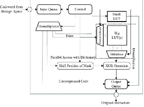
The reversible logic gates is used to design the Decompression Engine is shown in figure 13 consisted of a control unit, a demultiplexer, shift buffers, LUTs, and the BitMask unit. The control unit controls other units and assigns tasks to other units according to the control signals. The input queue initializes itself, collects compressed instructions from the storage space, and shifts the contents of the buffer after the decoding process is completed. The output queue stores the decompressed instructions and delivered them to the processor.
Figure 13: Block diagram of Decompression Engine by using reversible logic gates
VI.
RESULTS
Block diagram of Decompression engineRTL Schematic
COMPARISION TABLE:
Method AREA
(LUTS)
POWER (WATTS)
DELAY (NS)
EXISTING 107 0.162 2.668
PROPOSED 42 0.143 3.668
Simulation Results:
VII.
CONCLUSION
Embedded systems are constrained by the memory size. Code compression techniques address this problem by reducing the code size of the application programs. Dictionary-based code compression techniques are popular since they generate a good compression ratio by exploiting code repetitions. Recent techniques use bit toggle information to create matching patterns and thereby improve the compression ratio. However, due to lack of an efficient matching scheme, the existing techniques can match up to three bit differences. The proposed Reversible logic gates is used the design of a simple and fast decompression unit that is capable of decoding an instruction per cycle as well as performing parallel decompression Engine.
VIII.
REFERENCES
[1]. A. Wolfe and A. Chanin, "Executing compressed programs on an embedded RISC architecture," in Proc. 25th Annu. Int. Symp. Microarchitecture, pp. 81-91,Dec.1992.
[2]. C. Lefurgy, P. Bird, I.-C. Chen, and T. Mudge, "Improving code density using compression techniques," in Proc. 30th Annu. ACM/IEEE Int Symp. MICRO, pp. 194-203, Dec. 1997.
[3]. S.-W. Seong and P. Mishra, "A bitmask-based code compression technique for embedded systems," in Proc. IEEE/ACM ICCAD, pp. 251-254, Nov. 2006. [4]. S.-W. Seong and P. Mishra, "An efficient code
compression technique using application-aware bitmask and dictionary selection methods," in Proc. DATE, pp. 1-6 2007.
[5]. M. Thuresson and P. Stenstrom, "Evaluation of extended dictionarybased static code compression schemes," in Proc. 2nd Conf. Comput. Frontiers, pp. 77-86, 2005.
[6]. TMS320C62x DSP CPU and Instruction Set Reference Guide, Texas Instruments, Dallas, TX, USA, Jul. 2006.
[7]. H. Lekatsas and W. Wolf, "SAMC: A code compression algorithm for embedded processors," IEEE Trans. Computer-Aided Design Integr. Circuits Syst., vol. 18, no. 12, pp. 1689-1701, Dec. 1999. [8]. S. Y. Larin and T. M. Conte, "Compiler-driven cached
code compression schemes for embedded ILP processors," in Proc. 32nd Annu. Int. Symp. Microarchitecture, pp. 82-91, Nov. 1999.
[9]. Y. Xie, W. Wolf, and H. Lekatsas, "Code compression for VLIW processors using variable-to-fixed coding," in Proc. 15th ISSS,pp. 138-143, 2002.