CSEIT172380 | Received : 10 May 2017 | Accepted : 19 May 2017 | May-June-2017 [(2)3: 428-432]
International Journal of Scientific Research in Computer Science, Engineering and Information Technology © 2017 IJSRCSEIT | Volume 2 | Issue 3 | ISSN : 2456-3307
428
Password Based Door Locking System Using Microcontroller
Shaba Firdosh, Shikha, Prisha Kashyap, Bhavana Durgam, Nikhar Begum,
Shailendra Kumar Singh
Department of Electronics and Telecommunication, G D Rungta College of Engineering & Technology, Bhilai, Chhattisgarh, India
ABSTRACT
The purpose of this project is to provide security at (house, ATM, office etc.) in this system the user will have to register a unique password. The information will be stored in data base. Whenever the right password will be received, the controller will accordingly give instruction to dc motor. Dc motor will perform the action on door unlocking. We want to utilize the electronic technology to build an integrated and fully customized home security system at a reasonable cost.
Keywords : Motor, Microcontroller, LCD, Keypad, Buzzer
I.
INTRODUCTION
Many times we forgot to carry the key of our home. Or sometimes we come out of our home and door latch closes by mistake. In these cases it is really difficult to get inside the house. This project is designed to solve this purpose. Main concept behind this project is of a door-latch opening using a password entered through keypad. As well as turning on the Buzzer when password is entered wrong. Today people are facing more problems about security in all over world, nowadays security is the most essential issue everywhere in the world so security of everything gains higher and higher importance in recent years. The main component in the circuit is 8051 microcontroller. Here, 4*4 keypad is used to enter the password. The entered password is compared with the predefined password. If it is correct password, the system opens the door by rotating door motor and displays the status of door on LCD. If the password is wrong then door remains closed and displays ―password is wrong on LCD. It can be used at organizations to ensure authorized access to highly secured places. With a slight modification by replacing the motor driver with a relay driver, this circuit can be used to control the switching of loads through code. This circuit can be also modified by using EEPROM chip interfaced to the microcontroller and store the entered password in the
chip. Such an automatic lock system consists of electronic control assembly which controls the output load through a password. This output load can be a motor or a lamp or any other mechanical/electrical load.
II.
BLOCK DIAGRAM
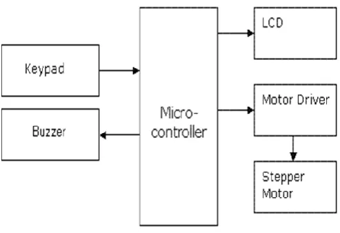
Figure 1: Block Diagram of password based door locking system
A. Microcontroller : This is the CPU (central processing unit) of our project. We are going to use a Microcontroller of 8051 family. The various functions of microcontroller are like:
Reading the digital input from Keypad.
Sending this data to LCD so that the person operating this project should read the password. Sensing the password using keypad and to check
wheather it is a correct password or a wrong password and rotate the stepper motor if the password entered is a correct password.
B. LCD : We are going to use 16x2 alphanumeric Liquid Crystal Display (LCD) which means it can display Alphabets along with numbers on 2 lines each are containing 16 characters.
Figure 2. LCD
C. BUZZER : We are going to use a buzzer to indicate the wrong password to open the door.
D. KEYPAD : User will enter the password using the keypad. In our project we are using 4*4 matrix to provide the input .
E. MOTOR DRIVER IC(L293D) : The Actuator's are those devices which actually gives the movement or to do a task like motor's. In the real world there are
various types of motors available which works on different voltages. So we need motor driver for running them through the controller. To get interface between motor and microcontroller [4]. We use L293D motor driver IC in our circuit. The Device is a monolithic integrated high volt- age, high current four channel driver designed to accept standard DTL or TTL logic levels and drive inductive loads (such as relays solenoids, DC and stepping motors) and switching power transistors. To simplify use as two bridges each pair of channels is equipped with an enable input. A separate supply input is provided for the logic, allowing operation at a lower voltage and internal clamp di- odes are included. This device is suitable for use in switching applications at frequencies up to 5 kHz[9]. The L293D is assembled in a 16 lead plastic package which has 4 centre pins connected together and used for heat sinking The L293DD is assembled in a 20 lead surface mount which has 8 centre pins connected together and used for heat sinking.
III.
METHODOLOGY
Electronic Code Lock System Circuit Design: Password Based Door Locking System design uses five major components – a Microcontroller, an L293D Motor Driver, a DC motor, a 4×4 matrix keypad and an LCD. Here AT89C52 Microcontroller is used and it is an 8-bit controller. This controller requires a supply voltage of +5V DC. In order to provide regulated 5V DC voltage to the controller we need to use 7805 power supply circuit. We can use 9V DC battery or 12V, 1A adaptor as a power source.
Reset Circuit Design: The reset pin of the microcontroller is kept active till the power supply is in the specified range and a minimum oscillation level is maintained. In other words to ensure the supply voltage does not falls below the threshold level of 1.2V and the reset pulse width is greater than 100ms (recommended for 89C51), we select the values of resistor and capacitor such that RC >=100ms. Here we select a 10K resistor and a 10uF electrolyte capacitor.
oscillator is connected between pin 18 and 19 of the microcontroller.
Compilation of Microcontroller Code: Once the circuit is designed and drawn on a piece of paper, the next step is to write and compile the code. Here we select the Kiel µVision software to write the program in C language. Prior to writing the code, general steps needs to be followed like creating a new project and selecting the target device or the required microcontroller. Once the code is written, we saved it with .c extension and then added it to the source file group under the target folder. The code is then compiled by pressing F7 key. Once the code is compiled, a hex file is created. In the next step, we use Proteus software to draw the circuit. The code is dumped into the microcontroller by right clicking on the IC and then adding the hex file.
Figure 3: Circuit Design In Proteus
A. Hardware Requirement :
1. 8051 Microcontroller (AT89S52) 2. Capacitor 10uf ,33pf
3. Pot 10k ohm
4. DC battery or 12V-1A Adaptor 5. Voltage regulator 7805
6. 16×2 LCD (on development board) 7. L293D Motor Driver board
8. DC gear motor
9. Indication –Led and buzzer 10. Hex keypad (microswitch) 11. Pullup resistor (sill)
B. Software Requirements: 1. Kiel compiler
2. Proteus 3. Flash Magic
C. Principle Behind The Circuit:
The main component in the circuit is 8051 microcontroller. Here, 4×3 keypad is used to enter the password. The entered password is compared with the predefined password. If it is correct password, the system opens the door by rotating door motor and displays the status of door on LCD.
If the password is wrong then door remains closed and displays ―pwd is wrong‖ on LCD Its design and working are very interesting and easy to implement. If you are interested to get detailed information about its design, working and applications, read the post Electronic Code Lock System using 8051 Microcontroller. Traditional lock systems using mechanical lock and key mechanism are being replaced by new advanced techniques of locking system. These techniques are an integration of mechanical and electronic devices and highly intelligent. One of the prominent features of these innovative lock systems is their simplicity and high efficiency.
D. Circuit Description
The total functioning of the―CODE LOCK SYSTEM is based on the software program which is burn inside the microcontroller IC 8051.The at89c51 IC is heart of the given circuitry because this IC is programmable 40pin dip IC in which we burn the program in rom. This IC has a 32 input lines through which we take the output pin no 9 is used for reset the microcontroller and make it in a initial condition pin no 31 is enable pin, it required low pulse for activating the microcontroller depends on the crystal connected to the xtal1 & xtal2. pin no 18&19 is used for providing the VCC of +5v pin 20 is grounded.
to the controller during the supply is turning on and off. The keypad used to give input signal is been interfaced with microcontroller are port0 (p0.1- p0.7).The controller fetches the hex code according to the instruction. The LCD is used for display device it is a 16 slots device usually used to show output status from the microcontroller . The output signal which be fetched by relay status followed by on/off status of electronic lock.
Figure 4: PCB Layout
IV.
RESULT AND SIMULATION
When it is entered a 4 digit password by the user it will display on LCD as ****.Therefore anyone else can’t see what the user enters. If it is the correct password, LCD displaying a
message ―Well come and the door will be opened. after 1minute time door is locked automatically.
If he is entered password incorrectly LCD displaying ―password error.
After opening the door if user wants to change his password, after pressing ―0 key and giving user id user can change his password.
If user wants to add more people to the system after opening the door pressing ―# key, user can add more users. System will give user id to each password.
Simulation of project is performed on PROTEUS and the code was written Kiel software. Code for the microcontroller to run DC motors IC (L293D) is written. In the simulation the relevant data to the Microcontroller is send through keypad. The Microcontroller processed the data and sent the information to the Actuator IC (L293D). The Actuator IC upon receiving information showed response by driving the DC motors.
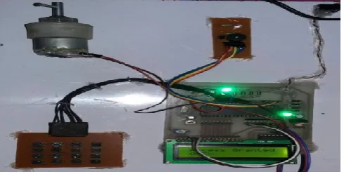
Here we are discussing the result in different cases as once when wrong password is entered the LCD displays “wrong password” entered and when correct password is entered the LCD shows the “access granted” and the motor rotates to open the door .
Case 1: when wrong password is entered the door doesn’t open.
Figure 5: Wrong Password Entered
Case 2: when correct password is entered the door get open.
Figure 6: Correct Password Entered
V.
CONCLUSION
VI.
FUTURE SCOPE
We can send this data to a remote location using mobile or internet.
We can add fingerprint sensor so entry will be allowed for the authorized person using their fingerprints.
We can add fire, wind and LPG sensors so that, the doors will automatically open.
VII.
REFERENCES
[1]. Technology Intelligent Home: SMS Based Home Security System with Immediate Feedback International Journal Of Advance Research In Science And Engineering http://www.ijarse.com IJARSE, Vol. No.2, Issue No.5, May, 2013 ISSN-2319-8354(E).
[2]. Liu, T., Guo, H., and Wang, Y., A new approach for color-based object recognition with fusion of color models‖, Congress on Image and Signal Processing Conference, Sanya-China, vol. 3, pp. 456-460, May 2008.
[3]. Wang, B., and Yuan, T., Traffic Police Gesture Recognition using Accelerometer‖, IEEE SENSORS Conference, Lecce-Italy,pp. 1080-1083, Oct. 2008.
[4]. Lalanne, T., and Lempereur, C., Color recognition with a camera: a supervised algorithm for classification‖, IEEE Southwest Symposium on Image Analysis and Interpretation, Tucson-Arizona, pp. 198-204, April 1998.
[5]. Signals, Systems and Computers, 2004 Conference Record of the Thirty-Eighth Asilomar Conference on Publication 7-Nov-2004 Volume: 1, on page(s): 577-581 Vol.1.
[6]. International Journal of Advanced Research in Computer Science and Software Engineering, Volume 2, Issue 10, October 2012.
[7]. International Journals of Biometric and Bioinformatics, Volume (3): Issue (1).
[8]. Mukesh Kumar Thakur, Ravi Shankar Kumar, Mohit Kumar, Raju Kumar Wireless Fingerprint Based Security System using Zigbee‖ , International Journal of Inventive Engineering and Sciences (IJIES) ISSN: 2319–9598, Volume-1, Issue-5, April 2013.
[9]. Mary Lourde R and Dushyant Khosla, Fingerprint Identification in Biometric Security Systems‖, International Journal of Computer and Electrical Engineering, Vol. 2, No. 5, October, 2010.
[10]. Song, M., Kim, B., Ryu, Y., Kim, Y., and Kim, S., A design of real time control robot system using android Smartphone‖ The 7th International Conference on Ubiquitous Robots and Ambient Intelligence (URAI), BusanKorea, Nov. 2010. [11]. Shilpa, V., Pradeep, H. S., and Kurian, M. Z.,
The Symbian Robot,‖ International Journal of Computer Science and Informatics (IJCSI), Vol-1, Issue-3.