National conference on Engineering Innovations and Solutions (NCEIS – 2018)
International Journal of Scientific Research in Computer Science, Engineering and Information Technology © 2018 IJSRCSEIT | Volume 4 | Issue 6 | ISSN : 2456-3307
CSEIT1846140 | Published – 08 May 2018 | May-June 2018 [ (4 ) 6 : 733-739 ]
733
Robotic Arm Manipulation Using Shape and Color Based On
Visual Servoing
Anusha G1,Ganavi D1,Revathi H1, Sahana P1, Mr. M V Sreenivas Rao2, Mr. Basavanna M2 1Student of Department of Electronics and Instrumentation, GSSSIETW, Mysuru, Karnataka, India
2Associate Professor of Department of Electronics and Instrumentation, GSSSIETW, Mysuru, Karnataka, India
ABSTRACT
The robot arm is an ongoing computer vision project for which many enhancements have been done during the last years; the aim of the paper is to present a system for controlling a robot arm, based on image processing and recognition. One of the common task performed in an industries are picking and placing of the object from one place to another place, hence the aim of our project is to pick and place the object by vision system. Vision system determines the random scattered object on the plane and picks the object by the gripper of the Robotic Arm and places it in a particular location. Without the vision system, it is difficult for the Robotic Arm to detect the colored object. The Arm Edge robot arm is made to pick and place the object based on color thresholding and shape analysis based on Principal Component analysis (PCA).
Keywords: Robot Arm, Pick And Place, PCA, Color And Shape
I.
INTRODUCTIONIn recent years, manipulation tasks for service robot have attracted many researches along the world to these topics. The manipulation is a hard problem that has been tackled in different ways. For example, in industry, the manipulation tasks are programmed by a human and only work in a structured environment. In the other hand, service robots use a different approach: compute positions a robotic arm using planning algorithms under unstructured environments where there is uncertainty, illumination conditions, errors on localization, cumulative errors, etc. This ways to solve the same problem, create the main difference between these two fields of robotics. In order to have a robust service robot, it must have the ability to grasp and manipulate different objects. To solve these tasks, it is required to have an accurate
II.
PROBLEM DEFNITION AND RESTRICTIONSWe need to calculate the center of mass representative of the end effector (gripper) of a manipulator arm of 7 degrees of freedom because this center is important to create a region of interest related to the gripper position and for visual servoing purposes it will be used for compute the error between one desired position to reach and the gripper position. The end effector has a specific color that is different from other objects in the scene. It is assumed that the position and color of the gripper in the real world is in the field of view of the camera. Once detected the gripper is necessary to calculate local features such as borders and points of interest that will be the basis for more complex calculations such as the homography between the camera and the end effector.
A. System Classification
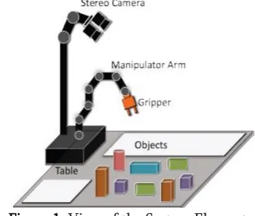
The system can be classified accordingly to [13]. The figure 1 shows the elements like camera, manipulator, objects and the table that is the common plane for vision and manipulator system. In this way, the system has a binocular stand-alone configuration. Is important to mention that the camera has the stereo function, but we only use the left camera.
Figure 1. View of the System Elements
III.
COLOR SEGMENTATIONA. Color Space
Before to the image processing is important to define the color space. One of the main problems in
dynamic environments is lighting conditions. In this sense, it is necessary to isolate or control the lighting. Theoretically, one of the color spaces that can control lighting of brightness is HSV (Hue Saturation and Value). In this case, the conversion from RGB to HSV is performed by the equations (1), (2) and (3) [14].
B. Pixel Classification
Segmentation is the process of divides the image into regions [14]. For doing this exist different techniques (based on thresholds, line detection, etc), but here we present a scheme inspired by the classification of pixels in an image given a specific color in HSV and using the Euclidean distance (4) as a measure for similarity.
The variables xi and yi define two points in the Euclidean Space so they are H and S parameters from HSV (without considering the Value component V, because is the brightness of the scene). As mentioned before, the problem of image segmentation can be presented as pixel classification, where the pixels are features in the Euclidean Space. In the literature [15], this problem has been solved by using unsupervised learning (KMeans). For the case of supervised learning, the KNN-like methods are used.
in Equation (5) and a set of pixels, if the Euclidean distance of the pixels to the Centriod is less than or equal to r, is considered that these pixels are in that color. A start criterion for assigning r is a visual inspection of the space of H and S values for a set of colors, considering that the end effector has a specific color. Section VI considers the value of this parameter.
color = (H,S)
In this implementation, only HSV is considered. For future work is desirable compare the performance of different color spaces.
IV.
CENTRIOD CALCULATIONThe first stage for compute the Centriod (centre of mass) of an object is the isolation of this object from others and then using the mean of the x,y positions forget the centre. These steps are discussed below.
A. Connected Components
Connectivity between pixels is a basis concept in digital image processing and allows defining limits and regions. Two pixels are connected if they have: common neighbors (using 4- or 8- neighbor test), similar intensity values, and if exists a path between them [16]. In [17] is considered the fact of a connected component in binary images has a topological structure. The regions inside of limits and its correspondence with limits is 1 to 1. This process it also allows know which components are in others.
This process can understand as labelling. Once the segmentation has been performed, the labelling of every isolated region is calculated. In this step we maintain only the larger area in the sense that this area is the more representative structure from gripper.
B. Using mean for Centriod calculation
Once that the connected components algorithm and the larger area is maintain, the next step is perform
the calculation for get the centre of using equation (6), where f(x,y) is binary image and x,y are the pixel positions.
V.
LOCAL FEATURESA. Corners
Corners or interest point’s detection is previous process for homography estimation. This process is only applied in the segmentation image (only on largest area of the segmented color on the end effector). One of the most popular methods for corner detection is the Harris Algorithm [18]. This technique implements invariance to any corner and its response will be positive in region with corners, negative unregions with borders and small in flat The feature tracking is other important issue related to homography estimation, because for getting good pose estimation the same points must be the same on every frame taken from the camera. This process internally uses a matching points calculation for getting similar points in every frame taken from camera.
VI. POSE ESTIMATION
A general procedure for estimate the homography between two images is described in [22]. The main stages are:
a) Compute the interest points in each image. b) Calculate a set of interest points matches based on proximity and similarity.
c) The homography is estimated using this matching.
However, we need to find the homography H between a set of points in image plane and a set of points in world frame, this relationship is given in equation (7).
Where x1, y1 are the coordinates related to the image frame IFr and x2, y2 are for the world frame WFr. In figure 2, we can see the largest area taken from the gripper (marked with a green rectangle).
Figure 2. The largest area of gripper is marked with a green rectangle.
VI.
IMPLEMENTATIONThe results reported in this document were performed using the OpenCV libraries [14] in python language running on a Linux (Ubuntu 8.04) platform on a PC Intel Centrino with 512 MB of RAM. We obtain only the left image from a stereo camera with a resolution of 320x240 pixels and the average image processing for each image was 0.05 seconds. Figure 3 shows the real system and we can see the camera, manipulator arm, end effector (gripper), the objects and the table (common plane for the system).
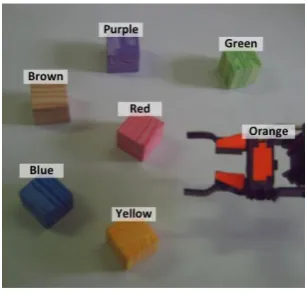
A. Color Set
The color set is shown in Figure 4 and is delimitated by the elements in the equation (8).
UT = yellow, blue, brown, {purple, red, green, orange}
In this set the end effector color is orange. This color can be changed but is important that has enough linear separability from other colors. We pick up 100 samples from every element of the color (using the mouse and the clicking in the object). For every color we get the mean (or color Centriod) using only HS components. Equation (9) shows this.
Where colori is the i-th representative color (or color mean), HkSk are the samples and n is the total of samples.
Figure 3. Real system and its elements
Figure 4. Colors Set
B. Segmentation and Local Features
noise that comes in the form of misclassified pixels or bad segmentation.
This noise increment as the radius r increases. We are not consider the V value because theoretically is the brightness of the scene, but depending on the hour of the day and lighting conditions is necessary adjust r to reject or accept more colors for better segmentation.
One way to not consider the noise for the calculus of the end effector Centriod is eliminate all small areas (areas that do not exceed a threshold) in the contour extraction step.
Figure 5: Centriod of object
The specific Centriod for end effector color is shown in equation 10.
Gripper _ color = (8,105)
Considering different values in r the noise increments. For example, in r=50 we can see in that some pixels related to yellow color are bad classified like orange pixels. For avoiding this bad calculus on feature extraction step, we only calculate features on the larger area segmented from the gripper. The corners calculation is performed in the binary image related to larger area and which has been filtered from noise.
VII.
RESULTSThe theoretical analysis and implementation results involve the detection and monitoring of the gripper
of a manipulator arm. This section demonstrates the application of these concepts using real time images based on shape and color.
This Performed using the Euclidean distance from the Centriod and maintain only the larger distance and finally apply this to the roi calculation, because the largest distance is related to get the circular mask.
The Figure 6 shows images related to:
Figure 6a shows the binary image after the segmentation.
Figure 6b shows how to dump the code to robot arm and to terminal the code.
Figure 6c shows the picking of the object based on color and shape.
Figure 6d shows the placing of the object to the particular location.
Figure 6(a). Binary Image
Figure 6(b). Terminal of code.
Figure 6(c). Picking of Object
Figure 6(d). Placing Of Object
object in the image and then a human selects a set of vertices that represents a specific form. These vertices are used to build a polygonal region of interest that filters out those pixels outside from the vertices and create a binary image.
VIII.
CONCLUSIONThis work presented a fast scheme for compute the tracking and feature extraction for an end effector of a manipulator arm. The current vision system is not susceptible to errors, for example, in cases when the gripper is too far from camera or there is bright light in the scene, the segmentation fails. After segmentation, the process continues to calculate the interest points in the gripper because these features are intrinsic properties of the gripper that will perform more complex calculations, such as the homography and determining a rotation of the gripper with respect to the camera. In future work, it is desirable to compare the detection process using a scheme based on pattern matching, object classification and even other color spaces in order to make it more robust to noise.
IX.
REFERENCES[1] E. Marchand and F. Chaumette. “Feature tracking for visual servoing purposes”. Advances in Robot Vision - From Domestic Environments to Medical Applications, Sept. 2014.
[2] L. Mejías, S. Saripalli, P. Campoy, and G. S. Sukhatme. “Visual servoing of an autonomous helicopter in urban areas using feature tracking”. Journal of Field Robotics, vol. 23, no. 3-4, pp. 185-199, 2016.
[3] M. Prats, P. Martinet, A. del Pobil, and S. Lee. “Robotic execution of everyday tasks by means of external vision/force control”. Intelligent Service Robotics, vol. 1, no. 3, pp. 253-266, Jul. 2017.
[4] Mebarki R., Krupa, A., Chaumette F. “Image moments-based ultrasound visual servoing”. Robotics and Automation, 2017, pp. 113 -119 .
[5] Junping Wang and Hyungsuck Cho. “Micropeg and Hole Alignment Using Image Moments Based Visual Servoing Method”. Transactions on Industrial Electronics, Vol. 55, No. 3, pp. 1286-1294, March 2008.
[6] Rajruangrabin and D. Popa. “Robot head motion control with an emphasis on realism of Neck-Eye coordination during object tracking”. Journal of Intelligent and Robotic Systems, pp. 1-28, Sep. 2016.
[7] Y. H. Liu and H. Wang. “Adaptive visual servoing of robot manipulators” in Advances in Robot Control: from Everyday Physics to Human-Like Movements, Springer, 2006, pp. 55-82.
[8] M. Maidi, J.-Y. Didier, F. Ababsa, and M. Mallem. “A performance study for camera pose estimation using visual marker based tracking”. Machine Vision and Applications, vol. 21, no. 3, pp. 365-376, Apr. 2015.
[9] Pomares, J., García, G. J., Payá, Torres, F. “Image Motion Estimator to Track Trajectories Specified With Respect to Moving Objects”. Informatics in Control Automation and Robotics, vol. 15, pp. 207-217. 2008.
[10] N. Greggio, A. Bernardino, C. Laschi, J. Santos-Victor, and P. Dario. “Real-Time 3D stereo tracking and localizing of spherical objects with the iCub robotic platform”. Journal of Intelligent & Robotic Systems, pp. 1-30, Feb. 2011.
[11] P. J. Sequeira Gonçalves, L. F. Mendonça, J. M. C. Sousa, and J. R. Caldas Pinto. “Uncalibrated Eye-to-Hand Visual Servoing Using Inverse Fuzzy Models”. IEEE Transactions on Fuzzy Systems, Vol. 16, No. 2, pp. 341-353, Apr. 2008. [12] Janabi-Sharifi, F.; Marey, M. “A Kalman-Filter-Based Method for Pose Estimation in Visual Servoing”. Robotics, IEEE Transactions on, vol.26, no.5, pp. 939-947, Oct. 2013.
Perception Laboratory, University of Stockholm, Sweden. 2012.
[14] OpenCV Reference Manual v2.2. Available online.línea:https://code.ros.org/trac/opencv/ex port/4761/trunk/opencv/doc/opencv.pdf.[June 2010].
[15] Tse-Wei Chen, Yi-Ling Chen, Shao-Yi Chien, “Fast image segmentation based on K-Means clustering with histograms in HSV color space”, In Multimedia Signal Processing, 2008 IEEE 10th Workshop on, pp.322-325, Oct. 2008.
[16] Rafael C. Gonzalez, Richard E. Woods. Digital Image Processing. Upper Saddle River, NJ. Prentice Hall. 2002.
[17] S. Suzuki and K. Abe. “Topological structural analysis of digitized binary images by border following”. Computer Vision, Graphics, and Image Processing, vol. 30, no. 1, pp. 32-46, Apr. 1985.
[18] C. Harris and M.J. Stephens. “A combined corner and edge detector”. Alvey Vision Conference, pp. 147–152, 1988.
[19] J. Shi and C. Tomasi, “Good features to track”. 9th IEEE Conference on Computer Vision and Pattern Recognition, pp. 593-600. June 1994.
[20] Gómez-Allende, Darío Maravall.
“Reconocimiento de Formas y Visión Artificia”l.
Wilmington, DE. Addison-Wesley
Iberoamericana. 1994.
[21] Faugeras, Oliver and Long Quang-Tuan. “The Geometry of Multiple Images”. Cambridge: MA. The MIT Press. 2001.
[22] Hartley Richard and Zisserman Andrew.