Enhanced FPGA Implementation of the Hummingbird
Cryptographic Algorithm
İsmail San1 and Nuray At1
1 Department of Electrical and Electronics Engineering, Anadolu University, Turkey
{isan, nat}@anadolu.edu.tr
Abstract. Hummingbird is a novel ultra-lightweight cryptographic algorithm aiming at resource-constrained devices. In this work, an enhanced hardware implementation of the Hummingbird cryptographic algorithm for low-cost Spartan-3 FPGA family is described. The enhancement is due to the introduction of the coprocessor approach. Note that all Virtex and Spartan FPGAs consist of many embedded memory blocks and this work explores the use of these functional blocks. The intrinsic serialism of the algorithm is exploited so that each step performs just one operation on the data. We compare our performance results with other reported FPGA implementations of the lightweight cryptographic algorithms. As far as author’s knowledge, this work presents the smallest and the most efficient FPGA implementation of the Hummingbird cryptographic algorithm.
Keywords: Lightweight cryptography, FPGA implementation, coprocessor approach.
1 Introduction
Low-cost smart devices like RFID tags and smart cards are rapidly becoming pervasive in our daily life. Well known applications include electronic passports, contactless payments, product tracking, access control and supply-chain management just to name a few. But the small programmable chips that passively respond to every reader have raised concerns among researchers about privacy and security breaches. A considerable body of research has been focused on providing RFID tags with cryptographic functionality, while scarce computational and storage capabilities of low-cost RFID tags make the problem challenging [1]. This emerging research area is usually referred to as lightweight cryptography which has to deal with the trade-off among security, cost, and performance [5].
The paper is outlined as follows: In Section 2, the Hummingbird encryption process is presented. In Section 3, the coprocessor approach to FPGA implementation of the Hummingbird cryptographic algorithm is introduced. Performance results and comparisons are given in Section 4. Finally, some conclusions are drawn in Section 5.
2 The Hummingbird Encryption
In this section, we present the encryption process for the Hummingbird cryptographic algorithm. Note that the information given in this section can be found in [2,3,6], they are included here simply for the sake of completeness.
Hummingbird is neither a block cipher nor a stream cipher, but a rotor machine equipped with novel rotor-stepping rules [6]. It has a hybrid structure of block cipher and stream cipher with 16-bit block size, 256-bit key size, and 80-bit internal state. A top-level description of the Hummingbird encryption is given in Figure 1 which consists of four 16-bit block ciphers and four 16-bit internal state registers RS1, RS2, RS3 and RS4, and a 16-stage Linear Feedback Shift Register (LFSR). PTi represents the i-th plaintext block and CTi represents the corresponding i -the ciphertext block. The 256-bit key K is divided into four 64-bit subkeys
and which are used in the four block ciphers, respectively. For further details, see [2,3,6].
3 Efficient FPGA Implementation
We use the coprocessor approach which takes advantage of the embedded memory blocks in FPGA to implement Hummingbird cryptographic algorithm. This approach reduces the area requirements in terms of slices since only the datapath and linear feedback shift register (LFSR) module are realized in slices. With this approach, efficiency (throughput/occupied slices) of the FPGA implementation of the Hummingbird cryptographic algorithm is increased considerably with respect to the previously reported FPGA implementations [6] of the algorithm, see Table 1.
3.1 FPGA Specifics
The Spartan-3 generation of FPGAs are specifically designed to meet the needs of high volume, cost-sensitive electronic applications [13]. They have a dedicated carry logic together with various arithmetic logic gates that support wide logic and arithmetic functions.
4
F-LUT
A[4:1] D F[4:1]
F1 F2
FAND
0 1
CY0F
0 1 1
CYSELF
CYMUXF
XORF F5MUX
FXMUX
FFX
D Q XQ
BX
CIN
X F5
BXOUT Bottom Portion
4
G-LUT
A[4:1] D F[4:1]
G1 G2
GAND
0 1
CY0G
0 1 1
CYSELG
CYMUXG
XORG FiMUX
GYMUX
FFY
D Q YQ
BY
Y Fi
BYOUT Top Portion
FXINB FXINA
COUT
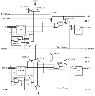
Figure 2 shows the architecture of a Spartan-3 slice [11]. A slice includes two 4-input Lookup Table (LUT) function generators (F-LUT and G-LUT), two storage elements (flip flops FFX and FFY), a carry logic (multiplexers CYSELF, CYMUXF, CYSELG, CYMUXG and gates FAND, GAND, XORF, and XORG) and two wide function multiplexers (F5MUX and FiMUX). Some slices also provide two 16x1 distributed RAM and two 16-bit shift registers as an additional blocks.
One of the primitives needed in the implementation of Hummingbird cryptographic algorithm is a modulo addition of two 16-bit numbers. A 2-bit summation can be
realized using one slice. Hence, 16-bit addition is implemented using eight slices. A 2-bit full-adder calculates the sum of two bits x and y on the same level and carry input (cin), if any transferred from a previous bit level, yielding
and carry out.
A dedicated carry logic transfers the carry bit through CYSELF, CY0F and CYMUXF multiplexers. F-LUT function generator produces . The output of F-LUT and cin bit is XORed by the XORF gate. This provides the sum. The sum result is then stored in FFX flip flop. Carry out bit is produced by CYMUXF multiplexer where x and cin are the inputs and the F-LUT output is used as a selection line.
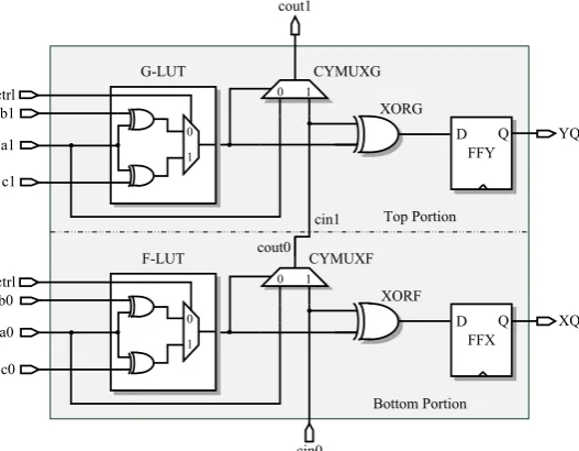
Figure 3 shows a 1-bit addition of three different input sources using primitives of a Spartan-3 slice. Here, one of the sources is connected to the carry chain logic immediately. The other one is selected using the control signal in the LUT function generator. The LUT provides the result of XOR operation of two input signals
or a depending on the control signal. Carry out bit is transferred to upper slices so that to extend the 1-bit addition to 16-bit addition. The flip-flops store the sum value.
0 1 CYMUXF
XORF
FFX
D Q XQ
cin0
Bottom Portion ctrl
0 1
F-LUT cout0
a0 b0
c0
0 1 CYMUXG
XORG
FFY
D Q YQ
cin1 Top Portion ctrl
0 1 G-LUT
cout1
a1 b1
c1
Other primitives needed in the implementation of Hummingbird cryptographic algorithm are realized in LUT function generators. There is no need to use arithmetic gates or carry chain logic provided in a slice. As mentioned before, one slice includes two LUTs and two storage elements and all stages operate on 16-bit data since the datapath is 16-bit wide. So, the required slice count for each stage is eight.
We emphasize the fact that all Virtex and Spartan FPGAs consist of many embedded memory blocks to store large amount of data compared to flip flops in the slices. They support various configuration options including RAM, ROM, FIFOs, large look-up tables, and shift registers as wells as various data widths and depths. We refer the reader [14] for further information. This work explores the use of these functional blocks, that is to say the coprocessor approach [4]. Specifically, the register file and instruction memory of coprocessor is implemented on such memory blocks yielding substantial reduction in the slice usage.
3.2 Overall Architecture
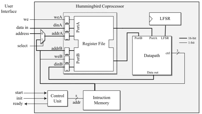
The overall architecture of the Hummingbird coprocessor is shown in Figure 4 which consists of a register file, datapath, LFSR module, instruction memory and control unit.
Register File
P
or
tA
addrA dinA weA
P
or
tB
addrB
weB Datapath
LFSR
PortA PortB LFSR
Data out
Intruction Memory dinB
ctrl 3 16-bit 1-bit 0
1 User
Interface
8 Control
Unit addr start
init ready
we
data in address
select
Hummingbird Coprocessor
Figure 4. Hummingbird coprocessor.
Hummingbird coprocessor performs a modulo addition, XOR, and S-box layer
efficiency. Instructions are first preloaded to the instruction memory. They are then fetched to control the datapath.
3.3 Register File, Instruction Memory, and Control Unit
The register file stores 16-bit plaintext, 256-bit secret key, four 16-bit internal state registers RS1, RS2, RS3 and RS4, and other necessary registers such as zero and temporary registers. The internal states and initial vector for LFSR are first determined by the initialization process. They are then updated after each encryption. Note that the same key is usually used for successive encryption of plaintext blocks. Thus, the coprocessor only needs to load plaintext blocks from input to the register file. This results in a very efficient input interface for the coprocessor.
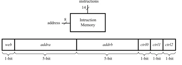
The instruction memory provides necessary control signals for the datapath. It also determines which register is used at each step. Write enable field for port B, web, is used to write the data to the register file from the datapath. The instruction memory is realized via an embedded memory block. Figure 5 shows the adapted instruction format. Since all instructions have the same format, 16-bit fixed instructions are fetched without the need for decoding. A single 1Kx18 block RAM would be sufficient to store necessary instructions for initialization and processes.
Intruction Memory
web addra addrb ctrl0 ctrl1 ctrl2
1-bit 5-bit 5-bit 1-bit 1-bit 1-bit
14
8 address
instructions
Figure 5. Instruction format
The control unit is actually formed by a program counter. When init signal is asserted, the program counter addresses the instruction memory so that the instructions for the initialization process are provided to the datapath. Similarly, if
start signal is asserted, the program counter addresses the encryption process instructions. After the completion of the encryption, the ready signal is set; hence, the user can access the ciphertext from the register file via user interface.
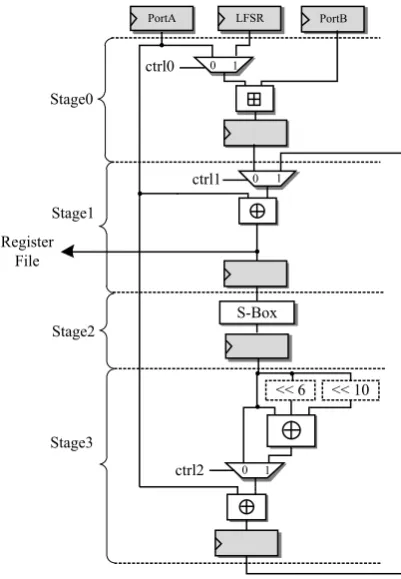
3.4 Datapath of the Coprocessor
transaction on the data. Intrinsic properties of the Spartan-3 device are utilized to complete a transaction with a minimal path delay.
The datapath consists of four functional units performing operations required by the Hummingbird cryptographic algorithm. These functional units are realized in four stages and the stages are connected via pipeline flip-flops. Each stage fits into eight slices. All stages except Stage 2 need control signals to determine the data flow path. The longest path in terms of logic and routing delay occurs in the addition of two 16-bit numbers due to the carry chain. Note that this is an unavoidable operation. To decrease the path delay in one stage, we minimize the use of consecutive logic components by introducing flip flops as pipeline registers.
1 0 ctrl0
1 0 ctrl1
S-Box
1 0 ctrl2
<< 10 << 6
PortA PortB
Stage0
Stage1
Stage2
Stage3
LFSR
Register File
Figure 6. Datapath of the Coprocessor for Hummingbird.
Stage 0 performs a modulo
2
16 addition on data provided by the register file orstage, Stage 3, performs the linear transformation on the incoming data. At this stage, the control signal is necessary to select whether the linear transformation is applied to the output of the substitution step in Stage 2. Note that the rotation of bits at the last stage does not need any component. This can be done only with appropriate wiring.
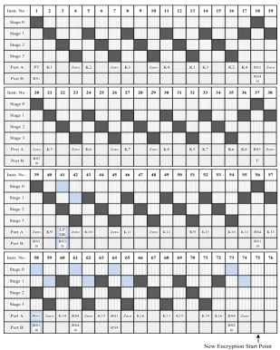
3.5 Scheduling of Instructions
Instruction level serialism is applied to the Hummingbird coprocessor in order to complete the encryption process with a minimum instruction count. Figure 7 shows the designed instruction scheduling of the encryption process where first row indicates the instruction number and the other rows indicates the active stage.
1
PT Instr. No :
Stage 0 Stage 1 Stage 2 Stage 3 Port A RS1 Port B 2 K1 3 4 Zero 5 K2 6 7 Zero 8 K3 9 10 Zero 11 K4 12 13 K1 14 K3 15 16 K2 17 K4 18 RS2 RS4 in 19 Zero 20 Zero Instr. No :
Stage 0 Stage 1 Stage 2 Stage 3 Port A RS2 in Port B 21 K5 22 23 Zero 24 K6 25 26 Zero 27 K7 28 29 Zero 30 K8 31 32 K5 33 K7 34 35 K6 36 K8 37 RS3 T 38 Zero 39 Zero Instr. No :
Stage 0 Stage 1 Stage 2 Stage 3 Port A RS3 in Port B 40 K9 41 LF SR RS3 in 42 Zero 43 K10 44 45 Zero 46 K11 47 48 Zero 49 K12 50 51 K9 52 K11 53 54 K10 55 K12 56 RS4 RS1 in 57 K13 58 RS1 Instr. No :
Stage 0 Stage 1 Stage 2 Stage 3 Port A RS1 in Port B 59 Zero 60 K14 61 RS4 RS4 in 62 Zero 63 K15 64 RS1 RS4 65 Zero 66 K16 67 68 K13 69 K15 70 71 K14 72 K16 73 RS4 RS2 in 74 Zero 75 76
New Encryption Start Point
Generally, each instruction performs an operation on the data. However, a small amount of instructions do not perform any operation on the data. They rather provide necessary data to the next stage. This is the case when loading the internal state from the register file. Loading from the register file impairs the performance of the overall system. Such instructions cause performance degradation since additional instructions are to be stored in the memory.
Our proposed datapath decreases the instruction count for the Hummingbird encryption in two ways. One is to manage the sequence of instructions so that every stage deals with an operation. The other one is to update the internal registers while other operations are being performed. Internal state updating is done via pipelined operation: appropriate instructions are selected to load the input data for the internal state registers without affecting the performed instruction at that time. Such pipelined instructions are colored with blue in Figure 7.
In general, each instruction activates only one stage performing one operation. However, a few instructions process two operations at a time. This happens when updating the internal states. Note that state updating can be done after the encryption process is completed. But, this would increase the total instruction count. Such operations can be combined with the other instructions. The use of inactive stages improves the overall system performance by reducing the instruction count.
The similar approach is used in the Hummingbird initialization process. We remark that the initialization takes 312 clock cycles where the encryption takes 75 clock cycles which includes the state updates.
4 Results and Comparisons
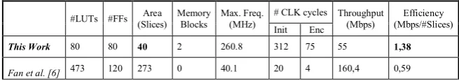
We implemented the Hummingbird coprocessor on Xilinx Spartan-3 device which is low cost FPGA by means of VHDL language. The hardware performance of the Hummingbird cryptographic algorithm is studied in [6] where the lightweight architecture is based on loop unrolling of the inner 16-bit block ciphers. That implementation realizes all operations of the block cipher in one cycle consuming resources notably. On the other hand, the proposed method in this work significantly reduces (273/40) the area in terms of the slice count by introducing coprocessor approach. Table 1 summarizes FPGA implementation results of the Hummingbird cryptographic algorithm in both studies.
Table 1. FPGA implementation results of the Hummingbird encryption.
#LUTs #FFs (Slices) Area Memory Blocks Max. Freq. (MHz) # CLK cycles Throughput (Mbps) (Mbps/#Slices) Efficiency Init Enc
This Work 80 80 40 2 260.8 312 75 55 1,38
Our proposed method requires lower area in terms of slices. Even though the throughput may seem lower than that of in [6], the overall efficiency is increased substantially (1.38/0.59).
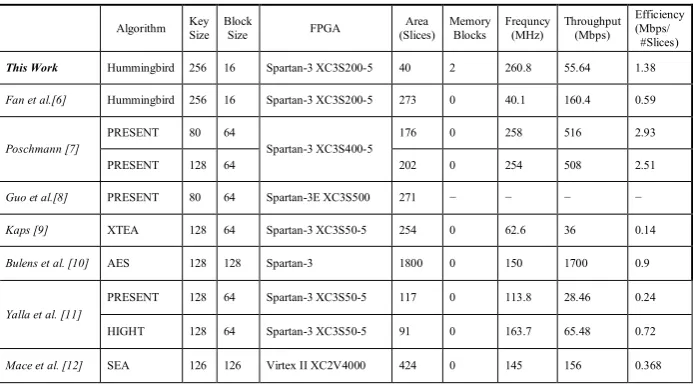
Table 2 is given in order to see where our proposed method stands among other FPGA implementations of lightweight cryptographic algorithms. As seen from the table, our work has the smallest area requirement among all and also provides well enough efficiency.
Table 2. Performance comparison of FPGA implementations of lightweight
cryptographic algorithms
Algorithm Key Size Block Size FPGA (Slices) Area Memory Blocks Frequncy (MHz) Throughput (Mbps) Efficiency (Mbps/ #Slices) This Work Hummingbird 256 16 Spartan-3 XC3S200-5 40 2 260.8 55.64 1.38
Fan et al.[6] Hummingbird 256 16 Spartan-3 XC3S200-5 273 0 40.1 160.4 0.59
Poschmann [7]
PRESENT 80 64
Spartan-3 XC3S400-5
176 0 258 516 2.93
PRESENT 128 64 202 0 254 508 2.51
Guo et al.[8] PRESENT 80 64 Spartan-3E XC3S500 271 − − − −
Kaps [9] XTEA 128 64 Spartan-3 XC3S50-5 254 0 62.6 36 0.14
Bulens et al. [10] AES 128 128 Spartan-3 1800 0 150 1700 0.9
Yalla et al. [11]
PRESENT 128 64 Spartan-3 XC3S50-5 117 0 113.8 28.46 0.24
HIGHT 128 64 Spartan-3 XC3S50-5 91 0 163.7 65.48 0.72
Mace et al. [12] SEA 126 126 Virtex II XC2V4000 424 0 145 156 0.368
5 Conclusions
As far as author’s knowledge, this work presents the smallest and the most efficient FPGA implementation of the ultra-lightweight cryptographic algorithm Hummingbird thanks to the coprocessor approach. The coprocessor approach is enabled due to the fact that FPGAs have dedicated memory blocks. The algorithm is serialized so that each step performs just one operation on the data. The datapath of the Hummingbird coprocessor is implemented in four stages and the instruction count is reduced via pipelining technique.
References
1. J. Lee and Y. Yeom, “Efficient RFID authentication protocols based on pseudorandom sequence generators”, Des. Codes Cryptogr. 51:195–210, 2009
2. X. Fan, “Efficient Cryptographic Algorithms and Protocols for Mobile Ad Hoc Networks” Ph.D thesis, Department of Electrical and Computer Engineering, University of Waterloo, 2010.
3. D. Engels, X. Fan, G. Gong, H. Hu, and E. M. Smith, “Hummingbird: Ultra-Lightweight Cryptography for Resource-Constrained Devices”, to appear in the proceedings of the 14th International Conference on Financial Cryptography and Data Security - FC 2010, 2010. 4. J.-L. Beuchat, E. Okamoto, and T. Yamazaki, “Compact implementations of BLAKE-32 and
BLAKE-64 on FPGA,” 2010, cryptology ePrint Archive, Report 2010/173.
5. Thomas Eisenbarth, Sandeep Kumar, Christof Paar, Axel Poschmann and Leif Uhsadel, A Survey of Lightweight-Cryptography Implementations, IEEE Design & Test of Computers, vol. 24, no. 6, November 2007, pp. 522-533.
6. X. Fan, G. Gong, K. Lauffenburger, and T. Hicks, “FPGA Implementations of the Hummingbird Cryptographic Algorithm”, IEEE International Symposium on Hardware-Oriented Security and Trust (HOST), 2010.
7. A. Poschmann, “Lightweight Cryptography - Cryptographic Engineering for a Pervasive World”, Ph.D. Thesis, Department of Electrical Engineering and Information Sciences, Ruhr-Universit¨ aet Bochum, Bochum, Germany, 2009.
8. X. Guo, Z. Chen, and P. Schaumont, “Energy and Performance Evaluation of an FPGA-Based SoC Platform with AES and PRESENT Coprocessors”, Embedded Computer Systems: Architectures, Modeling, and Simulation - SAMOS’2008, LNCS 5114, pp. 106-115, 2008.
9. J.-P. Kaps, “Chai-tea, cryptographic hardware implementations of xTEA,” in INDOCRYPT 2008, ser. LNCS, D. Chowdhury, V. Rijmen, and A. Das, Eds., vol. 5365. Springer, Dec 2008, pp. 363–375.
10. P. Bulens, F.-X. Standaert, J.-J. Quisquater, and P. Pellegrin, “Implementation of the AES-128 on Virtex-5 FPGAs”, Progress in Cryptology AFRICACRYPT 2008, LNCS 5023, pp. 16-26, 2008.
11. Panasayya Yalla and Jens-Peter Kaps, “Lightweight Cryptography for FPGAs”, International Conference on ReConFigurable Computing and FPGAs ReConFig'09, 2009. 12. Mace F, Standaert FX, Quisquater JJ (2007). FPGA implementation(s) of a Scalable
Encryption Algorithm, IEEE Trans. Very Large Scale Integ. (VLSI) Syst. 16(2): 212-216.
13. Xilinx Inc, Spartan-3 Generation FPGA User Guide, August, 2010. Available online at: http://www.xilinx.com/support/documentation/user_guides/ug331.pdf
![Figure 1. Hummingbird encryption [2]](https://thumb-us.123doks.com/thumbv2/123dok_us/1869784.1243263/2.595.226.379.407.668/figure-hummingbird-encryption.webp)