A Diagonal Fault Attack on the Advanced
Encryption Standard
Dhiman Saha? Debdeep Mukhopadhyay?? Dipanwita RoyChowdhury? ? ?
Keywords:Fault Attack, AES-Rijndael, Clock Glitching
Abstract. The present paper develops an attack on the AES algorithm, exploiting multiple byte faults in the state matrix. The work shows that inducing a random fault anywhere in one of the four diagonals of the state matrix at the input of the eighth round of the cipher leads to the deduction of the entire AES key. We also propose a more generalized fault attack which works if the fault induction does not stay confined to one diagonal. To the best of our knowledge, we present for the first time actual chip results for a fault attack on an iterative AES hardware running on a Xilinx FPGA platform. We show that when the fault stays within a diagonal, the AES key can be deduced with a brute force complexity of approximately 232
, which was successfully performed in about400seconds on an Intel Xeon Server with 8 cores. We show further that even if the fault induction corrupts two or three diagonals,2and4faulty ciphertexts are necessary to uniquely identify the correct key.
1
Introduction
Fault tolerance in cryptography is nowadays a widely researched topic. The advent of mobile handsets, smart cards, personal digital assistants (PDAs) with crypto-graphic hardware requires protection against accidental or intentional faults. The first use of faults to attack crypto-hardware dates back to 1996 by Boneh, De-Millo and Lipton [1, 2] from Bellcore. Since then fault based attacks have been extended successfully to both asymmetric and symmetric ciphers. The concept of Differential Fault Analysis (DFA) was introduced by Biham et. al. [3] on the Data Encryption Standard (DES). The Advanced Encryption Standard (AES), being the global standard for sensitive data encryption, has been a popular target for fault attacks. With the work on optical fault induction reported in [4], research in the field of fault-based side channel cryptanalysis of AES has gained considerable attention. Less costly methods for fault injection include variation of supply volt-ages, clock frequency, clock glitches or temperature variations. Several differential fault attacks on AES have been reported in literature. While most attacks exploit the properties of the encryption function, recent reported attacks have also tar-geted the key scheduling. In [5], authors mount DFA on AES by inducing faults atbytelevel to the input of ninth round of AES using 250 faulty ciphertexts. The
?
Dhiman Saha is a PhD Student in the Department of Computer Sc. and Engg, IIT Kharagpur, India. E-mail: [email protected]
??
Debdeep Mukhopadhyay is an Assistant Professor in the Department of Computer Sc. and Engg, IIT Kharagpur. E-mail: [email protected].
? ? ?
attack reported in [6] recovers the key with around 128 to 256 faulty ciphertexts. In [7], Dusart et. al. show that using abytelevel fault induction anywhere between the eighth round MixColumn and ninth round MixColumn, the attacker is able to break the key with 40 faulty ciphertexts. The authors of [8] mounted an attack on AES with just singlebytefaults using two faulty outputs. The point of induction was at the input of the eighth or ninth round. In [9], the authors present a fault attack on AES when the fault is induced in a 32 bit word of AES in the ninth round. The authors propose two models for fault occurrence. In the first model, they assume that at least one of the bytes among the four targetted bytes are uncorrupted. While in the second model they assume that all the four bytes are corrupted. The former fault requires 6 faulty ciphertexts, while the later requires around 1500 faulty ciphertexts to discover the key. We observe that when the as-sumptions are on the value of a byte (either it being faulty or uncorrupted) the number of faulty pairs is quite small. We claim that attacks based on multiple byte faults are more practical as opposed to those based on single byte faults. Also as induction of faults requires high precision instruments (more the precision, more the cost!) and are harder to guarantee, an attack which requires large number of faulty pairs is impractical. Among the attacks on key expansion, it has been sug-gested in [10, 11] that with bytelevel fault, a minimum of two faulty ciphertexts and a brute force search of 48 and 40 bits respectively reveal the AES key. In [12] a fault attack against AES was proposed, which revealed the key using a single byte fault induction at the input of the eighth round. The attack exploited the inter-relations between the fault values in the state matrix after the ninth round MixColumn operation. Through simulations it was shown that the attack reduced the AES-128 key space to 232using a single faulty ciphertext.
However in spite of several research works, there is surprisingly no reported work on actual fault attacks on real life hardware. Most of the attacks proposed, model the fault as a non-zero disturbance of a single byte of the AES state matrix. In this paper we introduce a new fault attack on AES, based on the fault induction in the diagonals of the AES state matrix at the input of the eighth round. Our attack named as the Diagonal Fault Attack is thus based on a multi-byte level fault modeling as opposed to a single byte level fault model. We have verified the entire attack on an iterative architecture of AES on a Xilinx FPGA platform with real-time fault injection using clock glitching via less sophisticated and less costly instruments. We show that when a non-zero fault is induced in one of the four diagonals of the AES state matrix at the input of the eighth round, a single faulty ciphertext is needed to reduce the key space of AES-128 to 232. The
brute force search requires around 400 seconds on an eight core Intel Xeon server running Linux operating system. Further, we present attack methods to retrieve the key when the faults are not confined to one diagonal. We show that when two diagonals are corrupted the attacker needs two faulty ciphertexts, whereas if three diagonals are disturbed four ciphertexts are required to ascertain the correct key. Our experimental findings show that when the eighth round of AES is clocked at slightly higher than the maximum permissible frequency, in all the faulty cases at most three of the four diagonals are disturbed, and hence can be cryptanalyzed by the proposed method.
fault models.Section 8reports the experimental results, and the comparisions are furnished insection 9. The working principle of the Finally, the work is concluded in section 10.
2
The Description of AES-Rijndael Algorithm
The description of the AES-Rijndael algorithm may be found in [13]. The typical round is described in the current subsection. The 128 bit message and key sizes have been considered, but the discussion can be extended to other specifications of the Rijndael block cipher.
The 128 bit input block to AES is arranged as a 4×4 array of bytes, known as the state matrix, refer tofigure 1. The elements of the matrix are represented by the variable,bij, where 0≤i, j≤3 andi, jrefers to the row and column positions.
b
00
b
b
b
b
b
b
b
b
b
b
b
b
b
b
b
10
20
30
01
02
03
11
12
13
21
22
23
31
32
33
Fig. 1.The State Matrix of AES-Rijndael
The algorithm has ten rounds and the keys of each round are generated by a key scheduling algorithm. The design of the key scheduling algorithm of AES is such that the knowledge regarding any round key reveals the original input key (named as the master key) from which the round keys are derived. The input state matrix (plaintext) is transformed by the various round transforms. The state matrix evolves as it passes through the various steps of the cipher and finally emerges in the form of ciphertext.
The rounds of AES use the following steps (figure 2):
1. The Byte Sub Step: The Byte Sub is the only non-linear step of the cipher. It is a bricklayer permutation consisting of an S-box applied to the bytes of the state. Each byte of the state matrix is replaced by its multiplicative inverse, followed by an affine mapping. Thus the input bytexis related to the output
y of the S-Box by the relation,y =A.x−1+B, where A and B are constant
matrices[13].
2. The ShiftRows Step: Each row of the state matrix is rotated by a certain number of byte positions. This is a byte transposition step.
3. The MixColumn Step: The MixColumn is a bricklayer permutation operating on the state column by column. Each column of the state matrix is considered as a 4-dimensional vector where each element belongs toGF(28). A 4×4 matrix
vector. This operation is applied on all the 4 columns of the state matrix [13]. HereM is defined as follows:
M =
2 3 1 1
1 2 3 1
1 1 2 3
3 1 1 2
4. AddRoundKey: Each byte of the array is exclusive-ored with a byte from a corresponding array of round subkeys.
The first 9 rounds of AES-Rijndael are identical - only the last round is not because the MixColumn step does not exist.
ADD ROUND KEY
SHIFT ROW
ADD ROUND KEY ROUND 1
BYTE SUB
MIX COLUMN
−9
ADD ROUND KEY
BYTE SUB
SHIFT ROW ROUND 10
Fig. 2.The Round Transforms of AES-Rijndael
The proposed fault attack is based on a fault model which assumes fault in-duction in the diagonals of the AES state matrix. Hence before proceeding to the attack we give a formal definition of the diagonal of the state matrix.
Definition 1. Diagonal: A diagonal is a set of four bytes of the state matrix, where theith diagonal is defined as follows:
Di={bj,(j+i)mod4 ; 0≤j <4} (1)
According to the above definition and with reference to the state matrix of AES (refer figure 2) we obtain the following four diagonals.
D0= (b00, b11, b22, b33)
D1= (b01, b12, b23, b30)
D2= (b02, b13, b20, b31)
D3= (b03, b10, b21, b32)
3
Fault Model of the Attack
The Fault model determines the assumptions that we make about the nature of the fault that are induced in the attack. The implementation of AES we target is an iterative one. Research shows that unrolled or pipelined design of AES are unpopular because they do not allow to operate the cipher in Output Feedback Mode (OFB) or Cipher Block Chaining (CBC) mode, which are more secured modes of operation.
The attacker aims to inject a fault at the input of the eighth round. An iterative design helps in this regard, as the attacker is able to control the timing of fault induction by simply counting the number of clock edges from the start of an encryption. We classify the induced faults into four models:
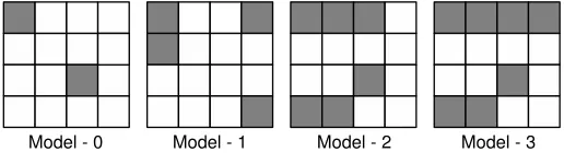
Model 0 (M0):A random non-zero fault is induced in one of the diagonals,
D0, D1, D2 andD3.
Model 1 (M1):A random non-zero fault occurs at most across two diagonals. Model 2 (M2):A random non-zero fault occurs at most across three diago-nals.
Model 3 (M3):A random non-zero fault occurs at most across all four diag-onals.
Fig. 3. Fault Models
Figure 3 shows example faulty states according to the above models. It may be noted in the figure, that in the first state matrix only diagonalD0 is affected.
In the second state matrix both D0 and D3 is corrupted. The diagonals D0, D2
andD3 are disturbed in the third state matrix, whereas all the four diagonals are
affected in the fourth state matrix. Thus the faults in the four state matrices are respectively in accordance with models, 0, 1, 2 and 3.
It may be noted that all the models are multi-byte fault models and thus attacks based on these models are more feasible than those based on single byte faults as found in the literature. Among the models,M0⊆M1⊆M2⊆M3. Thus in the series,M0, M1, M2, M3, the higher fault models are more relaxed and thus attacks based on them are more realistic. For example, most ideal fault model would have beenM3 which captures all possible faults. We show in our proposed attack methods, that faults based on M0, M1 and M2 lead to the successful retrieval of the key. However, the same attack is not possible for faults according to M3 but not belonging to M2. It may be noted from the above facts that the proposed attack can capture all faults upto three bytes, as three bytes can never lie across all the four diagonals.
4
The Attack Environment
In this section we outline the target design of AES which has been attacked by the proposed fault attack. Subsequently, we present the fault injection technique adopted for experimentally carrying out the proposed attack.
4.1 Target Implementation of AES
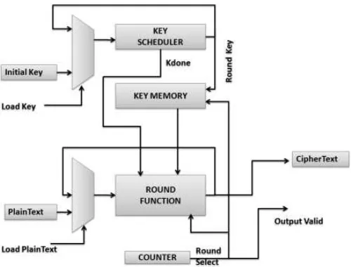
We have implemented an iterative architecture of AES using Verilog HDL. The implementation is exhibited infigure 4. The key and plaintext get loaded when the ‘Load Key’ and ‘Load Plaintext’ signals are asserted. The module first generates each round-key and stores it in the Key Memory. Once key generation is over theKey Scheduler asserts theKdone signal. This happens once for each new key loaded. Then the round function module iterates10 times before generating the ciphertext which is indicated by theOutput validsignal. The controller consists of a counter which keeps track of the number of rounds and also selects the specific round key from theKey Memory. The design is downloaded on a Xilinx Spartan-3E XC3S500E platform and operates at a maximum frequency of 36 MHz.
Fig. 4. Implementation of AES
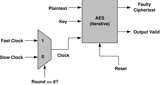
4.2 Fault Injection Set-up
the beginning of the eight round. The clocks are generated from an Agilent 33250A 80Mhz Function/Arbitrary Waveform Generator. So only the eighth round will run on the faster clock. The frequency of the faster clock has to be carefully adjusted from a signal generator. It should be slightly higher than the maximum frequency that the AES design supports. Our experiments show that there is a relation between the number of faults induced and the frequency of the faster clock. We have verified using Xilinx ChipScope Pro embedded logic analyzer that the number of faulty diagonals is directly proportional to the clock frequency.
Fig. 5. Fault Injection Set-up
In the next section, we present fault attacks on AES according to the fault modelM0. Hence we have non-zero faults in one of the four diagonals of the AES state matrix at the input of the eighth round.
5
The Proposed Attack according to Fault Model
M
0
We first show that faults which are confined to one diagonal are equivalent and can be used to retrieve the key using the same method.
5.1 Equivalence of faults in the same diagonal
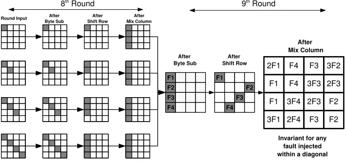
Lets us first observe the propagation of a fault injected in diagonal D0 through
the round transformations from the input of the eighth round to the output of the ninth round.Figure 6 shows the diffusion of a byte fault induced at the input of the eighth round. The difference of the state matrices of the two ciphers are depicted in the figure.
A
1 A2 A3 A4 A
5 A6 A7 A8 A
9 A
10A11A12 A
13A14A15A16 A
1 A
2 A3 A4 A
6 A7 A8 A5 A 10 A 9 A 11 A 12 A
13A14A15 A 16 1 F F 4 F 2 F 3 Round Shift Row Eighth F 3 F 3 F 1 1 2F F 1 3 F 4 F 4 F 1 3F 4
4 F 2 F2 F 3 2 F 3 2 F 3 3 2F2
F2 F 1 F 4 F 3 F2 2f’ f’ f’ 3f’ Round Mix Column Eighth Round Byte Sub f’ f Eighth
Ninth Round Byte Sub
Tenth Round Byte Sub
Tenth Round Shift Row Ninth Round Mix Column
Ninth Round Shift Row f’
Fig. 6.Propagation of Fault Induced in the input of eighth round of AES
the ninth round MixColumn (as depicted infigure 6) will still hold.Figure 7shows some cases of fault induction in diagonalD0. The faults vary in the number of bytes
that are faulty inD0 at the input of the eight round. We emphasize on the fact
irrespective of the number or positions of bytes that are faulty inD0, the fault is
confined to the first columnC0of the state matrix at the end of the eighth round.
So the fault propagation in the ninth round for all these cases is similar and leads to the same byte inter-relations at the end of the ninth round.
Fig. 7. Equivalence of different kinds of faults induced in diagonal D0 at the input of
eighth round of AES
In the last paragraph, we saw that any fault inD0results inC0getting affected.
the input of the eighth round in theithdiagonal, 0≤i≤3, leads to theithcolumn being affected at end of the round. There are four diagonals and faults in each diagonal maps to four different byte inter-relations at the end of the ninth round. These relations are depicted infigure 8. These relations will remain unchanged for any combination of faults injected within a particular diagonal. Each of the four sets of relations infigure 8will be used to form key dependent equations. The next subsection explains the generations of the equations from the byte inter-relations.
Fig. 8.Byte inter-relations at the end of ninth round corresponding to different diagonals being faulty
5.2 Equation generation from byte inter-relations
Our attack requires an attacker to obtain a single faulty ciphertext and one fault-free ciphertext. Let the fault-fault-free ciphertext be denoted by CT while the faulty one be denoted byCT0 Let, the two ciphertexts be represented by:
CT=
x1 x2 x3 x4
x5 x6 x7 x8
x9 x10x11x12
x13x14x15x16
and
CT0=
x1+A1 x2+A2 x3+A3 x4+A4
x5+A6 x6+A7 x7+A8 x8+A5
x9+A11 x10+A12 x11+A9 x12+A10
x13+A16x14+A13x15+A14x16+A15
The corresponding key matrix for the tenth round is:
K10=
K00K01K02K03
K10K11K12K13
K20K21K22K23
K30K31K32K33
,where each termkij (0≤i, j≤3) is also a byte value.
Let us assume that the fault was injected somewhere in diagonalD0. So the
inter-relations after the ninth round MixColumn corresponding to D0 given in
figure 8are to be considered. Combining the above facts we obtain the following set of equations to evaluate the values of the key bytes K00, K13,K22 and K31,
thus revealing 32 bits of the AES key.
ISB(x1+K00) +ISB(x1+A1+K00) = 2[ISB(x8+K13) +ISB(x8+A5+K13)]
ISB(x8+K13) +ISB(x8+A5+K13) =ISB(x11+K22) +ISB(x11+A9+K22)
ISB(x14+K31) +ISB(x14+A13+K31) = 3[ISB(x8+K13) +ISB(x8+A5+K13)]
The unknowns in the above set of equations is the value of the key bytesK00,
K13,K22 andK31.
The attacker obtains reduced solution spaces for the bytesK00,K13,K22 and
K31 from the three equations. At first he guesses all values of K00 and K13 in
the first equation and filters out all such key pairs that do not satisfy it. He now has a reduced key space for K13 which he uses for the second equation and for
each such guess he guesses all values for K22 and proceeds similarly. The worst
case complexity for one pass of the algorithm is 216 and is independent of the
value of the fault induced. The above system of equations is used to reduce the possibilities of 32 bits of the key. The average size of the reduced key space per 32 bits is roughly 28.
We briefly state the three other system of equations as follows:
In order to obtain (K01, K10, K23, K32) the attacker uses the following
equa-tions:
ISB(x15+K32) +ISB(x15+A14+K32) = 2[ISB(x2+K01) +ISB(x2+A2+K01)]
ISB(x2+K01) +ISB(x2+A2+K01) = [ISB(x5+K10) +ISB(x5+A6+K10)]
ISB(x12+K23) +ISB(x12+A10+K23) = 3[ISB(x2+K01) +ISB(x2+A2+K01)]
In order to obtain (K02, K11, K20, K33) the attacker uses the following
equa-tions:
ISB(x9+K20) +ISB(x9+A11+K20) = 2[ISB(x3+K02) +ISB(x3+A3+K02)]
ISB(x3+K02) +ISB(x3+A3+K02) = [ISB(x16+K33) +ISB(x16+A15+K33)]
In order to obtain (K03, K12, K21, K30) the attacker uses the following
equa-tions:
ISB(x7+K12) +ISB(x7+A8+K12) = 2[ISB(x10+K21) +ISB(x10+A12+K21)]
ISB(x10+K21) +ISB(x10+A12+K21) = [ISB(x13+K30) +ISB(x13+A16+K30)]
ISB(x4+K03) +ISB(x4+A4+K03) = 3[ISB(x10+K21) +ISB(x10+A12+K21)]
Using all the equations above we get a total key space of 232. We get different
sets of equations corresponding to a different diagonal being affected. So we will have four equation-sets each covering all possible faults within a specific diagonal. In the analysis above we assumed that the faulty diagonal was known to the attacker. This can be easily extended to a scenario where the fault location is not known to the attacker. In such a case the attacker guesses the faulty diagonal and repeats the attack four times. So the size of the key space will be 232×4 = 234
which can be brute forced feasibly with present day computational power. In the previous section, we have considered the scenario when the fault is restricted to one of the diagonals of the AES state matrix. In the next two sections, we describe attack methods when the fault spreads among the diagonals. First, we present the attack technique when at most two diagonals are affected by the fault induction.
6
The Proposed Attack according to Fault Model
M
1
In this section the fault induction takes place in the AES state matrix during the beginning of the eighth round according to fault model M1. Thus, at most two diagonals may get affected by the fault. It may be noted that since the fault model
M0 is a special case of M1, the attack strategy for M1 also works if the fault is induced according toM0, that is if only one diagonal gets affected. Hence the attack based on model M1 is more general than that based on modelM0.
6.1 Propagation of Faults when two diagonals are affected
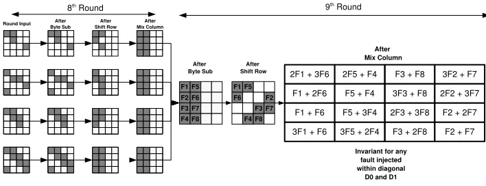
Infigure 9, we observe the propagation of faults when the diagonals, D0 and D1
are affected.
The fault is induced at the input of the eighth round. We note that for all possible faults in these two diagonals, the nature of faults in the state matrix at the input of the ninth round MixColumn is an invariant. This property is exploited to develop equations which are used to retrieve the correct key.
6.2 The equations based on the fault propagation
Fromfigure 9, we note that for all possible faults corrupting the diagonalsD0 and
D1, the nature of the faults at the input of the ninth round MixColumn is an
invariant and as depicted in the figure. Hence, the fault nature at the output of the ninth round MixColumn is also an invariant. We denote the fault values in the first column of the output of the ninth round MixColumn bya0, a1, a2, a3, where
Fig. 9.Fault Propagation if diagonalsD0 areD1 are affected
The following equations thus hold (referfigure 9):
a0= 2F1+ 3F6
a1=F1+ 2F6
a2=F1+F6
a3= 3F1+F6
Here it may be noted that the additions and multiplications are in GF(28),
with the reduction polynomial same as that in AES. Eliminating, F1 and F6 we
obtain:
a1+a3=a0
2a1+ 3a3= 7a2
We can expressa0, a1, a2, a3 in terms of the fault free ciphertext (CT), faulty
ciphertext (CT0) and the tenth round key (K10) defined insection5.2, as follows:
a0=ISB(x1+K00) +ISB(x1+A1+K00)
a1=ISB(x8+K13) +ISB(x8+A5+K13)
a2=ISB(x11+K22) +ISB(x11+A9+K22)
a3=ISB(x14+K31) +ISB(x14+A13+K31)
Thus if we use the inter-relationships among the bytesa0
is (0≤i≤3), and the above equations, we are able to reduce the possible key space ofK00, K13, K22, K31.
Similar to the solving mentioned insection 5.2, we know all the variables on the right hand side of the above equation from CT and CT0. We guess the bytes
K00, K13, K22, K31, and maintain a list of probable keys which satisfy the
inter-relationships among the bytesa0, a1, a2 anda3. We observe that using one faulty
ciphertext, the attacker reduces the key space ofK00, K13, K22, K31from 232to 216.
the two pairs leaves an unique key with a probability of 0.99. For few other cases, using two faulty ciphertexts leave two or three keys. If a third faulty ciphertext is obtained, then the exact key is identified.
Proceeding similarly equations are derived for all other columns at the output of the ninth round MixColumn. For example the second column involves the key bytesK01, K10, K23, K32. The equations corresponding to the third column yields
the key bytes K02, K11, K20, K33. Similarly, the fourth column leads to the key
bytesK03, K12, K21, K30.
Depending on the combination of two diagonals affected out of the four diag-onals, there are six such sets of equations. Hence if the attacker does not know which two diagonals are affected, he guesses the faulty diagonals and applies the corresponding set of equations to ascertain the key. Thus with two faulty cipher-texts the attacker reduces the AES key space to six possible keys, which he can easily brute force.
In the next section, we present an attack strategy if the fault gets spread to atmost three diagonals. This fault model,M2 thus covers the first two models of fault.
7
The Proposed Attack according to Fault Model
M
2
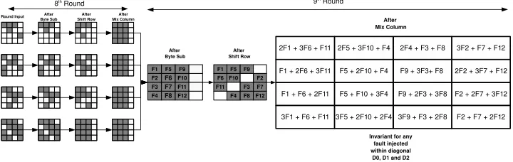
Infigure 10, we observe the propagation of faults when the diagonals,D0,D1 and
D2are affected.
Fig. 10.Fault Propagation if diagonalsD0,D1 andD2 are affected
Fromfigure 10, we note that for all possible faults corrupting the diagonalsD0,
D1andD2, the nature of the faults at the input of the ninth round MixColumn is
an invariant. The fault nature at the output of the ninth round MixColumn is as seen in the figure, also an invariant. We denote the fault values in the first column of the output of the ninth round MixColumn bya0, a1, a2, a3, where eachai is a byte 0≤i≤3.
The following equations thus hold (referfigure 9):
a0= 2F1+ 3F6+F11
a2=F1+F6+ 2F11
a3= 3F1+F6+F11
Here also the additions and multiplications are inGF(28), with the reduction
polynomial same as that in AES. Eliminating, F1,F6andF11 we obtain:
11a0+ 13a1= 9a2+ 14a3
As before in case of faults modeled byM1, we can expressa0, a1, a2, a3in terms
of the fault free ciphertext (CT), faulty ciphertext (CT0) and the tenth round key (K10) defined insection5.2, as follows:
a0=ISB(x1+K00) +ISB(x1+A1+K00)
a1=ISB(x8+K13) +ISB(x8+A5+K13)
a2=ISB(x11+K22) +ISB(x11+A9+K22)
a3=ISB(x14+K31) +ISB(x14+A13+K31)
Thus if we use the inter-relationship among the bytesa0
is (0≤i≤3), and the above equations, we are able to reduce the possible key space ofK00, K13, K22, K31.
Similar to the solving mentioned insection 5.2, we know all the variables on the right hand side of the above equation from CT and CT0. We guess the bytes
K00, K13, K22, K31, and maintain a list of probable keys which satisfy the
inter-relationship among the bytes a0, a1, a2 and a3. We observe that using one faulty
ciphertext, the attacker reduces the key space of K00, K13, K22, K31 from 232 to
224. However with four faulty ciphertexts, an intersection of the solutions obtained
from the two pairs leaves an unique key.
It may be noted that when the faults occur according to the modelM3, that is all the four diagonals are affected, the proposed method fails to obtain the key. However, as we show in the next section, when we clock the design at a slightly higher frequency than the maximum permissible frequency the faults occur according to the modelsM0, M1 and M2 with a much larger probability.
8
Experimental Results
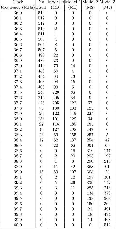
when the eighth round starts. The number of attempts to inject a fault at each step is 512. This is the maximum possible number of samples that Chipscope 7.1 can handle.
Table 1.Fault classification with clock frequency
Clock No Model 0 Model 1 Model 2 Model 3 Frequency (MHz) Fault (M0) (M1) (M2) (M3)
36.0 512 0 0 0 0
36.1 512 0 0 0 0
36.2 512 0 0 0 0
36.3 510 2 0 0 0
36.4 511 1 0 0 0
36.5 508 4 0 0 0
36.6 504 8 0 0 0
36.7 507 5 0 0 0
36.8 490 22 0 0 0
36.9 489 23 0 0 0
37.0 419 79 14 0 0
37.1 448 60 4 0 0
37.2 434 64 13 1 0
37.3 403 94 15 0 0
37.4 408 99 5 0 0
37.5 248 226 38 0 0
37.6 214 205 84 9 0
37.7 128 205 122 57 0
37.8 76 180 133 123 0
37.9 20 122 145 225 0
38.0 158 191 129 34 0
38.1 27 116 185 185 0
38.2 40 127 198 147 0
38.3 26 69 155 257 5
38.4 17 62 137 254 42
38.5 0 20 68 361 63
38.6 0 0 16 319 177
38.7 0 2 20 293 197
38.8 0 1 8 290 213
38.9 0 11 42 368 91
39.0 15 59 107 308 23
39.1 0 2 12 197 301
39.2 0 5 26 339 142
39.3 0 3 11 285 213
39.4 0 0 0 134 378
39.5 0 0 6 138 368
39.6 0 0 0 150 362
39.7 0 0 0 21 491
39.8 0 0 0 18 494
39.9 0 0 0 14 498
We note that at 36.3 MHz faults start to appear for the first time. Till 37.5 MHz faults under modelM0 dominate. From 38.1 to 38.4 MHz the faults under the model M0, M1 and M2 occur simultaneously with similar frequency.M2 starts to dominate when the clock frequency reaches 38.5 MHz and continues to do so till 39.4 MHz; during this periodM0 andM1 faults get reduced. After this from 39.5 MHz M3 faults start to dominate, whileM2 still appears but M0 and M1 faults vanish.
So, we observe that if the clock changes are confined between 36 to 37.4 MHz, then M0 faults occur primarily and in few cases M1 faults. Since as we have previously shown, the fault attacks based on the model M0 is the strongest and most powerful, we can indeed break the AES key using a single fault injection in 400 seconds (refersection 5).
9
Comparison with Existing Works and Experimental
Results
There have been considerable number of works on the subject. To the best of our knowledge, no reported works present fault attacks on real life implementations. In our paper, we have not only shown our attack on an FPGA implementation of AES but also demonstrated that fault injection via clock glitching can be a dangerous tool to the adversary.
In our approach, we have developed our attack based on multi-byte fault mod-els, compared to single byte fault models existing in literature except [9]. In [9], the authors use an attack based on four byte faults where he needs about 1500 faulty ciphertexts. However they do not outline any practical method through which such a large number of faulty ciphertexts can be obtained.
Finallytable 2compares the existing fault based attacks on AES with our work. The results show that though our work is based on multi-byte fault modeling, still it is able to attack AES with least number of faulty ciphertexts.
10
Conclusions
A new fault attack on AES based on multiple byte faults has been presented. Three attack strategies have been developed exploiting the disturbance in the diagonals of the AES state matrix at the input of the eighth round. The fault has been injected by the simple mechanism of clock glitching. For the first time in existing literature, the fault attack has been shown on actual hardware implementation. The experiments confirm that the fault attack outperforms existing works with respect to practical fault modeling and number of faulty ciphertexts needed.
References
1. D. Boneh, R.A. DeMillo and R.J. Lipton, “On the Importance of checking crypto-graphic Protocols for Faults,” inEurocrypt 1997. 1997, LNCS 1233.
2. D. Boneh, R.A. DeMillo and R.J. Lipton, “On the Importance of Eliminating Errors in Cryptographic Computations,” Journal of Cryptology, pp. 101–120, 2001. 3. E. Biham and A. Shamir, “Differential Fault Analysis of Secret Key Cryptosystems,”
Table 2. Comparison of Existing Fault Attacks on AES exploiting properties of the encryption function
Reference Fault Model Fault Location No. of
Faulty Encryptions
[6] Force 1 bit to 0 Chosen 128
[6] Implementation Dependent Chosen 256
[10, 11] Disturb 1 byte Key Scheduling 7
[5] i) Switch 1 bit i) Any bit of chosen bytes i)≈50 ii) Disturb 1 byte ii) Anywhere among 4 bytes ii)≈250
[7] Disturb 1 byte Anywhere between ≈40
last two MixColumns
[8] Disturb 1 byte Anywhere between 7th 2
round and 8thround MixColumn [12] Disturb 1 byte Anywhere between 7th 2
round MixColumn and 8thround MixColumn [9] 4 bytes:
i)One byte undisturbed Input of i) 6
ii)All 4 bytes disturbed ninth Round ii) 1500 This paper Multibytes:
i) M0 Anywhere between 7th i) 1
ii) M1 round MixColumn ii) 2
iii) M2 and 8thround MixColumn iii) 4
4. S. Skorobogatov and R. Anderson, “Optical Fault Induction Attacks,” in CHES 2002. 2002, LNCS 2523.
5. C. Giraud, “DFA on AES,” Cryptology ePrint Archive, Report 2003/008, 2003. 6. J. Blomer and J. P. Seifert, “Fault Based Cryptanalysis of the Advanced Encryption
Standard (AES),” inFC 2003. 2003, pp. 162–181, LNCS 2742.
7. P. Dusart, G. Letourneux and O. Vivolo, “Differential Fault Analysis on A.E.S.,” http://eprint.iacr.org/2003/010.
8. G. Piret and J. J. Quisquater, “A Differential Fault Attack Technique against SPN Structures, with Application to the AES and Khazad,” in CHES 2003. 2003, pp. 77–88, LNCS 2779.
9. M. Salmasizadeh A. Moradi, T. M. Shalmani, “A generalized method of differential fault attack against aes cryptosystem.,” inCHES, 2006, pp. 91–100.
10. J.Takahashi, T.Fukunaga and K.Yamakoshi, “DFA mechanism on the AES sched-ule,” inProceedings of4th
International Workshop on Fault Detection and Tolerance in Cryptography, FDTC, 2007, pp. 62–72.
11. J.Takahashi, T.Fukunaga, “Differential Fault Analysis on the AES Key Schedule,” http://eprint.iacr.org/2007/480, 2007.
12. Debdeep Mukhopadhyay, “An improved fault based attack of the advanced encryp-tion standard,” inAFRICACRYPT, 2009, pp. 421–434.