Available online: http://edupediapublications.org/journals/index.php/IJR/ P a g e | 516
Structural Analysis and Optimization of Inlet Manifold Used In 4
Stroke Engine
Kunnur Vijaya Kumar1 C Lakshmaiah2 Venkata Ramudu3
1,2,3 Branch: Machine Design
1P.G. Scholar, 2M.Tech Asst Professor, 3Head Of Department 1,2,3Geethanjali College Of Engineering &Technology
Email: - 1[email protected], 2[email protected]
ABSTRACT:
Fuelling framework is one of the pivotal factors that must be centered around, with the end goal to accomplish great eco-friendliness and low motor out outflows. Fuel infusion framework appears an encouraging technology as a medium to supply stifled fuel on account of its high fuel conveyance effectiveness, upgraded mileage and lessened motor out emanation. Delta manifolds majorly affect motor's exhibitions and emanation poisons. In car building, a bay complex or admission complex is the piece of a motor that provisions the fuel/air blend to the barrels. The essential capacity of the admission complex is to equitably circulate the burning blend to every admission port in the chamber head. At the season of conveyance the weight (0.0142MPa) connected inside in the bay complex. Indeed, even conveyance is vital to streamline the productivity and execution of the motor. Locally, normal admission manifolds are typically made of aluminum composites.
In this project 3D model of a channel complex utilized in the 4-stroke IC motor will be produced. At that point it is utilized to analysis the delta complex for limited component analysis. In this project, to check the deflections and stress esteems because of the gaseous tension load connected inside in delta complex amid the appropriation of air in barrels. Static analysis will be done to confirm the
deflections and stress esteems because of vibrations created in bay complex. In this examination NX_CAD software will be utilized for 3Dmodeling of channel complex, ANSYS software will be utilized for the limited component analysis of a gulf complex will be performed utilizing ANSYS software.
INTRODUCTION INLET MANIFOLD
In automotive designing, a gulf complex or admission complex is the piece of a motor that provisions the fuel/air blend to the chambers. The admission complex is Aluminum, steel or plastic cover that sits over the motor. It is joined to the highest point of the motor by an admission complex gasket that is made of plastic and elastic. The admission complex coordinates the air-fuel blend in the motor to the relating barrel where it is scorched to deliver power. The coolant courses through the admission complex to the barrel heads to decrease motor temperature. Extension, constriction, and warmth from the motor reason the gasket to come up short. This will cause coolant going through the admission complex to spill. A flawed complex gasket can likewise result in air being sucked through the cracked gasket, bringing about a vacuum hole and poor motor execution.
Available online: http://edupediapublications.org/journals/index.php/IJR/ P a g e | 517
from a solitary bay to the different barrels. Ordinarily, air will enter through a solitary gap and experience a throttle valve plate that can open and near control the amount of air that goes in. On a carbureted or throttle-body-infused motor, the fuel goes in just before the throttle plate, so the plate passes both air and fuel. After the valve, the air and in some cases fuel goes into a focal holding chamber called the "plenum," which goes about as sort of a supply.
A progression of cylinders or directs in the complex convey the air-fuel blend from the plenum load to the individual chambers; these are the "complex sprinters." Carbureted motors require straight sprinters, in light of the fact that the fuel beads noticeable all around don't care to circumvent corners. The length, inside breadth, volume and state of the sprinters are totally basic as far as power yield, and where in the rpm extend the motor makes that power.Air pressure going into the motor through the sprinters bounces back off the head's admission valves when they close like a spring. The pressure waves shoot back up as far as possible of the sprinter, and return; every one of these bounce cycles is known as a "harmonic." If you open the admission valve at simply the correct time, you can get the pressure wave in transit back down; the pressure waves pushes air through the valve, much like a supercharger.
Be that as it may, this supercharging impact just works in a specific rpm run, and the pressure waves can bounce back and forward a few times previously the valve opens once more. The length of the sprinter decides to what extent the harmonic takes to return to the admission valve. Hence, long sprinters will "supercharge" the motor at low rpm, and short sprinters will do it at high rpm. The tallness, width and volume of the sprinter decide how much air can
experience, which directs top-end horsepower.
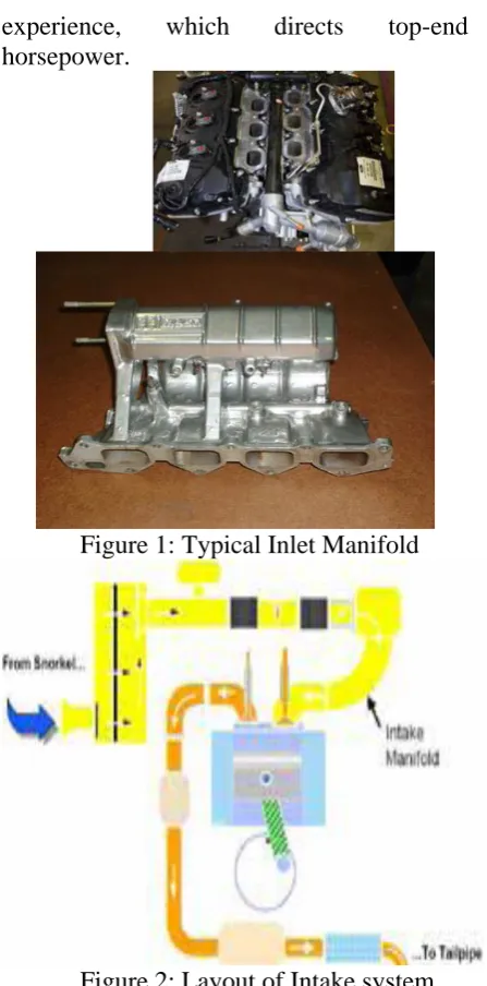
Figure 1: Typical Inlet Manifold
Figure 2: Layout of Intake system Each auto part is specifically in charge of alternate segments in a vehicle. Without the admission complex, which is the road through which the motor blend goes along, inner ignition isn't conceivable.
MATERIALS:
Available online: http://edupediapublications.org/journals/index.php/IJR/ P a g e | 518
in around 70% of present day vehicles the admission complex are currently produced using extraordinary warmth safe polymers and plastics.
Manifolds utilizing this sort of development help complex part weight by up to half and add to higher eco-friendliness. These admission manifolds are ordinarily formed from a glass fiber strengthened review of crystalline polymer that comprises of a mix an ofsyndiotactic polystyrene and polyamide. The polyamide nylon based materials give a decent answer for these segments as a result of their mechanical properties and their simplicity of processing amid their fabricate.
This sort of material is in a perfect world suited for supplanting metal in the engine applications in view of its quality, firmness, and concoction opposition under high temperature working conditions.
FUNCTIONS:
The air consumption complex guarantees the ideal filling of the motor barrels with an appropriate mass of carburant comprising of natural air and re-flowed debilitate gases. The admission complex likewise completes the capacity of coordinating other motor supply control capacities: fuel supply, fuel against dissipation framework control, and motor task point control. Henceforth, the air admission complex can likewise complete the capacity of motor supply mechatronic module, with the accompanying focal points: conservative size, cost, and gathering on the motor.
The admission complex essentially comprises of a volume of thermoplastic material with high warm and mechanical opposition, snared to the motor by methods for properly measured conductors and made in infusion forming technology and welding
of vibrating parts. The specialized arrangements fulfill needs as far as weight decrease and recyclable materials.
Admission manifolds outfitted with electronic control frameworks of air and gas liquid elements went for amplifying exhibitions, diminishing fuel utilization and CO2 and lessening the clamor produced by the motor. Indeed, even appropriation is a key capacity of the admission complex to expand the productivity and the correct execution of the motor.
APPLICATIONS:
The consumption complex has a few rounded branches and conveys air as well as air/fuel blend from the carburettor to the channel valves in the barrel head.
In carbureted motors, the admission complex conveys the air-fuel blend into the motor.
The cross-sectional territory of each cylinder should be kept little to keep up the high air/fuel speeds that enhance power age. In the meantime, it can't be too little, since that confines the wind stream to the motor at higher rates.
Electronic fuel infused motors with throttle body infusion additionally have consumption manifolds that convey air-fuel blend. With multi-point infusion, the admission manifolds convey air just and the cross-sectional zone of the cylinders can be bigger. More air can stream and the motor can deliver more power. Fuel is infused into the admission ports of the chamber head.
Available online: http://edupediapublications.org/journals/index.php/IJR/ P a g e | 519
That implies the admission complex is on one side and the ventilation system is on the other.
The design and introduction of the admission complex is a main consideration in the volumetric proficiency of a motor.
On numerous vehicles, the admission complex has a mounting for the carburetor and a rib that jolts onto the chamber head. It has a branch for every barrel to convey air-fuel blend into the ignition chamber.
Many admission manifolds have a water coat under the carburetor mounting. Hot coolant from the cooling framework courses through the water-coat and warms the complex. Warming is required in a carbureted motor to give better vaporization of the air-fuel blend.
Fuel-infused motor manifolds regularly have a plenum chamber that gives a repository of air and averts obstruction with the stream of air between individual branches. It additionally goes about as a silencer.
A diesel motor admission complex conveys air just, not fuel. What's more, since no fuel is vaporized in the complex, it isn't warmed.
Some diesels utilize a pneumatic or air-worked representative with a butterfly valve at the passage to the bay complex. This butterfly valve is just used to work the representative. It's anything but a throttle butterfly valve as observed on gas motors.
TYPES OF INLET MANIFOLD:
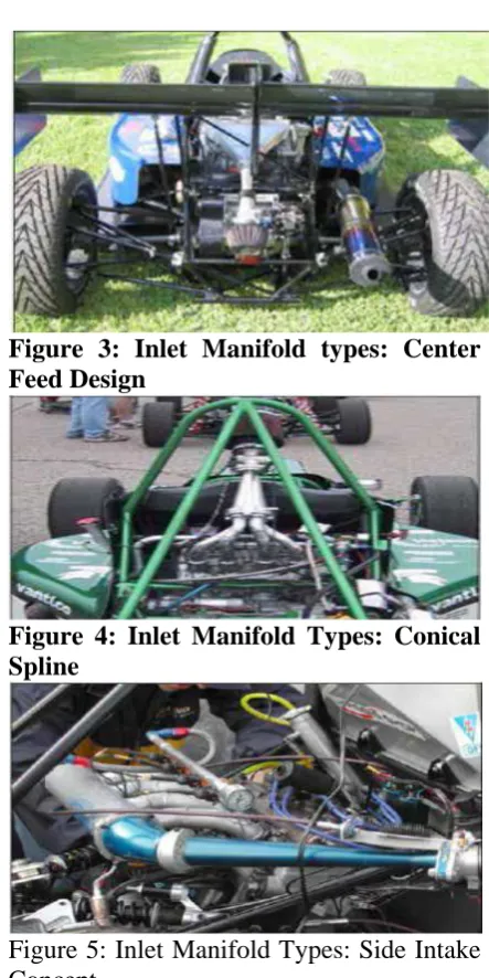
Figure 3: Inlet Manifold types: Center Feed Design
Figure 4: Inlet Manifold Types: Conical Spline
Figure 5: Inlet Manifold Types: Side Intake Concept
EFFECTS:
1) TURBULENCE:
Available online: http://edupediapublications.org/journals/index.php/IJR/ P a g e | 520
atomization. Better atomization takes into consideration a more total consume of all the fuel and lessens motor thump by growing the fire front. To accomplish this disturbance it is a typical practice to leave the surfaces of the admission and admission ports in the barrel head unpleasant and unpolished.
Just a specific level of disturbance is helpful in the admission. When the fuel is adequately atomized extra choppiness causes unneeded pressure drops and a drop in motor execution.
2) VOLUMETRIC EFFICIENCY:
The design and introduction of the admission complex is a main consideration in the volumetric productivity of a motor. Unexpected form changes incite pressure drops, bringing about less air (and additionally fuel) entering the burning chamber; superior manifolds have smooth shapes and steady advances between adjoining fragments.
Present day admission manifolds for the most part utilize sprinters, singular cylinders stretching out to every admission port on the barrel head which exude from a focal volume or "plenum" underneath the carburetor. The reason for the sprinter is to exploit the Helmholtz resonance property of air. Wind streams at significant speed through the open valve. At the point when the valve shuts, the air that has not yet entered the valve still has a considerable measure of force and packs against the valve, making a pocket of high pressure. This high-pressure air starts to adjust with lower-pressure air in the complex. Because of the air's dormancy, the evening out will in general waver: At first the air in the sprinter will be at a lower pressure than the complex. The air in the complex at that point endeavors to even out back into the
sprinter, and the swaying rehashes. This process happens at the speed of sound, and in many manifolds goes all over the sprinter ordinarily before the valve opens once more.
The littler the cross-sectional region of the sprinter, the higher the pressure changes on resonance for a given wind current. This part of Helmholtz resonance repeats one consequence of the Venturi impact. At the point when the cylinder quickens downwards, the pressure at the yield of the admission sprinter is diminished. This low pressure beat hurries to the info end, where it is changed over into an over-pressure beat. This heartbeat goes back through the sprinter and rams air through the valve. The valve at that point closes.
To saddle the full power of the Helmholtz resonance impact, the opening of the admission valve must be planned effectively, generally the beat could have a negative impact. This represents an extremely troublesome issue for motors, since valve timing is dynamic and dependent on motor speed, while the beat timing is static and subject to the length of the admission sprinter and the speed of sound. The conventional arrangement has been to tune the length of the admission sprinter for a particular motor speed where most extreme execution is wanted. Be that as it may, present day technology has offered ascend to various arrangements including electronically controlled valve timing.
Available online: http://edupediapublications.org/journals/index.php/IJR/ P a g e | 521
valve opening time can be so adjusted as to accomplish more prominent clearing of the barrel. The ventilation systems accomplish a vacuum in the barrel just before the cylinder achieves top perfectly focused. The opening bay valve can then at run of the mill pressure proportions fill 10% of the chamber before starting descending travel. Rather than accomplishing higher pressure in the barrel, the delta valve can remain open after the cylinder achieves base right on target while the air still streams in.
In a few motors the admission sprinters are straight for negligible opposition. In many motors, in any case, the sprinters have curves… and some exceptionally tangled to accomplish wanted sprinter length. These turns consider a more minimal complex, with denser bundling of the entire motor, thus. Additionally, these "wound" sprinters are required for some variable length/part sprinter designs, and enable the extent of the plenum to be diminished. In a motor with somewhere around six barrels the arrived at the midpoint of admission stream is about consistent and the plenum volume can be littler. To abstain from standing waves inside the plenum it is made as minimal as could reasonably be expected. The admission sprinters each utilization a littler piece of the plenum surface than the gulf, which supplies air to the plenum, for aerodynamic reasons. Every sprinter is put to have almost a similar separation to the primary delta. Sprinters, whose chambers fire close after one another, are not set as neighbors.
"180-degree consumption manifolds". Initially designed for carburetor V8 motors, the two planes, part plenum admission complex isolates the admission beats which the complex encounters by 180 degrees in the terminating request. This limits obstruction of one chamber's pressure waves with those of another, giving better torque
from smooth mid-extend stream. Such manifolds may have been initially designed for either two-or four-barrel carburetors, however now are utilized with both throttle-body and multi-point fuel infusion.
"Warmth Riser" now old, prior manifolds with 'wet sprinters' for carbureted motors utilized fumes gas redirection through the admission complex to give vaporizing heat. The amount of fumes gas stream preoccupation was controlled by a warmth riser valve in the ventilation system, and utilized a bi-metallic spring which changed pressure as indicated by the warmth in the complex. The present fuel-infused motors don't require such gadgets.
3) VARIABLE-LENGTH INTAKE MANIFOLD (VLIM):
Available online: http://edupediapublications.org/journals/index.php/IJR/ P a g e | 522
motor speed by methods for sliding valves into it when speed is lessened.
As the name suggests, VLIM can differ the length of the admission tract with the end goal to upgrade power and torque, and additionally give better eco-friendliness.
There are two principle impacts of variable admission geometry:
• Venturi impact – At low rpm, the speed of the wind current is expanded by coordinating the air through a path with restricted capacity (cross-sectional territory). The bigger path opens when the heap increments with the goal that a more prominent amount of air can enter the chamber. In double overhead cam (DOHC) designs, the air paths are often associated with independent valves so the shorter path can be rejected by deactivating the admission valve itself.
• Pressurization – A tuned admission path can have a light pressurizing impact like a low-pressure supercharger because of Helmholtz resonance. In any case, this impact happens just over a limited motor speed run which is straightforwardly affected by admission length. A variable admission can make at least two pressurized "problem areas." When the admission velocity is higher, the dynamic pressure pushing the air (as well as blend) inside the motor is expanded. The dynamic pressure is relative to the square of the bay velocity, so by making the entry smaller or longer the speed/dynamic pressure is expanded.
Many automobile makers utilize comparative technology with various names. Another normal term for this technology is Variable Resonance Induction System (VRIS).
UNIGRAPHICS INTRODUCTION
Overview of Solid Modeling
The Unigraphics NX Modeling application gives a strong modeling system to empower fast calculated design. Specialists can fuse their prerequisites and design confinements by characterizing scientific connections between various parts of the design.
Design specialists can rapidly perform reasonable and itemized designs utilizing the Modeling highlight and requirement based strong modeler. They can make and alter perplexing, reasonable, strong models intelligently, and with far less exertion than more customary wire casing and strong based systems. Highlight Based strong modeling and altering capacities enable designers to change and refresh strong bodies by straightforwardly altering the dimensions of a strong component as well as by utilizing other geometric altering and development methods.
Focal points of Solid Modeling
Strong Modeling raises the dimension of articulation with the goal that designs can be characterized as far as building highlights, instead of lower-level CAD geometry. Highlights are parametrically characterized for dimension-driven altering dependent on size and position.
Highlights
• Powerful implicit building focused shape highlights spaces, openings, cushions, managers, pockets-catch design purpose and increment efficiency
• Patterns of highlight occurrences rectangular and round clusters with relocation of individual highlights; all highlights in the pattern are related with the ace element
Available online: http://edupediapublications.org/journals/index.php/IJR/ P a g e | 523
• zero range
• Ability to chamfer any edge
• Cliff-edge mixes for designs that can't oblige finish mix sweep yet at the same time require mixes
Propelled Modeling Operations
• Profiles can be cleared, expelled or spun to frame solids
• Extremely powerful empty body direction transforms solids into thin-walled designs in a moment or two; internal divider topology will contrast from the external divider, if essential
• Fixed and variable range mixes may cover encompassing appearances and stretch out to a Tapering for modeling produced close net shape parts
• User-characterized highlights for basic design components (Unigraphics NX/User-Defined Features is required to characterize them ahead of time.
General Operation
Begin with a Sketch
Utilize the Sketcher to freehand a portray, and dimension a "layout" of Curves. You would then be able to clear the portray utilizing Extruded Body or Revolved Body to make a strong or sheet body. You can later refine the draw to accurately speak to the question of enthusiasm by altering the dimensions and by making connections between geometric items. Altering a dimension of the draw adjusts the geometry of the portray, as well as the body made from the outline.
Making and Editing Features
Highlight Modeling gives you a chance to make highlights, for example, openings, spaces and scores on a model. You can then straightforwardly alter the dimensions of the component and find the element by dimensions. For instance, a Hole is characterized by its distance across and length. You can straightforwardly alter these parameters by entering new qualities. You can make strong assortments of any coveted design that can later be characterized as a frame highlight utilizing User Defined Features. This gives you a chance to make your own custom library of frame highlights.
• Associativity
Cooperatively is a term that is utilized to demonstrate geometric connections between individual bits of a model. These connections are set up as the designer utilizes different capacities for model creation. In an acquainted model, imperatives and connections are caught automatically as the model is produced. For instance, in an affiliated model, a through gap is related with the appearances that the opening infiltrates. On the off chance that the model is later changed so either of those faces moves, the gap refreshes automatically because of its relationship with the countenances. See Introduction to Feature Modeling for extra points of interest.
• Positioning a Feature
Available online: http://edupediapublications.org/journals/index.php/IJR/ P a g e | 524
can likewise alter the situation of the component by changing the estimations of the situating dimensions.
• Reference Features
You can make reference highlights, for example, Datum Planes, Datum Axes and Datum CSYS, which you can use as reference geometry when required, or as development gadgets for different highlights. Any component made utilizing a reference include is related to that reference highlight and holds that relationship amid alters to the model. You can utilize a datum plane as a source of perspective plane in developing representations, making highlights, and situating highlights. You can utilize a datum hub to make datum planes, to put things concentrically, or to make outspread patterns.
• Expressions
The Expressions apparatus gives you a chance to consolidate your prerequisites and design confinements by characterizing numerical connections between various parts of the design. For instance, you can characterize the stature of a supervisor as multiple times its width, with the goal that when the distance across changes, the tallness changes moreover.
• Boolean Operations
Modeling gives the accompanying Boolean Operations: Unite, Subtract, and Intersect. Unite joins bodies, for instance, uniting two rectangular squares to frame a T-molded strong body. Subtract expels one body from another, for instance, expelling a chamber from a square to frame a gap. Cross makes a strong body from material shared by two strong bodies. These activities can likewise be utilized with free frame highlights called sheets.
• Undo
You can restore a design to a past express any number of times utilizing the Undo work. You don't need to take a lot of time ensuring every activity is totally right, on the grounds that a mix-up can be effectively fixed. This opportunity to effectively change the model gives you a chance to stop agonizing over failing to understand the situation, and liberates you to investigate more potential outcomes to take care of business.
• Additional Capabilities
Different Unigraphics NX applications can work specifically on strong items made inside Modeling with no interpretation of the strong body. For instance, you can perform drafting, designing analysis, and NC machining capacities by getting to the proper application. Utilizing Modeling, you can design a total, unambiguous, three dimensional model to depict a protest. You can extricate an extensive variety of physical properties from the strong bodies, including mass properties. Shading and shrouded line abilities enable you to envision complex gatherings. You can distinguish impedances automatically, disposing of the need to endeavor to do as such physically. Concealed edge perspectives can later be produced and put on illustrations. Completely affiliated dimensioned illustrations can be made from strong models utilizing the fitting choices of the Drafting application. On the off chance that the strong model is altered later, the illustration and dimensions are refreshed automatically.
• Parent/Child Relationships
Available online: http://edupediapublications.org/journals/index.php/IJR/ P a g e | 525
youngster or ward of that protest. The protest, thus, is a parent of its tyke include. For instance, if a HOLLOW (1) is made in a BLOCK (0), the square is the parent and the empty is its child.A parent can have in excess of one tyke, and a youngster can have in excess of one parent. A component that is a youngster can likewise be a parent of different highlights. To see the majority of the parent-tyke connections between the highlights in your work part, open the Part Navigator.
Making A Solid Model
Modeling furnishes the design build with natural and open to modeling systems, for example, outlining, highlight based modeling, and dimension driven altering. A magnificent method to start a design idea is with a portray. When you utilize an outline, an unpleasant thought of the part ends up spoke to and compelled, in light of the fit and capacity necessities of your design. Along these lines, your design purpose is caught. This guarantees when the design is passed down to the following dimension of building, the fundamental necessities are not lost when the design is altered.
The procedure you use to make and alter your model to shape the coveted protest relies upon the frame and complexity of the question. You will probably utilize a few distinct strategies amid a work session. The following a few figures delineate one case of the design process, beginning with a portray and completion with a completed model. Initially, you can make a portray "plot" of curves. At that point you can clear or pivot these curves to make a perplexing segment of your design.
INTRODUCTION TO DRAFTING
The Drafting application is designed to allow you to create and maintain a variety of drawings made from models generated from within the Modeling application. Drawings created in the Drafting application are fully associative to the model. Any changes made to the model are automatically reflected in the drawing. This associativity allows you to make as many model changes as you wish. Besides the powerful associativity functionality, Drafting contains many other useful features including the following:
• An instinctive, simple to utilize, graphical UI. This enables you to make illustrations rapidly and effortlessly.
Available online: http://edupediapublications.org/journals/index.php/IJR/ P a g e | 526
• Support of new get together design and simultaneous building. This enables the drafter to make illustrations in the meantime as the designer takes a shot at the model.
• The ability to make completely acquainted cross-sectional perspectives with automatic shrouded line rendering and crosshatching.
• Automatic orthographic view arrangement. This enables you to rapidly put perspectives on an illustration, without thinking about their arrangement.
• Automatic concealed line rendering of illustration sees.
• The capacity to alter most drafting items (e.g., dimensions, images, and so on.) from the graphics window. This enables you to make drafting items and roll out improvements to them quickly.
• On-screen feedback amid the drafting process to decrease revamp and altering.
• User controls for illustration refreshes, which improve client efficiency.
At long last, you can include shape highlights, for example, chamfers, gaps, openings, or even client characterized highlights to finish the protest.
• Updating Models
A model can be refreshed either automatically or physically. Automatic updates are performed just on those highlights influenced by a fitting change (an alter task or the formation of specific kinds of highlights). In the event that you wish, you can postpone the automatic refresh for alter activities by utilizing the Delayed Update alternative. You can
physically trigger a refresh of the whole model. You may, for instance, need to utilize a net invalid refresh to check whether a current model will effectively refresh in another form of Unigraphics NX before you put a considerable measure of extra work into altering the model. (A net invalid refresh system powers an entire refresh of a model, without evolving it.)
LITERATURE REVIEW
Available online: http://edupediapublications.org/journals/index.php/IJR/ P a g e | 527
misfortunes because of which uneven circulation occur at sprinter's outlets. The almost equivalent speeds in every one of the four sprinters are accomplished in the channel complex by redesigning the plenum of admission complex and free it from undesirable shrouded projection inside the plenum. The outcomes indicate about equivalent dissemination in each of the four sprinters with an expansion in speed of wind current by 14% in outlet-1 and 5% to 7% approx. in other three sprinters of channel complex.
2) Finite component analysis of automotive intakemanifold utilizing cae software byg.venkatapunnarao and m.vimalteja, This project concentrated on recreation testing of automotive admission complex design utilizing Computer helped building software. Limited component arbitrary vibration analysis is directed on excavator consumption manifolds designs for material solid metal and aluminum combination. The motivation behind this project is to think about the computational most extreme stress on the model because of the impact of motor vibrations and pressure throb loads. The software's utilized are PRO-E 4.0, HYPERMESH-10 and ANSYS-11. In view of the reproduction results got, the greatest Stress of the two materials is contrasted with recognize which is better in opposing the vibration Loads connected.
The most extreme deflection and The greatest stress incited if there should be an occurrence of solid metal is higher than the aluminum. The common frequencies got for solid metal is lesser than the aluminum. Consequently looking at all these conditions it might be viewed as that design of aluminum is better to fabricate of admission complex.
3) Optimization of admission complex of double fuel gas motor byhiren r patel and prof. v.h.chaudhari, The essential capacity of the admission complex is to uniformly convey the burning blend to every admission port in the barrel head(s). Indeed, even circulation is essential to upgrade the effectiveness and execution of the motor. An uneven air dissemination prompts less volumetric effectiveness, power misfortune and expanded fuel utilization. There is some extension to expand the speed of air and volumetric effectiveness. The investigation of different specialists works demonstrating to build the volumetric effectiveness with various strategies. In this manner, there are degree to change the geometry of admission complex and uniformly convey the air/fuel blend to chamber and builds speed and volumetric proficiency.
Available online: http://edupediapublications.org/journals/index.php/IJR/ P a g e | 528
burning chamber. Admission manifolds gives Air movement to the chamber. Thus, to get the greatest yield with minimal contribution on Diesel motor analysts are tentatively and computationally chipping away at development of the admission complex designs for increment in motor execution and decrease of Exhaust Emissions.
the nearness of a whirl in the barrel of an interior burning motor enhances the homogenization of the air - fuel blend, and thus, upgrades fuel ignition. Ignition effectiveness of Diesel Engine can be expanded, by making twirl of air by appropriate designing of admission system. The CFD analysis of the admission complex for ideal air twirl in the chamber is helpful to spare the time and cost in the exploratory test.
5)CFD analysis of stream field improvement in an immediate infusion diesel motor with various manifolds by abdulrahiman, abdulrazak r. k., mohammadsamee a. d, ramis m. In this paper,Air movement inside the admission complex is one of the vital elements, which oversee the motor execution and outflow of multi-barrel diesel motors. Henceforth the stream marvel inside the admission complex ought to be completely comprehended with the end goal to think about the present prerequisite of higher motor effectiveness and lower discharge. In this project work, the inside stream trademark in the admission complex of a diesel motor is explored computationally for the distinctive admission complex (Helical, Spiral and Helical-Spiral) setups. The administering conditions for insecure, three-dimensional, compressible, fierce stream are illuminated with the two condition RNG k-ε model to think about the complexity of the geometry and
smooth movement. The general stream field inside the admission complex and different amounts, for example, whirl and tumble proportions were analyzed for every one of the three sorts of manifolds. It was inferred that winding and helical-winding complex makes higher twirl than typical gulf complex. Be that as it may, volumetric effectiveness was seen to be higher for helical complex.
Available online: http://edupediapublications.org/journals/index.php/IJR/ P a g e | 529
build the torque execution, plenum length must be stretched out for low motor speeds and abbreviated as the motor speed increments. The motor execution can be expanded by utilizing admission plenum length that can be fluctuated constantly.
7) Analysis of an admission complex in a multi-barrel si motors byvaibhavkabsuri, this is before propelling a vehicle into the market, motor requires to be tuned a few times. Every single maker is endeavoring to enhance their motors and for a few tunings the motor is tried hordes of time. Oppositely testing it so often will at last reflect in its expense. In this way the force has been moved to Virtual recreation which demonstrates to practical, help and gives valuable finishing up results. Here in this project we endeavored to additionally reinforce the above articulation by playing out an "Analysis of an Intake Manifold in a Multi-chamber SI motor". The favorable position we have by testing the complex with CFD in software that the time and the expense has been moderately less when contrasted with the physical preliminaries. Further the in addition to purpose of running the reproduction is that we can have a knowledge perspective of the complex as what precisely is going on with the disturbance parameter which is generally impractical in for all intents and purposes testing of the complex. The exhibition of the project with two complex likewise filled our need to accentuate the most critical and valuable preferred standpoint of the recreation, that we can change our model to accomplish the alluring outcomes. By rolling out improvements in the geometry in software we can run the reproduction for that new part. Had this been done in handy by physically making the model 2 or Intake complex 2 that would have raised the expense of project with adequate amount.
Issue DEFINIION&SOLUTION METHODOLOGY
In this project 3D model of a bay complex utilized in the 4-stroke motor is created by utilizing NX-CAD software. In this project, Structural analysis of gulf complex is completed to check the deflections and stress esteems because of the pressure connected inside in bay complex amid the conveyance of air in barrels.
In this examination NX-CAD software will be utilized for 3Dmodeling of gulf complex, ANSYS software will be utilized for the limited component analysis of a bay complex and stream analysis will be performed utilizing ANSYS familiar.
The philosophy followed in my project is as per the following:
Create a 3D model of the channel complex is created by utilizing NX-CAD software.
Perform relentless state analysis on gulf complex utilizing ANSYS software and acquire the deflections and von mises stresses esteems created in the delta complex.
Create a 3D model of the changed delta complex is produced by utilizing NX-CAD software.
Perform relentless state analysis on design altered bay complex utilizing ANSYS software and acquire the deflections and von mises stresses esteems delivered in the delta complex.
Optimize the delta complex whenever required for better outcomes.
Available online: http://edupediapublications.org/journals/index.php/IJR/ P a g e | 530
Basic ANALYSIS OF INLET MANIFOLD
Limited Element Modeling (FEM) and Finite Element Analysis (FEA) are two most well known mechanical designing applications offered by existing CAE systems. This is credited to the way that the FEM is maybe the most well known numerical method for taking care of building issues. The technique is general enough to deal with any mind boggling state of geometry (issue area), any material properties, any limit conditions and any loading conditions. The sweeping statement of the FEM fits the analysis prerequisites of the present complex building systems and designs where shut shape arrangements are administering balance conditions are not accessible. Likewise it is a productive design instrument by which designers can perform parametric design contemplating different cases (diverse shapes, material burdens and so on.) breaking down them and picking the ideal design.
LIMITED ELEMENT METHOD
The FEM is numerical analysis strategy for getting rough answers for wide assortment of building issues. The strategy began in the aeronautic trade as a device to consider stresses in convoluted airframe structures. It became out of what was known as the network analysis technique utilized in air ship design. The technique has picked up ubiquity among the two analysts and professionals and after such huge numbers of advancements codes are produced for wide assortment of issues.
Techniques For PERFORMING STRUCTURAL ANALYSIS
To play out an exact analysis an auxiliary designer must decide such data as basic burdens, geometry, bolster conditions, and materials properties. The consequences of
such an analysis ordinarily incorporate help responses, stresses and relocations. This data is then contrasted with criteria that show the states of disappointment. Progressed auxiliary analysis may look at dynamic reaction, security and non-straight conduct.
There are three ways to deal with the analysis: the mechanics of materials approach (otherwise called quality of materials), the flexibility hypothesis approach (which is really an extraordinary instance of the more broad field of continuum mechanics), and the limited component approach. The initial two make utilization of logical details which apply generally to straightforward direct versatile models, prompt shut frame arrangements, and can often be tackled by hand. The limited component approach is really a numerical technique for settling differential conditions created by speculations of mechanics, for example, versatility hypothesis and quality of materials. In any case, the limited component technique depends vigorously on the processing power of PCs and is more appropriate to structures of discretionary size and complexity.
QUALITY OF MATERIALS APPRAOCH (CLASSICAL METHODS)
Available online: http://edupediapublications.org/journals/index.php/IJR/ P a g e | 531
isotropic little flexibility and Euler-Bernoulli pillar hypothesis.
LIMITED ELEMENT METHOD APPRAOCH
Limited component strategy models a structure as a get together of components or segments with different types of association between them. Therefore, a nonstop system, for example, a plate or shell is modeled as a discrete system with a limited number of components interconnected at limited number of hubs. The conduct of individual components is described by the component's firmness or adaptability connection, which by and large prompts the system's solidness or adaptability connection. To set up the component's firmness or adaptability connection, we can utilize the mechanics of materials approach for straightforward one-dimensional bar components, and the flexibility approach for more mind boggling two-and three-dimensional components. The diagnostic and computational advancement is best affected all through by methods for network polynomial math.
Basic ANALYSIS
Basic analysis contains the arrangement of physical laws and arithmetic required to think about and predicts the conduct of structures. The subjects of auxiliary analysis are designing relics whose uprightness is judged to a great extent dependent on their capacity to withstand loads; they regularly incorporate structures, scaffolds, air ship, and ships. Auxiliary analysis fuses the fields of mechanics and dynamics and in addition the numerous disappointment hypotheses. From a hypothetical point of view the essential objective of auxiliary analysis is the calculation of misshapenings, inner powers, and stresses.
Objective: Perform Finite component analysis of an Inlet Manifold under various conditions. Attributes of stress dissemination and high stress areas are resolved from the analysis. UNIGRAPHICS software is utilized for 3D modeling of the bay complex model and ANSYS software is utilized to play out the auxiliary analysis of the Inlet Manifold.
5.2 STATIC ANALYSIS OF INLET MANIFOLD
A static analysis can anyway incorporate relentless inactivity loads and time shifting burdens that can be approximated as static comparable burdens. The 3d model of the Inlet Manifold is made in UNIGRAPHICS and changed over into parasolid. The parasolid record is transported in into ANSYS and limited component analysis is done utilizing ANSYS software.
Fig.1 shows the geometric model of the Inlet Manifold
MATERIAL PROPERTIES:
There are several types of material used to make intake manifolds. The materials are cast aluminum alloy (AlSi12), magnesium alloy and polyamide composite (PA6 GF30) [14]. Locally, common intake manifolds are usually made of aluminum alloy. The materials that used in this project for analysis are AlSi12.
Available online: http://edupediapublications.org/journals/index.php/IJR/ P a g e | 532
Cast Aluminum Alloy AlSi12:
AlSi12 alloy is a common material widely used in automotive and general engineering applications. It is also a material that most frequently encountered with in automotive intake manifolds. It consist of about 87% Al, 12% Si, and the rest are Fe, Mn, Zn, Mg, and Cu.
Material used for Inlet Manifoldis Aluminum alloy (AlSi12),
Young’s Modulus: 72GPa Poisson’s Ratio: 0.3 Density: 2800 Kg/m3 Yield strength: 110MPa
Element Types used:
Name of the Element: SOLID 187 Number of Nodes: 10
DOF: UX, UY & UZ
Element loads are described in Node and Element Loads. Pressures may be input as surface loads on the element faces as shown by the circled numbers on Figure “SOLID92 Geometry". Positive pressures act into the element. Temperatures and fluencies may be input as element body loads at the nodes.
Fig. shows the meshed model of Inlet Manifold
BOUNDARY CONDITIONS:
All Bolting locations are constrained in all Dof.
Pressure load is applied on inner surface of Inlet tubes Manifold is 0.0142Mpa.
Fig. Shows the applied constraints on bolting location
Fig. shows the applied boundary conditions and pressure of Inlet Manifold
RESULTS IN DEFLECTION:
The Max. Deformation observed 0.0078mm on modified Inlet Manifold in X-dir.
Available online: http://edupediapublications.org/journals/index.php/IJR/ P a g e | 533
The Max. Deformation observed 0.00013mm on modified Inlet Manifold in Y-dir.
Fig.shows the deformation of Inlet Manifold in Y-dir
The Max. Deformation observed 0.04462mm on modified Inlet Manifold in Z-dir.
Fig. shows the deformation of Inlet Manifold in Z-dir
The Max. Displacement vector sum observed 0.004477mm on modified Inlet Manifold
Fig. shows the Max. Displacement of modified Inlet Manifold
STRESS
The 1stprincipal Stress observed 2.44MPa on modified Inlet Manifold
Fig. shows the 1st principal Stress of Inlet Manifold
The 2nd principal Stress observed 0.99MPa
on modified Inlet Manifold
Fig. shows the 2nd principal Stress of Inlet Manifold
The 3rd principal Stress observed 0.58MPa on modified Inlet Manifold
Fig. shows the 3rd principal Stress of Inlet Manifold
Available online: http://edupediapublications.org/journals/index.php/IJR/ P a g e | 534
Fig. shows the Von Mises stress of Inlet Manifold
Table.shows the max.Deflection and Max.Stress
S.NO.
DEFLECTION (mm) STRESS(MPa)
UX UY UZ USUM
S1 S2 S3 Von mises
1 0.0078 0.00013 0.0060 0.0099 2.44 0.99 0.58 2.25
From the above analysis:
The Max Deflection and the Max Avg. VonMises Stress observed on the Inlet Manifold for applied pressure is 0.0099mm and 2.25MPa with respectively. And the Yield strength of the material metal Aluminium is 110 MPa.
Hence according to the Maximum Yield Stress Theory, the VonMises stress is less than the yield strength of the material. The design of Inlet Manifold is safe for the above operating loads.
3D MODELLING OF MODIFIED
INLET MANIFOLD
From the above analysis results we can observe that the inlet manifold failures at harmonic response analysis. It is observed that the high stresses at inlet manifold runner and bolting locations. To overcome these stresses and deflections, design modification of inlet manifold is required.
To reduce the stress and deflections n the region, material is increased to 4mm thickness and bolting locations are also modified as shown in the below figure.
The CAD model of the modifiedinlet manifold is shown below:
2D drawing:
Fig. shows the drafting of inlet manifold
3D model is generated from 2D input using Unigraphics software.
The total length of pipe of inlet manifold =385mm
The inner tube of the outlet pipes =22mm
The outer tube of the outlet pipes =30mm
Available online: http://edupediapublications.org/journals/index.php/IJR/ P a g e | 535
3D model is generated from 2D input using Unigraphics software.
3D modeling:
Fig. shows CAD model of the inlet manifold
Comparison of original and modified inlet manifold models
Fig. shows Comparison of original and modified inlet manifold models
FINITE ELEMENT ANALYSIS OF MODIFIED INLET MANIFOLD
6.1 STATIC ANALYSIS OF MODIFIED INLET MANIFOLD:
A static analysis can however include steady inertia loads and time varying loads that can be approximated as static equivalent loads. The 3d model of the modified Inlet Manifold is created in NX-CAD and converted into parasolid. The parasolid file is imported into ANSYS and finite element analysis is carried out using ANSYS software.
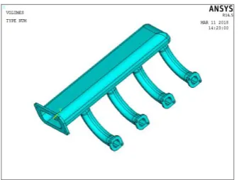
Fig.6.1 shows the geometric model of the modified Inlet Manifold
MATERIAL PROPERTIES:
There are several types of material used to make intake manifolds. The materials are cast aluminum alloy (AlSi12), magnesium alloy and polyamide composite (PA6 GF30) [14]. Locally, common intake manifolds are usually made of aluminum alloy. The materials that used in this project for analysis are AlSi12.
The materials chosen for analysis are cast aluminum alloy AlSi12 and the reason why these materials is chosen because, aluminum alloy is a common material for intake manifolds while polyamide is a new trend in automotive 17.
Cast Aluminum Alloy AlSi12:
AlSi12 alloy is a common material widely used in automotive and general engineering applications. It is also a material that most frequently encountered with in automotive intake manifolds. It consist of about 87% Al, 12% Si, and the rest are Fe, Mn, Zn, Mg, and Cu.
Material used for Inlet Manifold is Aluminum alloy (AlSi12),
Young’s Modulus: 72GPa Poisson’s Ratio: 0.3 Density: 2800 Kg/m3 Yield strength: 110MPa
Element Types used:
Name of the Element: SOLID 187 Number of Nodes: 10
Available online: http://edupediapublications.org/journals/index.php/IJR/ P a g e | 536
Element loads are described in Node and Element Loads. Pressures may be input as surface loads on the element faces as shown by the circled numbers on Figure “SOLID92 Geometry". Positive pressures act into the element. Temperatures and fluencies may be input as element body loads at the nodes.
Fig. shows the meshed model of modified Inlet Manifold
BOUNDARY CONDITIONS:
All Bolting locations are constrained in all Dof.
Pressure load is applied on inner surface of modified Inlet tubes Manifold is 0.0142Mpa.
Fig. Shows the applied constraints on bolting location
Fig. shows the applied boundary conditions and pressure of modified Inlet Manifold
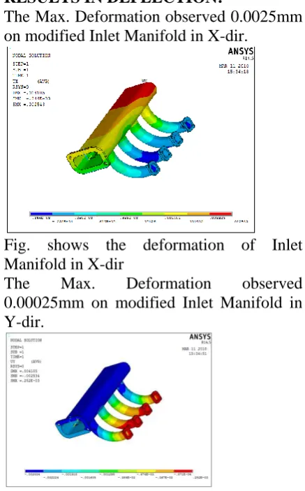
RESULTS IN DEFLECTION:
The Max. Deformation observed 0.0025mm on modified Inlet Manifold in X-dir.
Fig. shows the deformation of Inlet Manifold in X-dir
The Max. Deformation observed 0.00025mm on modified Inlet Manifold in Y-dir.
Fig.shows the deformation of modified Inlet Manifold in Y-dir
The Max. Deformation observed 0.00281mm on modified Inlet Manifold in Z-dir.
Fig. shows the deformation of modified Inlet Manifold in Z-dir
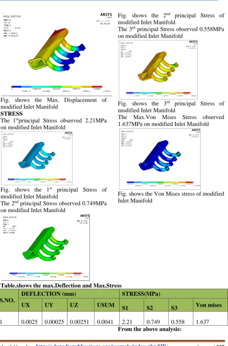
Available online: http://edupediapublications.org/journals/index.php/IJR/ P a g e | 537
Fig. shows the Max. Displacement of modified Inlet Manifold
STRESS
The 1stprincipal Stress observed 2.21MPa
on modified Inlet Manifold
Fig. shows the 1st principal Stress of modified Inlet Manifold
The 2nd principal Stress observed 0.749MPa
on modified Inlet Manifold
Fig. shows the 2nd principal Stress of modified Inlet Manifold
The 3rd principal Stress observed 0.558MPa
on modified Inlet Manifold
Fig. shows the 3rd principal Stress of modified Inlet Manifold
The Max.Von Mises Stress observed 1.637MPa on modified Inlet Manifold
Fig. shows the Von Mises stress of modified Inlet Manifold
Table.shows the max.Deflection and Max.Stress
S.NO.
DEFLECTION (mm) STRESS(MPa)
UX UY UZ USUM
S1 S2 S3 Von mises
1 0.0025 0.00025 0.00251 0.0041 2.21 0.749 0.558 1.637
Available online: http://edupediapublications.org/journals/index.php/IJR/ P a g e | 538
The Max Deflection and the Max Avg. VonMises Stress observed on the modified Inlet Manifold for applied pressure is 0.0041mm and 1.637MPa with respectively. And the Yield strength of the material metal Aluminium is 110 MPa.
Hence according to the Maximum Yield Stress Theory, the VonMises stress is less than the yield strength of the material. The design of modified Inlet Manifold is safe for the above operating loads.
RESULTS AND DISCUSSIONS
THERE IS ONE CASES TO STUDY THE STATIC ANALYSIS OF INLET MANIFOLD:
Static analysis
Table.shows the max.Deflection and Max.Stress
S.NO.
DEFLECTION (mm) STRESS(MPa)
UX UY UZ USU
M S1 S2 S3 Von mises
1 0.0078 0.00013 0.0060
0.009
9 2.44 0.99 0.58 2.25
From the above analysis:
The Max Deflection and the Max Avg. VonMises Stress observed on the Inlet Manifold for applied pressure is 0.0099mm and 2.25MPa with respectively. And the Yield strength of the material metal Aluminium is 110 MPa.
Hence according to the Maximum Yield Stress Theory, the VonMises stress is less than the yield strength of the material. The design of Inlet Manifold is safe for the above operating loads.
SECOND CASE TO STUDY STATIC ANALYSIS OF MODIFIED INLET MANIFOLD ANALYSIS :
STATIC ANALYSIS:
Table.shows the max.Deflection and Max.Stress
S.NO.
DEFLECTION (mm) STRESS(MPa)
UX UY UZ USUM
S1 S2 S3 Von mises
1 0.0025 0.00025 0.00251 0.0041 2.21 0.749 0.558 1.637 From the above analysis:
The Max Deflection and the Max Avg. VonMises Stress saw on the altered Inlet Manifold for connected pressure is 0.0041mm and 1.637MPa with individually. What's more, the Yield quality of the material metal Aluminum is 110 MPa.
Hence as per the Maximum Yield Stress Theory, the VonMises stress is not exactly the yield quality of the material. The design of altered Inlet Manifold is alright for the above working burdens.
Available online: http://edupediapublications.org/journals/index.php/IJR/ P a g e | 539
In my project we done analysis of bay complex which is utilized for delivering power transmission in truck with 2 cases. In first case, Inlet complex which comprise 415mm length frames the vonmises stress is 2.25MPa under strain condition. In second case, Inlet complex which comprise 385mm length frames the vonmises stress is 1.63MPa under strain condition. Bay complex which has length 385mm structures less von mises stress contrasted with other. So Inlet complex with length 385 mm is a best to work pressure condition.
REFERENCES
[1] C.P. Kothandara and S. Subramanyan, 1989, Heat and Mass Transfer, New age international Publishers.
[2] M.L Mathur and R.P. Sharma, 1974, I.C engine, DhanpatRai Publication.
[3] V. Ganeshan, 1999, Gas turbine, TATA McGraw-Hill.
[4] Engine Testing, Lab manuals, UPES. [5]P. K. Nag, 1981, Engineering
Thermodynamics, TATA McGraw-Hill. [6]Url-1
<http://www.energyharvestingjournal.co m/resources-profile.htm>
[7]Url-2
http://www.hq.nasa.gov/pao/history/sp-468/ch11-6.htm
[8]NSF Blue Ribbon Panel on SBES,"Simulation-based engineering science: Revolutionizing engineering