Elimination of the Single Phase Parallel Active Power Filter
Harmonic in Distribution Network
Olcay Palta
1& Hanifi Güldemir
21
Department of Technical Vocational School, Bitlis Eren University, 13000 Bitlis, Turkey
2
Department of Electrical and Electronics Engineering, Fırat University, Elazığ, Turkey
Abstract:
In this work, the harmonics of the semiconductors used in industrial applications are given. Harmonics allowed voltage and current waveforms to move away from basic waveforms cause a decrease to power factor, an increase to power losses and damage to electronic elements. Harmonics formed by non-linear loads at the source were eliminated by means of Parallel Active Filter (PAF). A non-linear single-phase load model was formed by Matlab /Simulink program, and harmonics formed at source were simulated. Harmonics were eliminated by forming at single-phase PAF simulation environment. Thus, power factor was enhanced and power losses were reduced to minimum.
Keywords
Active filters, active power filter, harmonic filtering
1.
Introduction
Power electronics have been used as switching elements in control systems in the energy sector since 1970. However, these elements produce harmonics when switching on and off depending on the switching frequency. For example, when a linear ohmic load is used independently, it does not draw reactive power; however, when used with switching elements such as thyristors or triacs, this charge draws reactive power and produces effective harmonics. Furthermore, the use of such switching elements in particular distorts the sinusoidal shape of the current and voltage waveforms. Power quality has become an important problem with the increasing use of static power converters in energy systems [1]. Nowadays, power electronic components are used more widely to increase the efficiency in the use of energy [2].
Harmonics cause various deformations in the electrically operated system elements. In plants with high harmonics;
• If the capacitors fail frequently,
• If some malfunctions occur without reason or the cause cannot be understood,
• If measuring instruments in factories sometimes do not measure correctly,
• If the switches open without cause,
• If the automation system can operate incorrectly, • If electronic card malfunctions occur continuously,
• If the neutral cables become hot due to overload and the insulation is damaged,
These and similar events may occur as a blended source. All of these events indicate the presence of harmonics that exceed many acceptable levels.
Harmonics increase power losses by reducing the power coefficient. In order to prevent losses, many studies have been carried out in scientific sense, and the trend towards solid-state lighting devices that produce not harmonic or very little harmonics instead of saving lamps in lighting area which corresponds to 25% of the energy consumption in the whole world continues [3]. In addition, they cause overheating of capacitors and electric machines, decreasing their working life, and deterioration of the counters and protective circuit elements.
Although most countries have their own harmonic standards, the most well-known is the IEEE 519 standard. The first version of the IEEE -519 standard is IEEE-519 1981, which was introduced in 1981 as the ‘IEEE Guide for Harmonic Control and Reactive Compensation ında by the IEEE Static Power Converter Committee of Industry Applications Society. This paper was revised between 1989 and 1992 and updated ics IEEE Recommended Practices and Requirements for Harmonics Control in Electric Power Systems Bu. This paper consists of a number of recommendations which have been applied more than some of the limitations [1,4].
In this study, single phase PAF is designed which can be used in distribution systems and smart grids today [5]. The mathematical model of single-phase PAF in Matlab / Simulink has been investigated and the success of harmonic removal of this filter in different loads has been investigated.
2.
Power Filters
distribution systems, minimizing the harmonics has become a necessity today [8,9].
Passive Power Filters (PF) have first emerged for this purpose. The low cost and ease of design increased the attractiveness of PGF. The more intensive use of semiconductor elements with developing technology has caused PFs to be insufficient in filtering. However, this time, the use of high success rate PAF increased in the elimination of harmonics. The disadvantage of PAF compared to PFs is that the initial cost is high. In contrast, the success of PAFs in harmonic removal eliminates these disadvantages. The PGF consists of resistors, coils and capacitors (R-L-C). The goal in PFs is to determine the L and C values to form a resonance at the frequency of the harmonic component to be destroyed [10].
Filtering techniques have been developed to minimize the impact of problems in power systems, reduce the harmonic components of line currents and voltages, and increase the power factor. PFs are commonly used in power factor correction and suppression of harmonics. PFs can only be set to filter basic harmonic frequencies, such as the 3rd and 5th harmonic currents in power system currents. They are affected by welding impedance and cause unwanted resonance problems in compensation process [11,12].
Due to the disadvantages of PF, AFs have been developed for power factor and harmonic compensation. With the inclusion of renewable energy sources and related control units in the energy system, the use of active power filters has become a necessity due to the increasing harmonic effects of the power electronics circuits with the rapid development. Active power filters are used to compensate for harmonic currents and to eliminate voltage drops [13,14]. PAF is used to suppress the harmonics generated by nonlinear loads by producing the opposite signal in the same amplitude with the capacitor used. Today, the increase of the transition to the smart grid, the network software and remote access, SCADA and artificial learning ability to gain the need for active power filters are increasing [15-20].
3.
Modeling of Single-Phase PAF
Depending on the load, it is to eliminate unwanted harmonics that occur in the current drawn from the single-phase AC source. IGBTs are used as switches T1, T2, T3, T4. In order to perform the charge-discharge process, the capacitor C is used. The DGM signal is sent to the T1 and T4 switches from the respective 1 and 4 probes, while the DGM signal is sent to the switches T2 and T3 from the 2 and 3 probes. When T1-T4 is in transmiss ion, T2-T3 is in
cut, T2-T3 is in transmission while T1-T3 is in transmission, while T1-T3 is in transmission. A single-phase PAF model flowchart designed in Figure 1 is shown.
Figure 1. Flow diagram of the designed single-phase PAF model
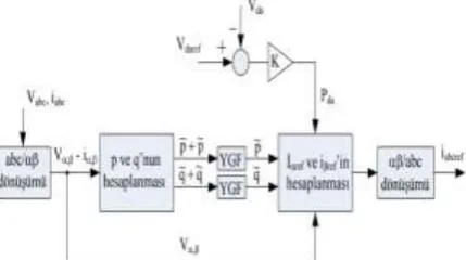
Figure 2 illustrates explanatory information about the control of the system and it is seen from this figure that alpha / beta and d / q transformations are analyzed and system sizes are analyzed. Accordingly, the dq-axis components of the current harmonics to be filtered are obtained. Reference vectors are produced in abc plane by applying reverse Park and reverse Clarke transformations to these vectors. In addition, a Proportional + Integral (PI) controller is used to keep the de-line capacitor voltage constant. The signal obtained from the output of the controller is added to the reference currents obtained from YGF [21-23].
3.1.
Simulated single-phase PAF system
model
A current signal is generated from the current sensor connected in series to the nonlinear load, depending on the voltage information from the voltage sensor connected to the voltage source and the current information of the current drawn by the filter. The harmonics generated by the reference signal are controlled. The harmonic signal generated by the nonlinear load was compared to the reference signal on the hysteresis current controller. As a result of comparison, Pulse Width Modulation (DGM) signals are generated and the switches of the inverter are activated.
3.2.
Single-phase PAF model
Figure 3 shows the single-phase PAF model. The capacitor and the resistance are connected to each other in parallel with the system and representing the nonlinear load. The PAF block consists of a filter capacitor which performs charge-discharge operations depending on the state of the switching elements. The non-linear load and the PAF have a current-limiting coil.
Va C R
S1
S2
S3
S4
Vx
+
-İy
İ1 İ3
İL
Vk
Akım sensörü
Akım ve Gerilim bilgisine dayalı referans sinyal
Ref I PWM sinyal
üreteci T1
T2
T3
T4 C
L1
L2
Figure 3. Single-phase PAF model
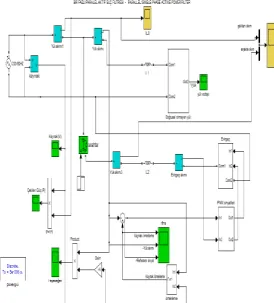
Single phase Parallel active power filter prepared in Matlab / Simulink program is designed as block diagrams and codes written when entered into related blocks can be seen. Figure 4 shows the simulated, single-phase PAF simulation detail.
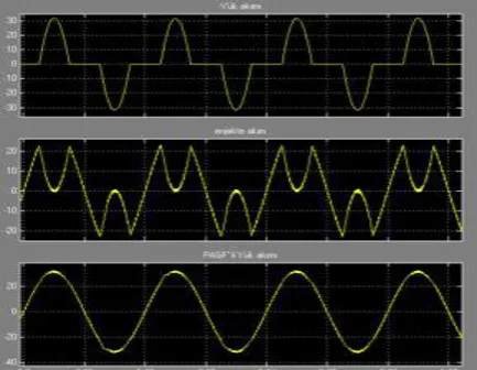
Figure 4. Single-phase PAF simulation detail Nonlinear load block formed by representing the nonlinear load consists of the inverter block, the DGM signal generator block and the reference signal generator block, which make up the PAF. In the simulation, welding current, charge current and inverter current with voltage meter, voltage meter and welding voltage values are used in control circuit. Coils L1 and L2 are used as current softening coils and are placed in the nonlinear load and in front of the inverter.
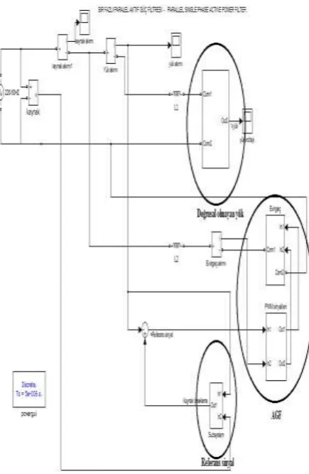
Figure 5. Simulated single phase PAF units
The second factor that affects the performance of AFs as much as the design of the power circuit is the control method. In terms of flow control methods in AFs, two main topics can be examined. The first part is the method of calculating the current reference which must be produced in order to eliminate the current produced by the harmonic source and keep the DC bus voltage at the desired value, the second part is the current control method [20-24].
Figure 6 shows the PAF control method. During the operation of the AF circuit, samples are taken from the load current (IL), the input voltage (Vs) and the filter current (IF). The area of the sampled welding current is calculated over each period. The peak value of the sine wave shape is calculated to spread this calculated area in sine wave form in each period. Figure 7 shows the reference source current when the unit sine vector obtained from the sampling of the source voltage is multiplied by the present peak value.
Figure 6. PAF control method
Figure 7. DGM signals applied to IGBTs
4.
Simulation of single-phase PAF
Simulation of the single-phase PAF The results of the non-linear load, which were originally designed in the Matlab / Simulink program, were followed by PAF to the non-linear load. The total harmonic distortion of the PAF's current in the current and in the absence of the load is investigated. The magnitudes of the circuit elements used in simulation are shown in Table 1.
Table 1. Sizes of circuit elements used in simulation
Supply voltage / hertz 220 V / 50 Hz
Non-linear load resistance 15 ohm
For non-linear load, current
softening coil 0.2 mH
Non-linear load capacitor 14 mF
For non-linear load, current softening coil
0.2mH
Inverter capacitor 25 µF
Inverter resistance 8 kΩ
For inverter, current softening coil 150mH
Figure 8 shows the current form drawn by the nonlinear load. In this study, it was aimed to minimize the THD of the non-sinusoidal current signal and to obtain a sinusoidal signal.
Figure 8. Current form drawn by nonlinear load
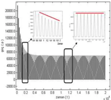
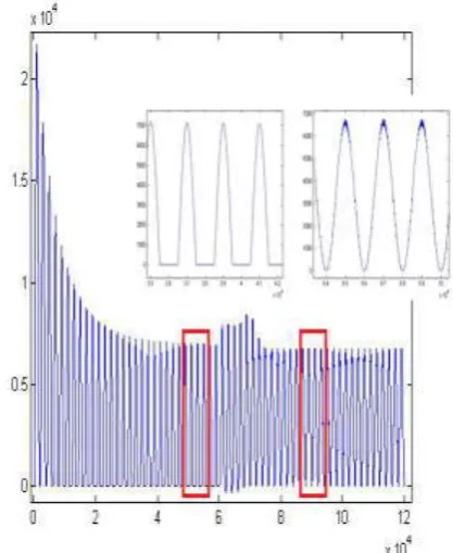
Figure 9 shows the power drawn by the nonlinear load. The harmonic current received influences the quality of the drawn power, resulting in a non-sinusoidal power signal pattern. This situation caused a loss of power.
Figure 9. Power drawn by nonlinear load
Figure 10. THD value of current drawn by nonlinear load
t = 0.3 seconds when PAF is active and the current waveform is shown in Figure 11. In the current signal drawn by the non-linear load in Figure 11, the harmonics of the current signal have decreased and become sinusoidal by the activation of PAF. The harmonic current, which is drawn with a histeless current controller, is approximated to the reference current.
Figure 11. Current signal drawn by non-linear load (PAF)
In Figure 12, the PAF was activated at t = 0.3 and the THD of the welding current at the time t = 0.4-0.6s was 1.36%. Figure 12 shows the THD change when PAF is active.
Figure 12. Change of THD when PAGF is active
The quality of the power drawn to the nonlinear load in Fig. 13 improved with the activation of the modeled PAF. At first, the load current approaches the reference current and the harmonic signal appears to enter the sinusoidal form.
Figure 13. Power drawn by non-linear load
with the injected current applied by PAF. Figure 14 shows the non-linear load of the injected current applied by the filter against the harmonic current. This shows that the power factor has improved and the approximate non-harmonic current form has been reached.
Figure 14. Injected current applied by the filter against the harmonic current drawn by the non-linear load
Table 2 shows the system's unfiltered and PAF THD values according to the current flow.
Table 2. Unfiltered and PAF THD values of the system according to the current flow
PAF t = 0.3s later when activated
Current drawn rms
THD without filter t = 0.1s-0.3s
Filtered THD t = 0.4s-0.6s
85.3 14.19 10.19
57.6 33.95 6.74
45.7 44.35 1.29
38.7 51.34 1.03
27.19 64.79 1.13
21.7 71.92 1.1
16.3 79.44 1.48
13.5 83.31 1.53
11.2 86.48 2
Referring to the graph in Figure 15, the modeled PAF was found to be effective at low power loads such as 15 A to 45 A.
Figure 15. Unfiltered and PAF THD values according to the drawn currents
5.
Results and Discussion
In this study, PAF was used and the filter was applied to 220VAC, 50 Hz sinusoidal single phase load. In the control method of PAF, the control method is determined by reference to the welding voltage, the load current and the filter current.
Nowadays, the rapid development of technology, in parallel, the low-power systems to gain sensitivity, has created the need to remove the harmonics formed in the network connected to single-phase systems. In order to increase the efficiency and energy quality of the system, it is necessary to minimize the reactive component of the power drawn from the source and suppress the harmonics. The PGFs used in the suppression of harmonics were found to suppress the harmonics only at certain intervals and therefore did not give the desired performance. PAF successfully eliminated the system harmonics. PAF has been found to provide successful results according to IEEE-519 1992 standard current harmonic limitations.
In this study, intelligent optimization techniques can be used to determine the optimal components of the SAPF simulation circuit.
In addition, future studies have to investigate the fluctuations occurring during the triggering of semiconductor IGBTs used in the SAPF circuit depending on their current aspects. In this way, the effects of harmonics on the system can be minimized.
6.
References
[1] Siğergök, B. (2009). Uzay vektör darbe genişlik modülasyon denetimli aktif filtre devrelerinin modellenmesi ve benzetimi, Yüksek Lisans Tezi, Fırat
Üniversitesi, Fen Bilimleri Enstitüsü, Elazığ.
[3] Cengiz, MS., Cengiz, Ç., Mamiş MS. 2018. Contribution of Reflector Design formed by Numeric Calculations to Energy Efficiency, Uluslararası GAP
Yenilenebilir Enerji Ve Enerji Verimliliği Kongresi - 2018.
[4] Rendusara, D., Von Jouanne, A., Enjeti, P., Paice, D.A. (1996). Design considerations for 12-pulse diode rectifier systems operating under voltage unbalance and preexisting voltage distortion with some corrective measures, IEEE Transactions on Industry Applications, 32(4), 1293-1303.
[5] Çöteli, R., Uçar, F., Dandıl, B., Ata F., Paralel Aktif Güç Filtresinin Denetimi İçin Farklı Referans İşaret Çıkarma Yöntemlerinin İncelenmesi, The 6th International Advanced Techno. Symposium, 111-119, 2011, Elazığ.
[6] Efe, SB. (2015). Analysis and elimination of harmonics by using passive filters, Bitlis Eren Universty Journal of Science & Technology, 5(2), 48-51.
[7] Kumar, D., Zare, F. Analysis of Harmonic Mitigations using Hybrid Passive Filters", 16th International Power Electronics and Motion Control Conference and Exposition, 945-951, 21–24 Sept 2014.
[8] Efe SB. Harmonic Filter Application for an Industrial Installation, IEEE The 13th Inter. Conf. on Engineering of Modern Electric Systems, 11-12 June 2015, Oradea.
[9] Özdemir, E., Özdemir, Ş., Kale M., Aktif Güç Filtresi ile Harmonik ve Reaktif Güç Kompanzasyonu, Eleco’2002 Elektrik-Elektronik - Bilgisayar Mühendisliği Sempozyumu ve Fuarı, 18-22 Aralık 2002, Kocaeli.
[10] Hoang T.T., Cho M.Y., Vu Q.T. (2018). A novel perturbed particle swarm optimization-based support vector machine for fault diagnosis in power distribution systems, Turkish Journal of Electrical Engineering & Computer Sciences, 26(1), 518 – 529.
[11] Chen, D., Xie, S. Review of the Control Strategies Applied to Active Power Filters, IEEE Int. Conf. On Electc. Utility Deregation, 666-670, 2004, Hong Kong.
[12] Çolak, İ., Kaplan O. (2011). Bir fazlı paralel aktif güç filtreleri için sensörsüz DA gerilim kontrolü, Gazi Üniversitesi Mühendislik Mimarlık Fakültesi Dergisi,
26(2), 223-232.
[13] Dursun, M., (2005). Doğrusal olmayan sistemler için bir seri aktif güç filtresi tasarımı ve analizi, Politeknik Dergisi 6(1), 523-530.
[14] Baharom, R., Hamzah, M.K., Hamzah, N.R., Ismail, N.F. and Abu Hasim, A.S., Computer Implemented Model of Single Switched Single-Phase Parallel Active Power Filter, 2nd International Conference on Mechanical and Electronics Engineering, 31-37, 2012, Kyoto..
[15] Aleem, S.H.E.A. Zobaa, A.F., Aziz, M.M.A. (2012). Optimal C-Type Passive Filter Based on Minimization of the Voltage Harmonic Distortion for Nonlinear Loads,
IEEE Transactions on Industrial Electronics, 59(1), 281-289.
[16] Avcı, T., (2008). Akım kaynaklı aktif güç filtresi için çeşitli kontrol yöntemlerinin karşılaştırılması, Yüksek
Lisans Tezi, Hacettepe Üniversitesi, Fen Bilimleri Enstitüsü, Ankara.
[17] Rahman, N.F.A., Hamzah, M.K., Noor, S.Z., M., Hasim, A.Ş.E. (2009). Single-Phase Hybrid Active Power Filter Using Single Switch Parallel Active Filter and Simple Passive Filter, The Eighth International Conference on Power Electronics and Drive Systems, 2-5, Taipei.
[18] Arı, D., Çıbuk, M., Ağgün, F. (2017). Effect of relay-priority mechanism on multi-hop wireless sensor networks,
Bitlis Eren University Journal of Science and Technology, 7(2), 145–153.
[19] Çıbuk, M., Balık, H.H., (2010). A Novel Communication Application Model for Biomedical Networks, Fırat Ün. Mühendislik Bilimleri Dergisi Fırat
Univ. Journal of Enginering, 22(1), 95-109.
[20] Ertugrul Ö.F. (2016). Forecasting electricity load by a novel recurrent extreme learning machines approach.
International Journal of Electrical Power & Energy Systems, 78(2), 429–435.
[21] Cengiz MS., Mamiş MS. (2015). Solution Offers for Efficiency and Savings in Industrial Plants, Bitlis Eren Universty Journal Science & Technolgy, 5(1), 24-28.
[22] Yurci Y., Kaynaklı M., Palta O., Efe SB., Cengiz Ç. (2016). The Performance-Cost Effect of the SCADA System on Distribution Networks, IOSR Journal of Electrical and Electronics Engineering, 11, 6, 32-38.
[23] Kale, M., (2004). Paralel Aktif Güç Filtresi ile Harmonik Akım ve Reaktif Güç Kompanzasyonu, Yüksek Lisans Tezi, Kocaeli Üniversitesi, Fen Bilimleri Enstitüsü,
Kocaeli.
[24] Lascu, C., Asiminoaei, L., Boldea, I., Blaabjerg, F. (2009). Frequency response analysis of current controllers for selective harmonic compensation in active power filters, IEEE T Ind Electron, 56(2), 337-347..
Received: 12th Apr. 2018; Accepted: 2th Oct. 2018;