Fracture Analysis of Pipe of Tapered Thickness
#1 G.Sandeep, P.G Scholar#2 B.Praveen Kumar, Assistant Professor
Department Of Mechanical Engineering
Talla Padmavathi College Of Engineering,Kazipet,Warangal,T.S.
ABSTRACT
In this thesis, the clamped – free pipe
tapered thickness effect on the
deformations, stresses, stress intensity factors and frequencies is determined analytically for two cases. The pipe is conveying water. In the first case the pipe’s wall thickness is constant at clamped end and it is changed at free end changes depending on different thickness ratio. In the second case the pipe’s thickness at free end is constant and it is changed at clamped end at different thickness ratio. The pipe has a constant inner radius and length. The thickness ratios considered in this project are 0.6, 0.9 and 1. 3D models of the pipe are done in Creo 2.0. Static, Modal, Fracture analyses are done in Ansys 14.5.
I.INTRODUCTION
A pipe is a hollow cylinder or tubular section, normally but not certainly of circular cross-section, mainly utilized mainly for conveying substances that can flow — gases and liquids (fluids), powders, small solids masses and slurries. It can be utilized also for structural applications; solid pipe is less stiff / unit weight than hollow pipe.
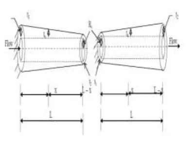
Fig 1: Introducing a Taper in the Pipe Carrying Fluid
Fig (1-a) Cantilever pipe of tapered Fig (1-b) Cantilever pipe of tapered Thickness
t2/t1≤1 Thickness t 1/t 2≤1
II.LITERATURE SURVEY
Nawal H. Al Raheimy [1] studied the tapered thickness effect on the clamped – free pipe free transverse vibration which has cross section of uniform circular conveying water by employing Raighly – Ritz method for two cases, the 1st case involves a pipe having a constant wall thickness at clamped end and changing the thickness at free end according to the thickness ratio. In the 2nd case at free end thickness is constant whereas the clamped end thickness is changed by ratio. For uniform section of the pipe the natural frequency is decreased when the water velocity is increased from 0 to critical velocity.
investigation of residual stresses at pipe girth welds effect on the vibration characteristics & stability a new analytical model was. For evaluating pressure and velocity distributions in a single phase fluid flow a FE simulation was presented. Jwege & Zahid[3] investigated the end conditions effect on the pipe vibration characteristics which is conveying fluid with various cross sections like (sudden enlargement & sudden contraction). Diverse end pipe supports (simply, flexible & rigid) were selected for investigation of the natural frequencies & their respective mode shapes. Also, investigation of some design parameters such as pipe length, diameter, pipe material effect and the fluid velocity effect were done.
III.3D MODELS OF PIPE WITH
DIFFERENT THICKNESS
RATIOS
The reference for the modelling is taken from the journal paper “Nawal H. Al Raheimy, Theoretical Study on Pipe of Tapered Thickness with an Internal Flow to Estimate Natural Frequency International Journal of Mechanical Engineering and Technology, 7(2), 2016, pp. 105–120” specified as [1] in References chapter.
Case 1:- Thickness Ratio --- 𝒕𝟐 𝒕
𝟏
⁄ = 𝟎. 𝟔
Fig 2: - Extrude pipe with 𝑡2 𝑡 1
⁄ = 0.6
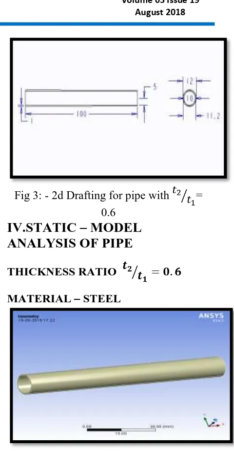
Fig 3: - 2d Drafting for pipe with 𝑡2 𝑡 1
⁄ =
0.6
IV.STATIC – MODEL
ANALYSIS OF PIPE
THICKNESS RATIO 𝒕𝟐 𝒕
𝟏
⁄ = 𝟎. 𝟔
MATERIAL – STEEL
Fig 4: - Imported model of pipe with t2/t1 = 0.6
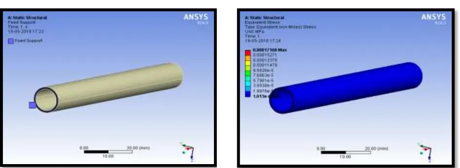
Fig 6: - Fixed support is applied at smaller end of pipe with t2/t1 = 0.6
Fig 7: Pressure applied inside the pipe
Fig 8: - Total deformation of pipe using Steel material with t2/t1 = 0.6
Fig 9: - Equivalent stress of pipe using Steel material with t2/t1 = 0.6
Fig 10: - Equivalent strain of pipe using Steel material with t2/t1 = 0.6
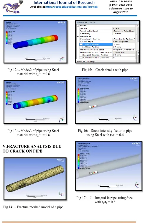
Fig 12: - Mode-2 of pipe using Steel material with t2/t1 = 0.6
Fig 13: - Mode-3 of pipe using Steel material with t2/t1 = 0.6
V.FRACTURE ANALYSIS DUE
TO CRACK ON PIPE
Fig 14: – Fracture meshed model of a pipe
Fig 15: – Crack details with pipe
Fig 16: - Stress intensity factor in pipe using Steel with t2/t1 = 0.6
VI.STATIC STRUCTURAL ANALYSIS
FRACTURE ANALYSIS
VII.CONCLUSION
By observing Static analysis results, the deformation is reducing by increasing the thickness ratio. The deformation values are less when Steel is used. The stress is reducing by increasing the thickness ratio. 0.00E+00
1.00E-08
0.6 0.9 1
D EFORM A TIO N (m m ) THICKNESS RATIO
COMPARISON OF
DEFORMATION VALUES OF
PIPES WITH DIFFERENT
THICKNESS RATIOS AND …
Steel Aluminum alloy 7475 0 0.0002
0.6 0.9 1
STRE
SS
(M
Pa)
THICKNESS RATIO
COMPARISON OF STRESS
VALUES OF PIPES WITH
DIFFERENT THICKNESS
RATIOS AND DIFFERENT …
Steel
Aluminum alloy 7475
0.00E+00 1.00E+03
0.6 0.9 1
D EFORM A TIO N (m m ) THICKNESS RATIO
COMPARISON OF
DEFORMATION VALUES OF
PIPES WITH DIFFERENT
THICKNESS RATIOS AND
DIFFERENT MATERIALS AT …
Steel Aluminum alloy 7475 0.00E+00 1.00E+03
0.6 0.9 1
FRE QUE N CY (H z) THICKNESS RATIO
COMPARISON OF FREQUENCY
VALUES OF PIPES WITH
DIFFERENT THICKNESS RATIOS
AND DIFFERENT MATERIALS AT …
Steel
Aluminum alloy 7475
0.00E+00 2.00E+06
0.6 0.9 1
SI
FS
-K1
THICKNESS RATIO
COMPARISON OF
SIFS-K1VALUES OF PIPES WITH
DIFFERENT THICKNESS
RATIOS AND DIFFERENT …
Cast iron
Aluminum alloy 7475
0.00E+00 2.00E+16
0.6 0.9 1
J
INT
THICKNESS RATIO
COMPARISON OF JINT
VALUES OF PIPES WITH
DIFFERENT
THICKNESS RATIOS
AND DIFFERENT …
Cast iron
The stress values are less when Steel is used. By observing Modal analysis results, the deformation is reducing by increasing the thickness ratio. The deformation values are less when Steel is used. The frequency is reducing by increasing the thickness ratio. The frequency values are less when Steel is used. By observing fracture analysis results, the stress intensity factors are reducing by increasing the thickness ratio and less when Steel is used. The J-Integral values are increasing by increasing the thickness ratio. The J-Integral value is more when Cast Iron is used.
REFERENCES
[1] Nawal H. Al Raheimy, Theoretical Study on Pipe of Tapered Thickness with an Internal Flow to Estimate Natural Frequency, International Journal of Mechanical Engineering and Technology, 7(2), 2016, pp. 105–120.
[2] Nabeel K. Abid Al-Sahib a, Adnan N. Jameel b, Osama F. Abdulateef a*, Investigation into the Vibration Characteristics and Stability of a Welded Pipe Conveying Fluid, J. (JJMIE), 4(3), 2010.
[3] Mohsin J. Jwege & Zahid I. Mohammed, Vibration characteristics of different cross section pipes with different end conditions, Journal of Eng, & Tech., 28(8), 2010, 1634-1654.
[4] Wang & Bloom, Stability issues of concentric pipes containing steady and pulsatile flows, J.F. and structure, 2001.
[5] A. Marzania, M. Mazzottia, E. Viola, P. Vittorib & I. Elishakoffb*,"FEM Formulation for Dynamic Instability of Fluid-Conveying Pipe on Non uniform Elastic Foundation", J. of Mechanics Based Design of Structures and Machines, Vol. 40, Issue 1, pp. 83-95, 2011.
[6] A. K. Misra, M. P. Pa¨ıdoussis, and K. S. Van, “On the dynamics of curved pipes transporting fluid. Part I: inextensible theory, “Journal of Fluids and Structures, vol. 2, no. 3, pp. 221–244, 1988
[7] H.-B. Zhai, Y.Wu,Y.-S. Liu, and Z.-F.Yue, “In-plane dynamic response analysis of curved pipe conveying fluid subjected to random excitation,” Nuclear Engineering and Design, vol. 256,pp. 214– 226, 2013.
[8] Q. Ni, M. Tang, Y. Wang, and L. Wang, “In-plane and out-ofplanedynamics of a curved pipe conveying pulsating fluid, “Nonlinear Dynamics, vol. 75, no. 3, pp. 603–619, 2014.
[9] A. R. Setoodeh and S. Afrahim, “Nonlinear dynamic analysis of FG micro-pipes conveying fluid based on strain gradient theory,” Composite Structures, vol. 116, no. 1, pp. 128–135, 2014.