AT&T
AT&T Business Communications Systems
subject:
Addendum 1 (555-025-101ADD) for
DS1/DMI/ISDN-PRI Reference
(555-025-101)
date:
December 1990
AT&T
from:
The packet of addendum information enclosed with this cover memo includes any necessary
replacement, supplement, and errata pages to DS1/DMI/ISDN-PRI Reference. It contains both
new information and information from any previous addenda to the document. By
incorporating the addendum as instructed on the next page, you can update your copy of the
document to be current with the latest issue of the System 85 or DEFINITY® Generic 2.1
Communications System.
When you have incorporated the addendum, be sure to insert the addendum description
into your document behind the title page, where it will serve as a record that the
This addendum includes necessary replacement, supplement, and errata pages to DS1/DMI/ISDN-PRI Reference (555-025-101), Issue 4, dated April, 1990. Incorporate the addendum as instructed below to update your copy of the document to be current with the latest issue of the System 85 or DEFINITY® Generic 2.1 Communications System. Then insert this addendum description into the document,
behind the title page and before the table of contents. It will serve as a record that your document has been addended.
Nature of the Document Changes
The general nature of the changes to your document is as follows: This packet contains information about the following features:
●
●
●
●
Integrated Telemarketing Gateway Interface (ITGI), Integrated Telemarketing Gateway (ITG), and ISDN Advantage including general descriptions on these unique applications of PRI trunks
Look-Ahead Interflow, while currently documented on page 1-28, has expanded general descriptive information and additional administrative support information
Appendix E, Trunk Type and signaling Type Compatibility Tables is a new group of trunk tables Miscellaneous cosmetic changes
Nature of the Addendum Pages
The addendum pages in this package may be of up to three types: ●
●
●
Replacement pages contain new or changed information, indicated by margin rule marks in text or hand symbols or in tables and figures. They are to replace existing pages in your document. Supplement pages contain all new information. They are to be added to your document.
Errata pages contain lists or descriptions of corrections to be noted by hand in your document.
Instructions for Handling Addendum Pages
Instructions for handling the addendum pages are as follows:
ADDENDUM 1 (December 1990) to 555-025-101, Issue 4
ADD-2 ADDENDUM DESCRIPTION
Chapter Type of Change Pages Affected Instructions
Table of Contents Replacement all pages Remove all pages from document and discard; replace with new Table of Contents supplied.
About This Replacement all pages Remove all pages from document and Document discard; replace with new About This
Document supplied.
Chapter 1 Replacement 1-3 to 1-6 Remove pages 1-3 to 1-6 from document and discard; replace with those supplied.
Chapter 1 Errata 1-9 Make corrections by hand on page 1-9 of document. Add the following words to the end of the second paragraph in the D-Channels heading:
Up to 479 B-Channels may be controlled by a single D-channel.
Chapter 1 Replacement 1-21 to 1-32 Remove pages 1-21 to 1-32 from document and discard; replace with pages 1-21 to 1-34 supplied.
Chapter 2 Replacement 2-1 to 2-2 Remove pages 2-1 to 2-2 from document and discard; replace with those supplied.
Chapter 2 Replacement 2-11 to 2-16 Remove pages 2-11 to 2-16 from document and discard; replace with those supplied.
Chapter 3 Replacement all pages Remove all pages from document and discard; replace new chapter supplied.
Chapter 5 Replacement 5-29 to 5-32 Remove pages 5-29 to 5-32 from document and discard; replace with those supplied. Chapter 6 Replacement 6-1 to 6-8 Remove pages 6-1 to 6-8 from document
Chapter Type of Change Pages Affected Instructions
Chapter 7 Replacement all pages Remove all pages from document and discard; replace new chapter supplied. (Retain and place sub-chapter tabs appropriately.)
Chapter 8 Replacement 8-7 to 8-8 Remove pages 8-7 to 8-8 from document and discard; replace with those supplied. Appendix D Replacement all pages Remove all pages from document and
discard; replace with new appendix supplied.
Appendix E Supplement n/a Add new appendix to document.
Index Replacement all pages Remove all pages from document and discard; replace with new Index supplied.
CONTENTS
ABOUT THIS DOCUMENT
PURPOSE
INTENDED AUDIENCES
PREREQUISITE SKILLS AND KNOWLEDGE HOW THIS DOCUMENT IS ORGANIZED HOW TO USE THIS DOCUMENT TRADEMARKS AND SERVICE MARKS RELATED SOURCES
HOW TO MAKE COMMENTS ABOUT THIS DOCUMENT
1. INTRODUCTION
FUNDAMENTALS OF DS1 SIGNALS Channels
Framing Formats Signaling Types Line-Coding Formats IMPORTANT CONCEPTS
Common-Channel Signaling Alternate Voice/Data (AVD) Trunks Bearer Capability (BC)
ISDN Call Processing CBC Service Selection
Networking Restrictions and ISDN-PRI Limitations
2. NETWORK CONNECTIONS AND CONFIGURATIONS
NETWORK DIFFICULTIES Hyperactivity Glare
xxi
xxi xxii xxii xxii xxiv xxiv xxiv xxv
1-1
1-1 1-7 1-10 1-14 1-16 1-22 1-23 1-23 1-23 1-27 1-30 1-32
2-1
DS1/DMI PRIVATE-NETWORK CONNECTIONS
Generic 1, Generic 2, System 75, or System 85 to Another System Host Computer to Another System
2-3 2-3 2-3 IBM® IDNX Multiplexer to Another System
Other Vendor Digital Switch to Another System Analog Switch to Another System
OPS to Another System Via a D4-Channel Bank DS1/DMI PUBLIC-NETWORK CONNECTIONS
4ESS to Another System (Special-Access Connection) 5ESS to Another System
DACS to Another System
Analog CO to Another System Via a D4-Channel Bank DS1/DMI TERMINAL-EQUIPMENT CONNECTIONS
CDM
CEM to a BCM32000
2-4 2-4 2-5 2-5 2-6 2-6 2-7 2-8 2-8 2-9 2-9 2-10
ISDN-PRI PRIVATE-NETWORK CONNECTIONS 2-12
System 85 R2 to a System 85 R2V4, Generic 1, or Generic 2 2-12 System 85 or Generic 2 ISDN-PRI to Another Vendor’s Digital Switch 2-13
ISDN-PRI PUBLIC-NETWORK CONNECTIONS 2-13
System 85 R2V4, Generic 1, and Generic 2 to a 4ESS 2-13 System 85 R2V4, Generic 1, or Generic 2 to a DACS 2-15
System 85 or Generic 2 ISDN-PRI to a 5ESS 2-15
ISDN-PRI INTRA-SWITCH CONNECTIONS 2-16
Generic 2 ISDN-PRI with the Integrated Telemarketing Gateway Interface 2-16
AT&T 6500 ISDN Advantage 2-19
3. DS1 TRANSMISSION AND CABLING
METALLIC CABLING OPTIONS DSX-1 Distance Limitations
Network Channel Terminating Equipment (NCTE) On-Premises Cabling
Off-Premises Cabling NONMETALLIC CABLING OPTIONS
3-1
CONTENTS v
CEM AND CDM CABLING CONFIGURATIONS LINE EQUALIZER AND COMPENSATION SETTINGS
System 85 Traditional Modules
3-11 3-13 3-13 3-13 Generic 1 and Generic 2 Universal Modules
4. THE DIGITAL LOSS PLAN
LOSS-PLAN IMPLEMENTATION AND PROVISIONING Generic 2
Generic 1
PORT-TO-PORT LOSS VALUES DS1/DMI/ISDN-PRI PORT LOSSES
TERMINATING A DS1 AT A CHANNEL BANK Tie Trunk Ports
CO DID Trunk Ports OPS Ports
5. SYNCHRONIZATION OF DIGITAL FACILITIES
THE NEED FOR SYNCHRONIZATION SYNCHRONIZATION HIERARCHY
System 85 and Generic 2 Synchronization Architecture System 85 and Generic 2 Synchronization Software Operation
CHANGES TO THE SCS SOFTWARE MADE AVAILABLE VIA SOFTWARE PATCHES System 75 and Generic 1 Synchronization Architecture
System 75 and Generic 1 Synchronization Software Operation The External Synchronization Clock
NETWORK SYNCHRONIZATION AND ENGINEERING Selecting a Timing Source for the Switch Internal Reference Selection Rules External-Reference Selection Rules
AVAILABILITY OF SYNCHRONIZATION SOURCES CONCLUSIONS ON SYNCHRONIZATION
USE OF GENERIC 2 AS A SYSTEM CLOCK REFERENCE
4-1
4-2 4-2 4-3 4-4 4-6 4-6 4-6 4-6 4-7
5-1
ISDN-PRI Trunk Facilities
Line-Only Mode DS1/DMI-BOS (ANN11 or TN767)
Line+Trunk Mode DS1/DMI-BOS (ANN35 or TN767 with TN555) DMI-MOS (ANN35 or TN767 with TN555)
USE OF GENERIC 1 AS A SYSTEM CLOCK REFERENCE Trunk-Mode ISDN-PRI (TN767)
Trunk-Mode Interface (ISDN-PRI + Robbed Bit) (TN767) Line-Only Mode DS1/DMI-BOS (TN767)
Trunk-Mode DS1/DMI-MOS (TN767)
6. PORT TYPES/INSTALLATION COMPATIBILITIES
GENERIC 1 DS1/DMI-BOS Operating Mode Supported Port Types GENERIC 1 ISDN-PRI
SYSTEM 85 DS1, TRADITIONAL MODULES (ANN11) Operating Modes
Line+Trunk Mode Port Grouping Rules Supported Port Types
SYSTEM 85 DS1 OR DMI-MOS, TRADITIONAL MODULES (ANN35) Operating Mode
Port Grouping Rules Supported Port Types
7. ADMINISTRATION OPTIONS AND REQUIREMENTS
SYSTEM 85 (R2V1 THROUGH R2V4)
Procedure 275 Word 4: ISDN Service — Enable/Disable Procedure 276 Word 1: Other Feature Groups Procedure 250 Word 1: DS1 — Carrier Designation Procedure 260 Word 1: DS1/DMI/ISDN-PRI Physical Interface Procedure 262 Word 1: ISDN Board Parameters
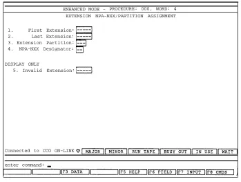
Procedure 354 Word 3: NPA-NXX Digits Assignment
5-29 5-29 5-30 5-30 5-30 5-30 5-31 5-31 5-31
6-1
6-4 6-4 6-4 6-5 6-6 6-6 6-10 6-10 6-13 6-13 6-14 6-14
7-1
CONTENTS vii
Procedure 000 Word 4: Procedure 210 Word 2: Procedure 010 Word 4: Procedure 100 Word 1: Procedure 100 Word 2: Procedure 100 Word 3: Procedure 101 Word 1: Procedure 103 Word 1: Procedure 116 Word 1: Procedure 012 Word 1: Procedure 012 Word 2: Procedure 012 Word 3: Procedure 309 Word 1: Procedure 309 Word 5: Procedure 321 Word 1: Procedure 321 Word 5: Procedure 107 Word 1: Procedure 108 Word 1: GENERIC 2
Procedure 275 Word 4: Procedure 276 Word 1: Procedure 250 Word 1: Procedure 260 Word 1: Proecdure 262 Word 1: Procedure 262 Word 2: Procedure 262 Word 3: Procedure 280 Word 1: Procedure 354 Word 3: Procedure 000 Word 3: Procedure 000 Word 4: Procedure 210 Word 2: Procedure 014 Word 1: Procedure 014 Word 2: Procedure 010 Word 4:
NPA-NXX Index Designator
LDN, NPA, and NNX Attendant Partition Assignments Line Side (B-Channel) BC and ISDN Routing Options Trunk Group Type, Signaling, and Dial Access (ID) Code Trunk Group Data Translations
ISDN Trunk Group Signaling Options
ISDN Trunk Group, CDR, Digital Loss Plan, and AVD Assignments Trunk Group Digit Collection and Trunk-Side BC
DS1/DMI/ISDN-PRI Trunk Assignments Name Database
Name Database Name Database
ARS Assignments and IXC/ISDN Network Identifier ARS and ISDN Trunk — Network Characteristics AAR Assignments and IXC/ISDN Network Identifier AAR and ISDN Trunk — Network Characteristics ISDN Trunk Verification by Terminal, Attendant, and ATMS ISDN Trunk Group Terminating Test Line Number (Digits)
ISDN Service — Enable/Disable Other Feature Groups SC/DS1 — Carrier Designation DS1/DMI/ISDN-PRI Physical Interface Additional DMI-MOS/ISDN-PRI Facility Options ISDN-PRI D-Channel Backup
ISDN-PRI Codeset Map Assignments ISDN-PRI Receive/Transmit Codeset Mapping NPA-NXX Digits Assignment
Line-Side BCCOS Designator NPA-NXX Index Designator
LDN, NPA, and NNX Attendant Partition Assignments BCCOS Routing Options
BCCOS Data Options
Line Side (B-Channel) ISDN Routing Options
Procedure 100 Word 1: Procedure 100 Word 2: Procedure 100 Word 3: Procedure 101 Word 1: Procedure 103 Word 1: Procedure 116 Word 1: Procedure 012 Word 1: Procedure 012 Word 2: Procedure 012 Word 3: Procedure 279 Word 1: Procedure 309 Word 1: Procedure 309 Word 5: Procedure 321 Word 1: Procedure 321 Word 5: Procedure 107 Word 1: Procedure 108 Word 1:
Trunk Group Type Signaling and Dial Access (ID) Code Trunk Group Data Translations
ISDN Trunk Group Signaling Options ISDN Trunk Group, CDR, and Digital Loss Plan Network Trunk Group Translations
DS1/DMI/ISDN-PRI Trunk Assignments Name Database
Name Database Name Database Network Facilities Coding ARS Route Tables ARS-ISDN BCCOS AAR Tables (Generic 2)
AAR-ISDN and Other Feature Parameters
ISDN Trunk Verification by Terminal, Attendant and ATMS ISDN Trunk Group TTL Number (Digits)
SYSTEM 75 (R1V2 AND R1V3) Network Synchronization Options
Network Facilities — ISDN-PRI Applications Trunk Group/Trunk Group Members GENERIC 1
DS1 Circuit Pack Options
Network Synchronization Options — DS1 and ISDN-PRI Applications Trunk Group/Trunk Group Members — DS1 Trunk Applications Processor Interface Data Module — ISDN-PRI Applications Processor Channel Assignments — ISDN-PRI Applications Interface Links — ISDN-PRI Applications
Trunking Considerations — ISDN-PRI Applications Network Facilities — ISDN-PRI Applications Trunk Group — ISDN-PRI Trunk Applications
Trunk Group Usage Allocation — ISDN-PRI Applications
Usage Allocation Plan Assignment Schedule — ISDN-PRI Applications Trunk Group Member Assignments — ISDN-PRI Trunk Applications SID Prefix Table — ISDN-PRI Applications
CONTENTS ix
Routing Patterns — ISDN-PRI Applications Hunt Group — ISDN-PRI Applications
Terminating Extension Group — ISDN-PRI Applications Signaling Group — ISDN-PRI Applications
8.
7-160 7-163 7-164 7-165
MAINTENANCE AND ALARMS
GENERIC 1 AND GENERIC 2 ISDN-PRI MAINTENANCE PHILOSOPHY GENERIC 2 MAINTENANCE CAPABILITIES AND CONCERNS
Generic 2 Maintenance Procedures
Summary of Generic 2 Maintenance Capabilities
GENERIC 1 MAINTENANCE CAPABILITIES AND CONCERNS Generic 1 Maintenance Procedures
Summary of Generic 1 Maintenance Capabilities ALARMS
Circuit Pack Alarms Facility Alarms
A. ADMINISTRATION REQUIREMENTS
B. SAMPLE INSTALLATION AND MAINTENANCE PROBLEMS
TRANSLATIONS-BASED PROBLEMS TRUNKS AND TRUNK GROUPS
CDMs CEMs
D4-Channel Banks
SYNCHRONIZATION-RELATED PROBLEMS Loss of or No Synchronization Leavenworth Loop
D4 Synchronization Problems Digital CO Synchronization Problems DACS
8-1
8-1 8-1 8-2 8-5 8-5 8-6 8-7 8-7 8-7 8-8
A-1
B-1
TYPICAL PHYSICAL INTERFACE CONNECTION PROBLEMS B-13
Specific Cabling Options B-17
System 85 DS1/DMI to System 85 DS1/DMI — Colocated Arrangement B-18 System 85 DS1/DMI to System 75 DS1/DMI — Colocated Arrangement B-20
System 85 DMI to Host Computer B-21
System 85 DS1/DMI Direct to a NCTE B-22
System 85 DS1/DMI-BOS to a CEM or CDM B-22
C. ADMINISTRATIVE PROCEDURE SUMMARY
PROCEDURE 000 WORD 3 (Generic 2 Only)
PROCEDURE 000 WORD 4 (System 85 R2V4 & Generic 2) PROCEDURE 010 WORD 4 (System 85 R2V4 & Generic 2)
ISDN Routing Parameters (System 85 R2V4 & Generic 2) BC (System 85 R2V4 Only)
PROCEDURE 012 (System 85 R2V4 & Generic 2) PROCEDURE 100 WORD 1 (System 85 R2V4 & Generic 2) PROCEDURE 100 WORD 2 (Generic 2 Only)
PROCEDURE 100 WORD 3 (System 85 R2V4 & Generic 2) PROCEDURE 103
PROCEDURE 107 WORD 1 (System 85 R2V4 & Generic 2) PROCEDURE 108 WORD 1 (System 85 R2V4 & Generic 2) PROCEDURE 116 WORD 1 (System 85 R2V4 & Generic 2) PROCEDURE 210 WORD 2 (System 85 R2V4 & Generic 2) PROCEDURE 260 WORD 1 (System 85 R2V4 & Generic 2) PROCEDURE 262 WORD 1 (System 85 R2V4 & Generic 2) PROCEDURE 262 WORD 3 (Generic 2 Only)
PROCEDURE 275 WORD 4 (System 85 R2V4 & Generic 2) PROCEDURE 279 WORD 1 (Generic 2 Only)
PROCEDURE 280 WORD 1 (Generic 2 Only)
PROCEDURE 309 WORD 5 (System 85 R2V4 & Generic 2) Field 4, ISDN Trunk Type
Field 5, Network Service Value BC (System 85 R2V4 and Generic 2)
C-1
CONTENTS xi
PROCEDURE 321 WORD 5 (System 85 R2V4 & Generic 2) C-17 PROCEDURE 354 WORD 3 (System 85 R2V4 & Generic 2) C-17
PROCEDURE 420 (System 85 R2V4 & Generic 2) C-18
D. TRUNK TYPE AND SIGNALING TYPE COMPATIBILITY TABLES
E. TIE TRUNK SETTINGS
System 85 Administration Settings Generic 1 Administration Settings
Administration Summary
System Parameters - Customer Options Screen Settings Feature-Related System Parameters Screen Settings Maintenance-Related System Parameters Screen Settings Dial Plan Record Screen Settings
DS1 Circuit Pack Screen Settings Synchronization Plan Screen Settings Processor Interface Data Module Screen Settings Interface Links Screen Settings
Processor Channel Assignment Screen Settings Trunk Group Screen Settings
Dial Plan Screens Settings Routing Pattern Screen Settings SID Prefix Table Screen Settings
Terminating Extension Group Screen Settings Hunt Group Screen Settings
D-1
E-1
E-1 E-9 E-10 E-11 E-12 E-13 E-14 E-15 E-17 E-18 E-19 E-20 E-22 E-26 E-27 E-28 E-30 E-30
GLOSSARY
INDEX
GL-1
CONTENTS xiii Figure 5-5. Figure 5-6. Figure 5-7. Figure 5-8. Figure 5-9. Figure 5-10. Figure 5-11. Figure 5-12. Figure 5-13.
LIST OF FIGURES
Figure 1-1. Figure 1-2. Figure 1-3. Figure 1-4. Figure 1-5. Figure 1-6. Figure 1-7. Figure 1-8. Figure 1-9. Figure 2-1.
System 85 R2V4 ISDN Configuration Generic 2 ISDN Network Configuration Generic 1 ISDN Network Configuration D4 Framing
DS1 Extended Superframe Format
DS1 Signal, Framing Format, and ESF Superframe (24 Frames) Alternate Mark Inversion
Example of B8ZS Line Coding ISDN Message Signaling Format Example ITGI Configuration AT&T 6500 ISDN Advantage NCTE Framing Configurations
On-Premises Metallic-Cable Configurations Off-Premises Metallic Cable Configuration Nonmetallic Cabling Configurations CEM and CDM Cable Configurations Figure 2-2. Figure 3-1. Figure 3-2. Figure 3-3. Figure 3-4. Figure 3-5. Figure 4-1. Figure 5-1. Figure 5-2. Figure 5-3. Figure 5-4.
End-to-End Loss Configuration Using Combination Tie Trunks Options for Synchronization
Synchronization Hierarchy
Stratum Levels for the Synchronization Hierarchy SCS (Generic 2)
Duplicated Synchronization Architecture and Cross Coupling Tone-Clock Synchronizer (Nonduplicated, Generic 1) Public-Network External Clock
External Clock
External-Clock Interface
External-Clock Duplicated Synchronization External and Internal Reference Levels Nonpublic Network without Digital Switches Proper Use of Backup Facilities
Figure 5-14. Figure 5-15. Figure 5-16. Figure 5-17. Figure 5-18. Figure 5-19. Figure 5-20. Figure 6-1. Figure 6-2. Figure 7-1. Figure 7-2. Figure 7-3. Figure 7-4. Figure 7-5. Figure 7-6. Figure 7-7. Figure 7-8. Figure 7-9. Figure 7-10. Figure 7-11. Figure 7-12. Figure 7-13. Figure 7-14. Figure 7-15. Figure 7-16. Figure 7-17. Figure 7-18.
Improper Use of Backup Facilities Optimal Diverse Routing
Less Than Optimal Diverse Routing Excessive Cascading
Minimized Cascading
Excessive Synchronization from One Node Minimized Synchronization from One Node
Physical and Virtual Carrier Slot Relationships, Line-Only Mode Physical and Virtual Carrier Slot Relationships, Line+Trunk Mode Procedure 275 Word 4:
(System 85 R2V4) Procedure 276 Word 1: Procedure 250 Word 1: R2V4)
Procedure 260 Word 1: (System 85 R2V4) Procedure 262 Word 1: Procedure 354 Word 3: Procedure 000 Word 4: R2V4)
Procedure 210 Word 2: R2V4)
Procedure 010 Word 4: Procedure 100 Word 1: Procedure 100 Word 2: R2V4)
Procedure 100 Word 3: Translations (System 85 Procedure 101 Word 1: R2V4)
Procedure 103 Word 1: R2V4)
Procedure 116 Word 1: (System 85 R2V4) Procedure 012 Word 1: R2V4)
Procedure 012 Word 2: Procedure 012 Word 3:
System COS and Miscellaneous Service Assignments
Feature Group COS (System 85 R2V4) System Configuration, Carriers (System 85
System Configuration, Circuit Pack Assignments
ISDN Board Parameters
NPA-NXX Assignment (System 85 R2V4) NPA-NXX/Partition Assignment (System 85
Attendant Partition Assignments (System 85
Terminal COS Restrictions (System 85 R2V4) Trunk Group Translations (System 85 R2V4) Trunk Group Data Characteristics (System 85
Trunk Group/Trunk Type — Signaling Type R2V4)
Additional Trunk Group Translations (System 85
Network Trunk Group Translations (System 85
DS1 Trunk Assignments to Equipment/Circuit Location
Name Database Establish Key (System 85
Name Database Entry (System 85 R2V4) Name Database (System 85 R2V4)
CONTENTS xv Figure 7-19. Figure 7-20. Figure 7-21. Figure 7-22. Figure 7-23. Figure 7-24. Figure 7-25. Figure 7-26. Figure 7-27. Figure 7-28. Figure 7-29. Figure 7-30. Figure 7-31.
Procedure 309 Word 1: ARS (System 85 R2V4)
Procedure 309 Word 5: ARS and Transit Network Identifiers (System 85 R2V4)
Procedure 321 Word 1: AAR (System 85 R2V4)
Procedure 321 Word 5: AAR and Transit Network Identifiers (System 85 R2V4)
Procedure 107 Word 1: ATMS Terminating Test Line Assignment (System 85 R2V4)
Procedure 108 Word 1: ISDN Terminating Test Line Assignments (System 85 R2V4)
Procedure 275 Word 4: System COS and Miscellaneous Service Assignments (Generic 2)
Procedure 276 Word 1: Feature Group COS (Generic 2)
Procedure 250 Word 1: System Configuration — Carriers (Generic 2) Procedure 260 Word 1: Additional DMI-MOS/ISDN-PRI Circuit Pack Assignments (Generic 2)
Procedure 262 Word 1: Additional DMI-MOS/ISDN-PRI Facility Options (Generic 2)
Procedure 262 Word 2: ISDN-PRI D-Channel Backup (Generic 2) Procedure 262 Word 3: ISDN-PRI Codeset Map Assignments (Generic 2)
Procedure 280 Word 1: ISDN-PRI Receive/Transmit Codeset Mapping (Generic 2)
Procedure 354 Word 3: NPA-NXX Digits Assignment (Generic 2) Procedure 000 Word 3: Line-Side BCCOS Designator
Procedure 000 Word 4: NPA-NXX Index Designator
Procedure 210 Word 2: LDN, NPA, and NNX Attendant Partition Assignments
Procedure 014 Word 1: BCCOS Routing Options Procedure 014 Word 2: BCCOS Data Options
Procedure 010 Word 4: Terminal COS Restrictions (Generic 2)
Procedure 100 Word 1: Trunk Group Type Signaling and Dial Access (ID) Code (Generic 2)
Procedure 100 Word 2: Trunk Group Data Translations (Generic 2) Procedure 100 Word 3: ISDN Trunk Group Signaling Options (Generic 2)
Figure 7-44. Figure 7-45. Figure 7-46. Figure 7-47. Figure 7-48. Figure 7-49. Figure 7-50. Figure 7-51. Figure 7-52. Figure 7-53. Figure 7-54. Figure 7-55. Figure 7-56. Figure 7-57. Figure 7-58. Figure 7-59. Figure 7-60. Figure 7-61. Figure 7-62. Figure 7-63. Figure 7-64. Figure 7-65. Figure 7-66. Figure 7-67. Figure 7-68. Figure 7-69. Figure 7-70. Figure 7-71. Figure 7-72. Figure 7-73. Figure 7-74. Figure 7-75.
Procedure 103 Word 1: Procedure 116 Word 1: (Generic 2)
Procedure 012 Word 1: Procedure 012 Word 2: Procedure 012 Word 3: Procedure 279 Word 1: Procedure 309 Word 1: Procedure 309 Word 5: Procedure 321 Word 1: Procedure 321 Word 5: (Generic 2)
Procedure 107 Word 1: Procedure 108 Word 1: (Generic 2)
Network Trunk Group Translations (Generic 2) 7-96 DS1/DMI/ISDN-PRI Trunk Assignments
Name Database (Generic 2) Name Database (Generic 2) Name Database (Generic 2)
Network Facilities Coding (Generic 2) ARS Route Tables (Generic 2) ARS-ISDN BCCOS (Generic 2) AAR Route Tables (Generic 2)
AAR-ISDN and Other Feature Parameters
ATMS TTL Assignment (System 85 R2V4) ISDN Trunk Group TTL Assignment
DS1 Circuit Pack Screen Synchronization Plan Screen Network-Facilities Screen
Trunk Group Screen, Page 1 (Tie Trunk Group) Trunk Group Screen, Page 2 (Tie Trunk Group) Trunk Group Screen, Page 1 (DMI)
Trunk Group Screen, Page 1 (ISDN-PRI Trunk Group) Trunk Group Screen, Page 2 (ISDN-PRI Trunk Group) Trunk Group Screen, Page 3 (CBC Usage)
Trunk Group Screen, Page 4 (CBC Usage) Routing Pattern Screen
DS1 Circuit Pack Screen, Common-Channel Signaling DS1 Circuit Pack Screen, ISDN-PRI Signaling DS1 Circuit Pack Screen, ISDN-EXT Signaling Synchronization Plan Screen, Stratum 3 Synchronization Plan Screen, Stratum 4 Trunk Group Screen, Page 1 (Tie) Trunk Group Screen, Page 2 (Tie) Trunk Group Screen, Page 3 (Tie) Data Module Screen
CONTENTS xvii Figure 7-76. Figure 7-77. Figure 7-78. Figure 7-79. Figure 7-80. Figure 7-81. Figure 7-82. Figure 7-83. Figure 7-84. Figure 7-85. Figure 7-86. Figure 7-87. Figure 7-88. Figure 7-89. Figure 7-90. Figure 8-1. Figure A-1. Figure A-2. Figure A-3. Figure A-4. Figure A-5. Figure A-6. Figure B-1. Figure B-2. Figure B-3. Figure B-4. Figure B-5. Figure B-6. Figure B-7. Figure B-8. Figure B-9. Figure B-10. Figure B-11. Figure B-12.
Processor Channel Assignment Screen Interface Links Screen
Network-Facilities Screen
Trunk Group Screen, Page 1 (ISDN-PRI) Trunk Group Screen, Page 2 (ISDN-PRI)
Trunk Group Screen, Page 2 (ISDN-PRI) for Cases 1-8 Trunk Group Screen, Page 3 (ISDN-PRI)
Trunk Group Screen, Page 4 (ISDN-PRI) Trunk Group Screen, Page 5 (ISDN-PRI) SID Prefix Table Screen
SID Prefix Table Screen, Sample Application Routing Patterns Screen
Hunt Group Screen
Terminating Extension Group Screen Signaling Group Screen
Facilities Generating the RFA DS1 Circuit Pack Screen
Trunk Group Screen, Page 1 (MEGACOM) Trunk Group Screen, Page 1 (MEGACOM 800) Trunk Group Screen, Page 1 (MEGACOM 800 DNIS) Trunk Group Screen, Page 1 (SDN)
Synchronization Plan Screen
Incorrect Translations (Procedure 260) Correct Translations (Procedure 260) Incorrect Assignment of Trunks Correct Assignment of Trunks System 75 or System 85 with CDMs Translation Effects on the CEM
Arrangement for a Complex CEM Installation System 75/System 85 to a D4-Channel Bank Internal Timing (No Synchronization) Leavenworth Loop on the Primary Reference Leavenworth Loop on the Secondary Reference No Synchronization Reference Assigned at Location A
Figure B-13. Figure B-14. Figure B-15. Figure E-1. Figure E-2. Figure E-3. Figure E-4. Figure E-5. Figure E-6. Figure E-7. Figure E-8. Figure E-9. Figure E-10. Figure E-11. Figure E-12. Figure E-13.
No, Primary, or Secondary Sync Reference Assigned at Location A Compatible Synchronization References
Synchronization from DACS Node O P T I O N A L F E A T U R E S S c r e e n
F E A T U R E - R E L A T E D S Y S T E M P A R A M E T E R S S c r e e n M A I N T E N A N C E - R E L A T E D S Y S T E M P A R A M E T E R S S c r e e n DIAL PLAN RECORD Screen
DS1 CIRCUIT PACK Screen DATA MODULE Screen INTERFACE LINKS Screen
P R O C E S S O R C H A N N E L A S S I G N M E N T S c r e e n TRUNK GROUP Screen — Page 1
TRUNK GROUP Screen — Page 2 TRUNK GROUP Screen — Page 3 ROUTING PATTERN Screen SID PREFIX TABLE Screen
CONTENTS xix
LIST OF TABLES
TABLE 1-1. TABLE 1-2. TABLE 1-3. TABLE 3-1. TABLE 3-2. TABLE 3-3. TABLE 3-4. TABLE 3-5. TABLE 3-6. TABLE 3-7. TABLE 4-1. TABLE 4-2. TABLE 5-1. TABLE 6-1. TABLE 7-1. TABLE 7-2.
24th-Channel Signaling Arrangement Data Module Capabilities
BCCOS
CSU #1 and Bit Error Rate Threshold Switch Settings FS and ES Threshold Switch Settings
Configuration A and B Switch Settings Equalizer Switch Settings
PWR Switch Settings XMT (LBO) Switch Settings
System 85 Traditional Module Equalizer Settings (Metallic Cable) Digital Loss Plan Encodes
Digital Loss Plan (Port-to-Port Losses) SCS References Switches
Supported Digital Facilities
DS1 Administration — Channel Versus Line Assignments Trunks Supporting Signaling Type 20
DS1/ISDN-PRI Administration — Channel Versus Trunk Assignments Network Service/Feature Options
Administration Summary
Equipment Parameters and Permitted Translation Encodes TN767 Compensation Values
Codeset Mapping Requirements Codeset Differences
Trunks Supporting Signaling Type 20
DS1/ISDN-PRI Administration — Channel Versus Trunk Assignments Network Services/Network Features
Line Compensation Settings
R1V4 to R1V5 Translation Upgrade Strategy Line Compensation Values
Minor/Major Alarm to Errored Seconds Conversions
TABLE B-1. TABLE B-2. TABLE B-3. TABLE B-4.
TABLE C-1. TABLE C-2. TABLE C-3. TABLE C-4. TABLE D-1. TABLE D-2. TABLE D-3. TABLE D-4.
50-Pin (25-Pair) Connector Configurations System 75 Versus System 85 Cable Comparisons
15-Pin Connector Arrangement (System 75/85 Perspective)
8-Position Modular Jack Pin Assignments (System 75 and System 85 Perspective)
Internal Definition Translations
System 85 R2V4 to Generic 2 IE Opcode Translations User-to-User IE Opcodes
Codeset Map Number to Incoming and Outgoing Translations Trunk/Signaling Cross References
R2V4 Alternate Signaling Type Translations Signaling Type Compatibility
Signaling Type Definitions
System 85 R2V4 Administration Settings
System Parameters - Customer Options Screen Administration — Generic 1
DS-1 Circuit Pack Screen Settings — Generic 1
Processor Interface Data Module Screen Settings — Generic 1 Interface Links Screen Settings — Generic 1
Processor Channel Assignment Screen Settings — Generic 1 Trunk Group Screen Settings — Generic 1
Trunk Group Screen Settings - Page 2 - Incoming Call Handling Table — Generic 1
Routing Pattern Screen Settings — Generic 1 SID Prefix Table Screen Settings — Generic 1
B-14 B-15 B-16
B-17 C-10 C-12 C-12 C-13 D-2 D-6 D-7 D-8 E-1
E-11 E-16 E-19 E-20 E-21 E-24
E-26 E-28 E-29 TABLE E-1.
TABLE E-2.
TABLE E-3. TABLE E-4. TABLE E-5. TABLE E-6. TABLE E-7. TABLE E-8.
ABOUT THIS DOCUMENT
PURPOSE
Over the past several years, basic digital signal level 1 (DS1) service has evolved to include new capabilities and thereby support more sophisticated applications. The three prime applications are:
1. 2. 3.
Digital multiplexed interface with bit-oriented signaling (DMI-BOS) Digital multiplexed interface with message-oriented signaling (DMI-MOS) Integrated Services Digital Network primary rate interface (ISDN-PRI)
Since these three applications merely build on each proceeding application, and extend basic DS1 service, they are covered in a single document. This document is reissued (as issue 4) to:
1.
2.
Include coverage for the 551V ST network channel-terminating equipment (NCTE) (also called the channel service unit or CSU)
Upgrade System 85 R2V4 administration procedures to include: ●
●
●
Coverage for issue 7 of the maintenance and administration panel (MAAP) flip charts Additions and corrections to the administration procedures
Clarifications on the use of trunk type 120 (ISDN-dynamic) and other trunk types for providing Call-by-Call (CBC) Service Selection
3. 4. 5.
Add coverage for DEFINITY® Communications System Generic 2 ISDN-PRI Add coverage for System 75XE DS1/DMI
Add coverage for DEFINITY Communications System Generic 1 ISDN-PRI
INTENDED AUDIENCES
Since this document contains information ranging from the brief tutorial to the detailed requirements, it should prove useful to several groups of readers, including:
●
●
●
●
●
●
●
Marketing personnel Technical consultants Network engineers Installation personnel System administrators Account teams Customers
PREREQUISITE SKILLS AND KNOWLEDGE
While there are no prerequisite skills assumed in this document, a basic understanding of telephony and networking is required. The GLOSSARY and ABBREVIATIONS appendixes of this document are provided to assist you in understanding the terminology used herein. See the Related Sources heading later in this preface, About This Document, for a list of other documents that discuss similar topics.
HOW THIS DOCUMENT IS ORGANIZED
This document consists of the following chapters: 1.
2.
3.
4.
5.
INTRODUCTION — Provides a high-level functional description of the DS1/DMI/ISDN-PRI channels, available framing formats, signaling options, and line coding formats.
NETWORK CONNECTIONS AND CONFIGURATIONS — Describes functional connection arrangements to private network facilities (private endpoints) and to public network facilities (public endpoints). Included along with the public network discussions are Switched Access connections and services. This section also describes connection arrangements using digital multiplexer transmission equipment.
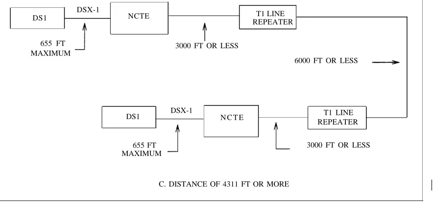
DS1 — TRANSMISSION AND CABLING — Describes cable distance limitations versus cable size, permitted cable types, the DSX-1 interface specification, the need and function of customer service units, on- and off-premises cable configurations, metallic and nonmetallic cable options, and equalizer and compensation settings.
THE DIGITAL LOSS PLAN — Describes transmission loss concepts, the analog and digital loss plans and the differences between them, and the user or installer impact (switch settings and administration values).
ABOUT THIS DOCUMENT xxiii
6.
7.
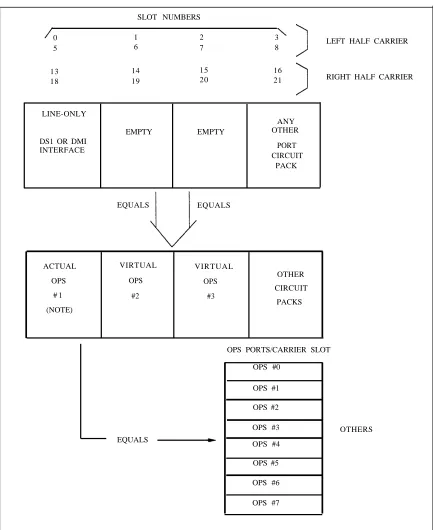
PORT TYPES/INSTALLATION COMPATIBILITIES — Describe the DS1/DMI circuit pack operating modes, slot restrictions, and administration considerations and restrictions. This section also includes a table that lists the available port types and shows their compatibility on a system, release, version, and circuit-pack suffix basis.
ADMINISTRATION OPTIONS AND REQUIREMENTS — Covers the following information: —
—
—
—
Describes those procedures that are required for DS1 services, what the available field encode options are, and the considerations for choosing the options for System 85
Describes those procedures that are required for DS1 services, what the available field encode options are, and the considerations for choosing the options for DEFINITY Generic 2
Describes the administration screens that are required for DS1 services, any unusual or special field requirements or considerations, and options for System 75 and System 75XE
Describes the administration screens that are required for DS1 services, any unusual or special
field requirements or considerations, and options for Generic 1
8. MAINTENANCE AND ALARMS — Describes the diagnostic capabilities and alarms provided
●
●
●
●
by DS1/DMI/ISDN-PRI. This part also provides information on methods of alarm analysis and alarm resolution.
APPENDIXES A.
B.
C.
D.
E.
ADMINISTRATION REQUIREMENTS — Provides screens showing administration field examples for System 75 (R1V2 and R1V3) special-access connections.
SAMPLE INSTALLATION AND MAINTENANCE PROBLEMS — Describes, with examples, some of the more typical field problems, such as translation-based, synchronization-related, and physical-interface connection problems.
ADMINISTRATIVE PROCEDURE SUMMARY — Describes the administrative procedures used on DEFINITY Generic 2 that relate to the ISDN-PRI, including how pertinent administrative fields relate to ISDN-PRI level 3 message contents and general feature operation.
TRUNK TYPE AND SIGNALING TYPE COMPATIBILITY TABLES — Provides tables that define trunk type to signaling type compatibility for System 85 R2V1, R2V2, R2V3, R2V4, and Generic 2.
TIE TRUNK SETTING — Provides administrative settings for tie trunks used with ISDN-PRI.
ABBREVIATIONS GLOSSARY INDEX
NOTE: Although this document applies specifically to DS1/DMI and to ISDN-PRI, the Generic 2
Remote Group Interface (RGI) is also a DS1 application. As such, portions of chapter 1, Introduction, chapter 3, DS1 Transmission and Cabling, chapter 4, The Digital Loss Plan, and chapter 8, Maintenance and Alarms, may also apply in a general sense to the RGI. Specific information on the RGI is provided in documents on that subject.
HOW TO USE THIS DOCUMENT
How you will use this document will depend on several factors such as the amount of training you have received or your personal preferences for working with something new. You may want to read this document from cover to cover, use it merely as a reference when questions arise, or find that something in between these two extremes will best suit your needs. At the very least, you should make sure that you are familiar with how the document is organized and what it contains. This can be accomplished by reading this preface, About this Document, and then carefully scanning the document, taking special note of all headings.
The Table of Contents and the Index are provided for those times when you have problems finding information about a specific topic.
TRADEMARKS AND SERVICE MARKS
●
●
●
●
●
5ESS®, ACCUNET®, Callmaster®, DATAPHONE®, DEFINITY®, DIMENSION® and MEGACOM® are registered trademarks of AT&T.
ESS™ is a trademark of AT&T.
IBM® is a registered trademark of International Business Machines Corporation. MS-DOS® is a registered trademark of Microsoft Corporation.
UNIX® is a registered trademark of UNIX System Laboratories, Inc.
RELATED SOURCES
The following documents may be referenced to obtain additional information on specific subjects. DP2 Channel Service Unit User’s Manual
AT&T DEFINITY® 75/85 Communications System Generic 1 Maintenance
AT&T DEFINITY® 75/85 Communications System Generic 1 and System 75 and System 75 XE Feature Description
AT&T DEFINITY® 75/85 Communications System Generic 2 Administration Procedures
AT&T DEFINITY® 75/85 Communications System Generic 2 Maintenance Procedures
AT&T DEFINITY® 75/85 Communications System Generic 2 Maintenance Repair
Strategies
Network and Data Services Reference
AT&T System 85 Release 2 Version 4 Administration Procedures
999-100-189 555-204-105 555-200-201
555-104-506
555-104-117 555-104-118
ABOUT THIS DOCUMENT xxv
BCM32000 — Description, Installation, and Maintenance — Digital Transmission Systems
Channel Division Multiplexer Installation and Maintenance Manual
Channel Expansion Multiplexer Installation and Maintenance Manual
D4-Channel Bank Channel Units — Application Engineering
DEFINITY® Communications System Generic 1.1 to 4ESS Via ISDN PRI Access
DEFINITY® Communication System Generic 2.1 to Generic 1.1 with DCS
DEFINITY® Communications System Generic 2.1 to 4ESS Via ISDN PRI Access
Digital Multiplexed Interface (DMI) Technical Specification Issue 3.2
ESF T1 Channel Service Unit User Manual
Integrated Services Digital Network (ISDN) Primary Rate Interface for AT&T Communications (Technical Publication 41459)
ISDN-BRI Reference Manual
Performance Quality Analysis
System 85 R2V4 to 4ESS Via ISDN PRI Access
System 85 R2V4 to DEFINITY® Communications System Generic 1.1 via ISDN PRI Access
365-287-100
365-165-101IS 365-160-101IS 855-351-105 555-037-234 555-037-238 555-037-237 555-025-204 999-100-305 326-201
555-025-102 190-404-120 555-037-232 555-037-233
HOW TO MAKE COMMENTS ABOUT THIS DOCUMENT
Reader comment cards are behind the table of contents of this document. While we have tried to make this document fit your needs, we are interested in your suggestions for improving it and urge you to complete and return a reader comment card.
If the reader comment cards have been removed from this document, please send your comments to: AT&T
Technical Publications Department Room 31c32
INTRODUCTION 1-3
ISDN is a collection of international recommendations that are evolving toward adoption as a CCITT telecommunications standard. These recommendations are based on the following objectives:
1. To provide the user with end-to-end digital connectivity (which in theory will be independent of the network provider)
2. To use the end-to-end digital connections as shared (integrated) facilities, thus permitting the same channel to be used alternately for voice, data, or imagery/video
3. To permit users access to these new services by a limited set of multipurpose customer interfaces (each interface being CCITT approved)
The goal is to provide the full set of ISDN services and features on digital customer-premises switches, digital COs, and to provide these services end-to-end through the public digital network.
The CCITT ISDN recommendations define two functionally different types of communication interfaces known as the ISDN primary rate interface (ISDN-PRI) and the ISDN basic rate interface (ISDN-BRI). ISDN-PRI (23B + 1d) recommendations (like DS1) are associated with trunk access, while ISDN-BRI
(2B + 1D) recommendations are associated with line (or user terminal) access.
Initially, the CCITT recommendations were identified by their standardization committee as the "I" series documents (I.412, I.431, I.441, and I.451). Later, another CCITT development committee used the I-series documents to develop another series of documents called the “Q” series (Q.921 or Q.931). Recommendations are designed to be compatible with the Open Systems Interconnection (OSI) 7-layer model. Both ISDN-PRI and ISDN-BRI include recommendations for layers 1, 2, and 3. Recommendations for the PRI are similar in function but not identical to those for the BRI. The BRI and the PRI are compared as follows.
Layer 1 PRI defines functions provided by the physical layer. It requires use of a DS1 and is based on recommendations I.211, I.412, and I.431. These layer 1 functions include the physical connector, the creation of the bit stream by multiplexing the information B-channels and signaling D-channel, the orderly sharing of the D-channel, timing, synchronization, framing, and line coding.
Layer 2 PRI defines the signaling-channel (data-link) protocol (that is, the envelope). This
layer includes the LAPD protocol (the focus of the Q.921 recommendations). The LAPD protocol permits many logical links to be multiplexed into one D-channel. It also provides flow control and error recovery for each logical link.
Layer 3 PRI defines the network-layer protocol (that is, the message), which consists of the
Q.931 recommendations. It provides the methods (messages) to establish, maintain, and terminate network connections between communicating ISDN applications. The message set includes over 200 messages, which provide many services/features that are not available without ISDN. Some of these include:
●
●
●
●
Call establishment messages (alerting, call proceeding, connect, setup) Call information phase messages (resume, suspend)
The BRI terminates at a subscriber’s residence or office. There, it connects either to an ISDN compatible terminal or to a conventional terminal via a terminal adapter. The BRI channel structure consists of a 2B + 1D format. Each B or bearer channel provides a 64K-bps information channel. Each D-channel provides a 16K-bps signaling channel.
NOTE: Specific descriptions for BRI layers 1, 2, and 3 are not included here. Another document
that fully describes ISDN-BRI architecture, specific administration requirements, and service provisioning is being developed. (Refer to ISDN-BRI Reference Manual (555-025-102) for more information.)
When connecting customer-premises switches to the public network, consider the features and services supported on each end of the connection. At the time of this publication, the AT&T public network supported the following services:
●
●
●
●
●
●
ACCUNET® Switched Digital Service
MEGACOM® MEGACOM 800
Call-by-call (CBC) Service Selection Automatic number identification (ANI) Software-Defined Network (SDN)
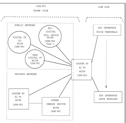
System 85 R2V4 and Generic 1 supports ISDN-PRI but not ISDN-BRI. However, System 85 R2V4 uses the line-side digital communications protocol (DCP) to provide end-to-end digital connectivity. The DCP channel structure consists of 2I + 1S channel format. Each I-channel provides a 64K-bps information (voice/data) channel, while the S-channel provides an 8K-bps signaling channel. The DCP is similar to ISDN-BRI, both in structure and in function. The DCP was AT&T’s early attempt to offer
(what at that time was) the evolving BRI standard. Figure 1-1, System 85 R2V4 ISDN Configuration, shows various trunk-side and line-side connections to a System 85 R2V4.
Generic 1 (R1V5) and Generic 2 provide a signaling method called nonfacility-associated signaling (NFAS). NFAS allows a D-channel on one PRI facility (sometimes called a PRI pipe) to provide signaling for B-channels on this same and other PRI pipes. On a point-to-point basis, all B-channels controlled by a D-channel (called a signaling group in Generic 1 and a D-channel group in Generic 2) must be administered in the same order so the sequence of channel IDs match (that is, the channel IDs of the terminating ISDN facility must match the channel IDs of the originating facility). For example, if two DS1s connect a Generic 1 to a Generic 2 and the Generic 1 lists B-channels 1-23 of the first facility followed by B-channels 1-11 of the second facility in a NFAS signaling group, the Generic 2 must also list in the same order B-channels 1-23 of the first facility followed by B-channels 1-11 of the second facility in its NFAS D-channel group.
Without administering NFAS for a trunk (B-channel), the Interface Identifier octet of the channel-ID IE may be omitted for calls made on that trunk. For example, if an ANN35 is not administered for NFAS, it is a 23B + 1D interface but no channel ID is sent on the D-channel messages for those trunks. If, however, this same interface is administered for NFAS and the D-channel controls the B-channels on the same board, it is still a 23B + 1D board but now the channel ID is sent.
INTRODUCTION 1-5
ISDN-PRI LINE SIDE
TRUNK SIDE
PUBLIC NETWORK
4E11 DCP INTERFACE
DIGITAL VOICE TERMINALS
TOLL OFFICE
DIGITAL FX WITH
CO ISDN-PRI
WITH (Phase 1)
ISDN-PRI
5ESS DIGITAL CO
WITH
ISDN-PRI SYSTEM 85
R2 V4 WITH PRIVATE NETWORK
ISDN-PRI
SYSTEM 85
DCP INTERFACE R2 V4
WITH OTHER DATA MODULES
ISDN-PRI VENDOR SWITCH
WITH ISDN-PRI
Figure 1-1. System 85 R2V4 ISDN Configuration
With NFAS, if two or more PRI pipes are present, an optional D-channel backup feature is available. One D-channel is administered as the primary D-channel on one DS1 and the secondary D-channel on another DS1. Only one D-channel per primary-secondary pair can be active at a time. If the primary D-channel fails, the signaling function is switched automatically to the secondary (sometimes called the backup) D-channel. Without D-channel backup, D-channel failure results in loss of service for all calls passing through a PRI pipe.
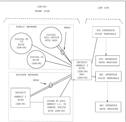
Generic 2 offers ISDN-BRI, however, some BRI capabilities are not initially available. Figure 1-2, Generic 2 ISDN Network Configuration, shows a Generic 2 switch in a sample network.
ISDN-PRI LINE SIDE TRUNK SIDE
PUBLIC NETWORK NFAS
DCP INTERFACE
DIGITAL VOICE TERMINALS
TOLL OFFICE DIGITAL FX
WTIH 4ESS CO
WITH ISDN-PRI
DIGITAL CO
WITH DCP INTERFACE
ISDN-PRI DEFINITY DATA MODULES
GENERIC 2 WITH ISDN-PRI
PRIVATE NETWORK AND BRI INTERFACE
ISDN-PRI VOICE TERMINALS NFAS
DEFINITY GENERIC 2
WITH SYSTEM 85 R2V4,
ISDN-PRI GENERIC 1,2, OR
BRI INTERFACE VENDOR SWITCH
DATA MODULES WITH ISDN-PRI
Figure 1-2. Generic 2 ISDN Network Configuration
Generic 1 and Generic 2 provide PRI but do not support wideband channels. Additionally, ISDN-BRI is not currently supported in Generic 1. However, end-to-end digital connections are permitted via line-side DCP-interface voice terminals and DCP-interface data modules. Figure 1-3, Generic 1 ISDN Network Configuration, shows a Generic 1 in a sample network.
INTRODUCTION 1-21
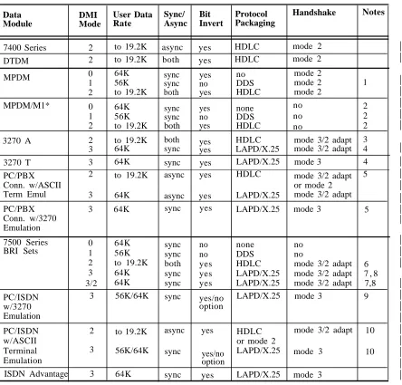
TABLE 1-2. Data Module Capabilities
Data Module DMI Mode User Data Rate Sync/ Async Bit Invert Protocol Packaging Handshake Notes
7400 Series 2 to 19.2K to 19.2K
async yes HDLC mode 2
DTDM 2 both yes HDLC mode 2
MPDM 0 1 2 64K 56K to 19.2K sync sync both yes no yes no DDS HDLC mode 2 mode 2 mode 2 1 MPDM/M1* 0 1 2 64K 56K to 19.2K sync sync both yes no yes none DDS HDLC no no no 2 2 2
3270 A 2
3
to 19.2K 64K
both
sync yesyes
HDLC LAPD/X.25
mode 3/2 adapt mode 3/2 adapt
3 4
3270 T 3 64K sync yes LAPD/X.25 mode 3 4
PC/PBX Conn. w/ASCII Term Emul
2 to 19.2K 64K
async yes HDLC mode 3/2 adapt or mode 2 mode 3/2 adapt
5
3 async yes LAPD/X.25
PC/PBX Conn. w/3270 Emulation
3 64K sync yes LAPD/X.25 mode 3 5
7500 Series
BRI Sets 01 2 3 64K 56K to 19.2K 64K 64K sync sync both sync sync no no yes yes yes none DDS HDLC LAPD/X.25 LAPD/X.25 no no
mode 3/2 adapt mode 3/2 adapt mode 3/2 adapt
6
7 , 8 7,8 3/2
PC/ISDN w/3270 Emulation
3 56K/64K sync yes/no option
LAPD/X.25 mode 3 9
PC/ISDN w/ASCII Terminal Emulation 2 3 to 19.2K 56K/64K
async yes HDLC or mode 2 LAPD/X.25
mode 3/2 adapt 10 sync yes/no option
mode 3 10
ISDN Advantage 3 64K sync yes LAPD/X.25 mode 3 MPDM — modular processor data module
NOTES:
1 .
2.
3.
A mode-2 handshake works only on 64K-bps facilities (such as alternate voice/data or AVD). (Use an MPDM/M1* for mode-1 calls made over robbed-bit facilities.) Since an ISDN-PRI link between a System 85 R2V4 and a Generic 1 uses these facilities, this handshaking will work.
You must use the MPDM/M1* when the far end data circuit-terminating equipment (DCE) is not another AT&T data module or robbed-bit facility (does not do a mode-2 handshake).
Although the MPDM/M1* also suppresses the handshake in mode 2, it is recommended this not be done since rate adaption would not be possible.
"Mode 3/2 adaptive" means that a mode-3 handshake is attempted first. An algorithm is then followed to determine the far-end's mode and either switch to mode 2 or continue in mode 3.
4. 5.
6. 7.
8.
9. 10.
Mode-3 data can only be circuit switched in Generic 1.1 and Generic 2.1. Using mode 3 on a 3270A or 3270T requires a 3270C on the far end.
Mode 2 on the PC/PBX Connection is supported under the ASCII terminal emulation package. The PC/PBX Connection in mode 2 uses a mode 3/2 adaptive handshake if the bit rate is set to 64K. If the rate is set to 19.2K or slower, a mode 2 handshake is used. 3270 emulation on the PC/PBX Connection requires a 3270C data module on the far end. Mode 3 operation is defined as synchronous when in 3270 emulation, otherwise mode 3 operation on the PC/PBX Connection is defined as asynchronous.
Mode 2 on the 7500 series is implemented in the incoming (to the 7500) direction only. Outgoing calls requiring mode 2 speeds use mode 3/2 adaptive BC.
On outgoing mode 3 and mode 3/2 adaptive calls, the 7500 series always inverts bits. On incoming mode 3 and mode 3/2 adaptive calls, the 7500 series checks the restriction bit in the low-layer compatibility IE and either inverts or does not invert depending on the contents of the IE. This is not done for mode 0 calls.
The algorithm used for the mode 3/2 handshake is different for DCP and the 7500 data modules. When called, the 7500 data module starts a mode 3 handshake. If it receives a mode 3 or mode 2 handshake from the calling end within a specified number of seconds, it switches to that mode. If it does not receive a mode 3 or mode 2 handshake within that time, it switches to mode 2. If it does not receive a mode 2 handshake within 15 more seconds, it drops the call.
Options exist on the PC/ISDN Platform with 3270 Emulation to allow the user to choose either 56K-bps or 64K-bps and to choose to invert or not invert bits. The PC/ISDN Platform with 3270 Emulation requires a 3270C data module on the far end.
Options exist on the PC/ISDN Platform with ASCII Terminal Emulation to allow the user to choose either 56K-bps or 64K-bps and to choose to invert or not invert bits. Either mode 3/2 adaptive or mode 2 handshakes are used depending on the baud rate option setting. If the setting is 19.2K-bps or slower, a mode 2 handshake is used. Mode 3 operation is defined as synchronous when in 3270 emulation, otherwise mode 3 operation on the PC/ISDN Platform is defined as asynchronous.
Some applications where DCP and DMI formatted data are not used include the following:
a. When 64K-bps data is transmitted across DS1/DMI/ISDN-PRI facilities (via a dedicated switch connection or DSC) to an endpoint such as a channel bank channel unit.
b. When a point-to-point data application is done with CDMs to drop and insert DS0 channels. Here, it is up to the user endpoints to ensure that the 1s-density requirement is met.
The method used to provide ACCUNET® switched digital service (used by D4-channel banks) also maintains the 1s-density requirement. This method uses only seven of the eight bits for each DS0 channel’s 8-bit word to carry user data. The remaining bit (8) is “wired” to a 1. (MPDM/M1* is compatible with ACCUNET switched digital service).
IMPORTANT CONCEPTS
Important concepts discussed in this section include: ●
●
●
●
●
●
Common-channel signaling Alternate voice/data (AVD) trunks Bearer capability (BC)
ISDN call processing CBC Service Selection
INTRODUCTION 1-23
Common-Channel Signaling
Originally, common-channel signaling (CCS) meant that any of the 24 channels could be used to transmit signaling for the other 23. To offer CCS, both RBS and 24th-channel signaling would have to be disabled to make all 24 channels available to transmit signaling.
Current AT&T applications use only the 24th-channel as the signaling channel and, therefore, the term CCS has been used more and more as a synonym for 24th-channel signaling. Misuse of the term CCS and its original definition have contributed to some misunderstanding. When comparing System 75 and System 85 DS1/DMI administration procedures, you will find that:
a.
b.
The current definition of CCS is used when administering System 75 and Generic 1, although it is 24th-channel signaling that is actually being administered.
The original definition of CCS cannot be administered for System 85 or Generic 2, however, channel signaling can be administered. For Generic 2, the equivalent terms, 23B + 1D or 24th-channel signaling, are used rather than CCS.
Alternate Voice/Data (AVD) Trunks
AVD is an attribute of trunks used with System 85 R2V4 and earlier releases, and System 75 R1V3 and earlier releases, and all Generic 1 switches. For Generic 2, bearer capability, wich identifies the capabilities previously identified with AVD plus many more, is used instead.
AVD relates a trunk group’s translations to the type of signaling required to support the trunk group. From the software perspective (and when applicable), a trunk group is administered for either AVD or voice. Trunk groups administered for AVD may be used for both voice and digital data applications and require a DS1 that is administered for 24th-channel signaling.
Bearer Capability (BC)
System 85 R2V4 introduced the administration attribute known as bearer capability (BC). The primary function of BC is to specify the transport mode and the channel requirements (clear/restricted) needed for completing a data call. BC is used for determing compatibility when non-ISDN facilities are connected to ISDN facilities, including originated calls, terminated calls, and tandem connections. BC must be administered for all trunk groups, every extension's class-of-service (COS), and all Automatic Route Selection (ARS) routing-pattern preferences.
System 85 R2V4
For System 85 R2V4, there are the five different BC codes:
0 Voice and voice-grade data — should be administered for DCP voice extensions, analog lines, analog trunks, and data applications that use modems.
NOTE: Except for 56K-bps, the trunk attribute AVD indicates 24th-channel signaling and
whether a modem pool must be inserted to complete the call.
1
2
3
4
Mode-1 data — with the 56K-bps option — should be administered for 56K-bps synchronous data applications. MPDM uses mode-2 handshake unless using MPDM/M1*.
NOTE: The appropriate data module must be installed and optioned for 56K-bps operation.
This arrangement can be used to support the special format required to support ACCUNET switched digital service or 56K-bps basic service (if using MPDM/M1*).
Mode-2 data — for data modules and EIA data terminations that do not operate as packet-mode data and are optioned for the following data rates: low, 300, 1200, 2400, 4800, 9600, 19.2K-bps. When appropriate, end points that route to DS1/DMI/ISDN-PRI preferences should be administered for mode 2 data. Data modules invert the data and uses mode-2 handshaking.
Mode-3 data — end points should be administered for preferences that are used for packet mode data. DCP inverts the data and uses mode-3/2 handshaking. This is used for patterns associated with ISDN-BRI or PC-PBX.
Mode-0 data — end points should be administered for digital endpoints that are used to transmit
* 64K-bps data.
Depending on the administered value, an originated call will either require an ISDN channel, have an administered preference that an ISDN channel be used, or have no requirement for what type of facility is used to complete the call. For terminated calls and tandem connections, the BC class (BCC) for both links must be compatible. For example, voice and voice-grade data are equivalent to the no requirement case since the call characteristics for all other types of facilities are satisfactory. In contrast, B-channels transmitting 64K-bps digital data require that the connected channel have the same call characteristics (the same BCC) such as where an ISDN channel is required. This information appears in the traveling class mark (TCM) IE (layer 3) codeset 7 in System 85 R2V4, and in codeset 6 in Generic 2.
Generic 1
For information about how BC is done for Generic 1, refer to the AT&T DEFINITY 75/85 Communications System Generic 1 and System 75 and System 75 XE Feature Description (555-200-201).
Generic 2
Generic 2 continues the bearer capability concept with bearer capability class of service, (BCCOS). BCCOS is a set of attributes that is assigned to extensions, AAR and ARS routing pattern preferences, and trunk groups (BCC is one of these attributes). BCCOS determines such actions as call routing and modem pooling insertion based on the calling and called parties BCCs and information types (that is, clear or restricted).
You can assign up to 256 BCCOSs (0-255), where codes 0 through 9 are predefined as:
0
1
2
Voice only — used for voice application extensions (such as DCP and ISDN-BRI extensions, analog lines, and analog trunks)
Mode 2 data — used for EIA data terminations, and DCP or BRI data modules that do not operate as packet mode data and are optioned for any of the following data rates: low, 300, 1200, 2400, 4800, 9600, or 19.2K-bps
Mode 3/2 adaptive data — used for data applications that can run both modes 3 and 2 (such as BRI, PC/PBX, and 3270 data modules). Mode 3 is tried first; if it fails, mode 2 is used.
INTRODUCTION 1-25
3
4
5
6
7
8
9
Unknown digital — used for those calls of any mode (0-3) where the signaling message does not specify a mode (such as DS1 trunks using common-channel or 24th-channel signaling)
Unkown analog — used for voice or voice-grade data calls where the signaling message does not specify a type (such as analog trunks and robbed-bit DS1 trunks)
Voice-grade data — used for data applications that use modems
Mode-0 data — used for facilities that transmit 64K-bps data (DCP and BRI extensions, DMI-BOS trunks, and ISDN-PRI facilities).
Mode-1 data — used for 56K-bps synchronous data applications. The appropriate data module must be installed and optioned for 56K-bps operation.
NOTE: This arrangement can be used to support the special format required for ACCUNET
switched digital service or 56K-bps basic service. DCP uses a mode-2 handshake unless an MPDM/M1* data module is used.
Mode-3 data — should be administered for those applications requiring packet mode data. X.25 — X.25 is administered only for DCIU and other X.25 links.
Predefined BCCOSs should not be redefined. Lines, trunks, and AAR/ARS preferences are assigned the default BC when one is not administered. Generic 2 BCCOS defaults are intended to make a Generic 2 switch operate like a System 85 R2V4 (that is, Generic 2 will insert modem pool members and block calls.) Table 1-3, Bearer Capability Class of Service, lists the default values for common switch parameters.
TABLE 1-3. BCCOS
Switch Parameter Default Value
Analog Lines
All trunks except Host Access AAR/ARS Preferences Host Access trunks
DCP data modules (both lines and trunks) BRI extensions
0 0 0 1 1 0
NOTE: Extensions with multiple appearances must have the
same BC administered for each appearance. BCCOS is implemented by doing the following five steps:
Define a BCCOS in procedure 014, word 1
Fields 2-16 of this procedure determine how the extension, preference, or trunk group assigned a BCCOS will treat calls made to that extension, preference, or trunk group. This treatment is based on the BC and information type fields of the BCCOS of the calling extension or trunk.
Assign a BCCOS to extensions in procedure 000, word 3
Field 1 assigns a BCCOS to an extension number. This assignment affects the pattern or preference selected for this extension on outgoing calls (see step 4 below).
1.
2.
3. 4. 5.
The 10 BCs are defined in field 16 of procedure 014, word 1. This definition codes the BC IE in the setup message when the extension (entered in field 1 of procedure 000, word 3) accesses an ISDN-PRI trunk for an outgoing call (DCP only).
When a Generic 2 is connected to a 4ESS, assign a network-specific facility (NSF) in procedure 279, word 1
Each interexchange carrier (which provides public network ISDN service) must have a unique identifier number. Furthermore, each carrier may provide multiple ISDN services and ISDN features that must be individually identified via a Network Specific Facility (NSF) coding value. A NSF is an ISDN IE (sent in the setup message) that is used to identify the network or feature associated with the call. When connected to a 4ESS, a Generic 2 must send the appropriate NSF for MEGACOM, SDN, and ACCUNET switched digital service calls. (MEGACOM 800 service calls do not require an NSF since it is an incoming-only service and the Generic 2 cannot tandem it to another switch as a MEGACOM 800 call.)
Assign AAR and ARS routing preferences in procedures 309, word 5, and 321, word 5 Assign the same NSF index from field 1 of procedure 279, word 1, in field 5 of both of these procedures.
For procedure 309, word 5, the value entered in field 5 along with the value entered in field 12 of procedure 309, word 1, (the IXC/ISDN network identifier) determine the NSF IE for calls routed over this ARS plan, pattern, or preference. An NSF IE is not sent if a value is not entered. If field 5 has no value but an IXC/ISDN network identifier is specified, the network identification is specified with the transit network selection IE instead of the network-specific facilities IE.
For procedure 321, word 5, the fields in this procedure define for AAR patterns and preferences what procedure 309, word 5, define for ARS plans, patterns, and preferences.
Administer trunk groups in procedure 100, words 1-3 For procedure 100, word 1:
Field 6 defines the trunk type of a specific trunk group. For ISDN trunk groups as well as other types of trunk groups, the entered type defines feature operation for the trunk group. For example, if a trunk group is assigned the type of 19, incoming calls over this trunk group are routed to the attendant console. On Direct Inward Dial (DID) trunk-type groups, the switch expects station-number digits on all incoming trunks; on tie-trunk-type groups, the switch can handle either station-number digits or network numbers.
For an ISDN trunk group, a dynamic trunk type (120) can be assigned to the group. This trunk type allows the group to process calls with a different trunk type on a call-by-call (CBC) basis. For example, one incoming call over the group may expect station number digits (such as a MEGACOM call), while the next call over the group may expect a network number (such as a Software Defined Network call, also called a SDN call). The ISDN Dynamic trunk type allows administration of both an AAR/ARS prefix digit (procedure 103) and a DID additional digit (procedure 101). (This cannot be done for any other type of trunk group.)
INTRODUCTION 1-27
For procedure 100, word 2:
Field 1 specifies the trunk group number and field 2 specifies a BCCOS number for this trunk group. For interworked tandem calls through the switch where the calling trunk is not ISDN-PRI trunk and the called trunk is, the BCCOS of the non-ISDN-PRI trunk is used to define a BC for the outgoing setup message over the ISDN-PRI trunk. This COS also defines other routing parameters.
For procedure 100, word 3:
Field 2 assigns a trunk group as ISDN-PRI that has ISDN-PRI signaling (type 20). This causes ISDN-PRI message-oriented signaling (MOS) to occur for the trunk group.
Field 8 prevents the sending of various IEs over the trunk group specified in field 1.
For specific information on routing rules, refer to appendix C: Administrative Procedure Summary. For specific information on administering a Generic 2 to a 4ESS, see DEFINITY Communications System Generic 2.1 to 4ESS Via ISDN PRI Access, 555-037-237.
For specific information on proper implementation of BCCOS, refer to DEFINITY® Communications System Generic 2 Administration Procedures, 555-104-506.
ISDN Call Processing
ISDN-PRI is a trunk signaling type. ISDN trunk signaling is applied on a per-trunk-group basis and is compatible with most existing switch features. ISDN trunk signaling also supports many new networking features as described next.
Outgoing Calls
For outgoing calls, ISDN trunk groups may be categorized as those that: 1.
2. 3.
Require that address digits be collected before trunk seizure (this can be done on non-ISDN trunks)
Seize the trunk and do not outpulse any digits (this is called digit sending)
Seize the trunk, obtain a start dial signal, and then begin digit outpulsing (this is called cut-through dialing) to the terminating switch
Each call routed to an ISDN signaling trunk group generates a series of Q.931 messages over the D-channel. For example, the calling party IE of the ISDN-PRI setup message assembles the dialed digits as ASCII numbers that correspond to the defined numbering-plan format. Also included within the setup message are the BC requirements, B-channel identification, and network-specific facilities (NSF). If the requested facilities are not available, either channel negotiation is begun or, if appropriate, a cause failure code is returned and the call attempt is dropped. Otherwise, the called switch responds with a call proceeding or alerting message.
Incoming Calls
Incoming ISDN calls are generally processed similar to outgoing ISDN calls. Initially, the called switch receives a setup message over the D-channel and processes the contents of the setup message. The call states of the switch, how the particular trunk groups are administered, and decisions taken as a result of
processing the setup message will determine exactly how the ISDN call is processed.
Look-Ahead Interflow
Look-Ahead Interflow allows customers with multiple ISDN-PRI locations to achieve optimum call-handling capability and agent productivity by routing calls among call centers as though they were one location. Look-Ahead Interflow is normally used with the Automatic Call Distribution (ACD), AAR/ARS, and Call Vectoring features to conditionally select a distant switch to handle interflowed calls. Which distant switch the sending switch selects is determined by a series of “route to” steps within the same vector. Look-Ahead Interflow then lets the sending switch use the D-channel to query the status of a distant switch before sending the call. If the distant switch can handle the interflow call, it accepts the call with a D-channel (progress) message and the call is sent over the B-channel. If the distant switch cannot handle the call, it rejects the call with a different (disconnect) message. The sending switch then either selects an alternative distant switch from subsequent “route to” steps and sets up another status query, or invokes the alternative action program within its own local vector. Calls can be intelligently interflowed among switches based on (that is, progress of the message):
● Time of oldest call in the queue ● Number of calls in the queue
● Number of staff or available agents to handle calls ● Time of day
NOTE: Look-Ahead Interflow currently works only in private network configurations.
NOTE: Call Vectoring and AAR/ARS must be present for Look-Ahead Interflow to work properly.
Summary
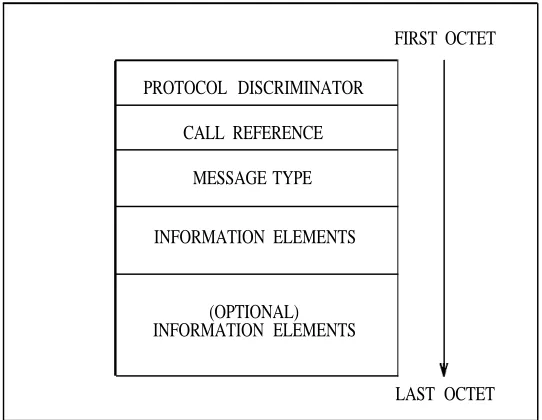
ISDN calls are processed using conventional, well-established, time-proven call-processing techniques. The ISDN layer-3 software maintains status records for the ISDN call states, maintains the call-reference value (CRV) for each B-channel, and starts sending messages. To request services from the conventional call-processing routines, ISDN layer-3 software informs the switch of items such as incoming calls and dialed digits.
INTRODUCTION 1-29
The ISDN-PRI level-3 messages are a collection of IEs that are defined in the Q.931