AT&T
PARTNER™ Plus
Communications System
Copyright © 1990 AT&T
All Rights Reserved
Printed in U.S.A.
AT&T 999-506-141
Issue 2
October 1990
Notice
Every effort was made to ensure that the information in this document was complete and accurate at the time of printing. However, information is subject to change.
Federal Communications Commission (FCC) Information
For important FCC interference, registration, and repair information, see appendix C of this document.
Trademarks
PARTNER is a trademark of AT&T.
MAGIC-ON-HOLD is a registered trademark of AT&T. MLS-6, MLS-12, and MLS-12D are trademarks of AT&T. SYSTIMAX is a trademark of AT&T.
Warranty
AT&T provides a limited warranty to this product. Refer to “AT&T Limited Warranty and Limitation of Liability” in chapter 9 of the System Manager's Guide.
Ordering Information
The order number for this book is 999-506-141. To order copies of this document, call 1 800 432-6600 in the U.S. or 1 800 255-1242 in Canada. For more information on how to order this and other PARTNERTM
Plus system reference materials, refer to “Reference Materials” in the Introduction. For information on ordering replacement parts, accessories, and other compatible equipment, refer to the System Manager's Guide, appendix B.
Support Telephone Numbers
AT&T provides a toll-free customer helpline 24 hours a day. In the U.S. call the AT&T Helpline at 1 800 628-2888 if you need assistance when installing, programming, or using your system. In Canada call one of the following Technical Assistance Centers for service or technical assistance:
Eastern Canada and Ottawa: 1 800 363-1882
Ontario: 1 800 387-4268
Contents
About This Guide
1
System Components and Specifications
■ Hardware
■ An Example System Setup ■ Specifications
1-1 1-2 1-4
2
Installing the Hardware
General Guidelines Installing the Control Unit
Installing Telephones and Other Equipment Removing/Replacing Modules
2-1 2-2 2-4 2-6
3
System Programming
■ Overview
■ General Instructions ■ Programming Procedures
4
Centralized Telephone Programming
■ Overview
■ Programming Procedures
3-1 3-3 3-4
A
Programming for Operation Behind PBX or Centrex
B
Dialing Restrictions Summary
C
FCC Information
About This Guide
The PARTNERTM
Plus Communications System is friendly and easy-to-use. Its digital technology provides features that give busy, growing businesses an advantage in today’s marketplace.
The system is easy to install and program. As your business grows, you can expand the system and reprogram it with little effort and disruption. This Installation and Programming Guide is a comprehensive guide to setting up the PARTNER Plus system. Step-by-step instructions help you install, expand, and program the system. A companion book, the System Manager’s Guide, tells you how to use the system’s features and how to customize individual telephones.
How to Use This Guide
■
■
■
■
■
Product Safety Labels
If you are installing the system for the first time, we suggest you read this guide completely. Chapter 1 is an overview of the system, while the other chapters give specific information on installation and programming.
If you are installing additional equipment, see chapter 2, “Installing the System,” chapter 3, “System Programming,” and chapter 4, “Centralized Telephone Programming.”
If you need to reprogram the system, see chapter 3, “System Programming.”
If you need to reprogram telephones, see chapter 4, “Centralized Telephone Programming.”
If you are connecting the PARTNER Plus system to a PBX or Centrex, see appendix A, “Programming for Operation Behind PBX or Centrex.”
If you need information on calling restrictions, see appendix B, “Dialing Restrictions Summary.”
This book contains several product safety labels, identified by a A CAUTION label indicates the presence of a hazard that will or can cause property damage or minor personal injury if the hazard is not avoided.
Reference Materials
The following materials are available to help you install, program, and use the PARTNER Plus system (the order numbers are in parentheses):
System Planner provides the forms needed to plan and record how your sys-tem and telephones are to be programmed. If you need a Syssys-tem Planner, contact your AT&T customer service representative or authorized dealer.
Installation and Programming Guide (999-506-141) provides instructions for installing the hardware and programming the system.
System Manager’s Guide (999-506-142) provides instructions for using the system and its features.
Quick Reference for Users with MLS-Model Telephones (999-506-145, pack-age of 6) contain basic instructions for using MLS-model phones with the PARTNER Plus system.
To order additional reference materials (except the System Planner, call the AT&T Customer Information Center:
In the U. S.: 1 800 432-6600
In Canada: 1 800 255-1242
How to Comment on This Guide
A feedback form is located at the end of this guide, after the appendices. If the feedback form is missing, send your comments and recommendations for changes to:
A. Sherwood
AT&T General Business Systems 99 Jefferson Road (Room 2B-63) Parsippany, NJ 07054
Fax: 201 887-6898
System Components
and Specifications
1
Hardware
The PARTNER Plus system’s modular hardware design makes it easy to install and expand. The main system component is the control unit, to which you connect telephones and other equipment.
Control Unit
The control unit includes:
■ Processor Module. The processor module contains the software that controls the system’s features. It also has two jacks for connecting a loudspeaker paging system and an audio source for music on hold.
■ 206 Modules. Phone lines, phones, and other equipment connect to the modular jacks on 206 modules. Each module has jacks for 2 lines and 6 extensions. A system can have up to four 206 modules for a maximum of 8 lines and 24 extensions. The system requires at least one 206 module (purchased separately).
■ Backplane. All the modules slide easily into the backplane, which channels power to the system.
■ Cover. The cover slides onto the front of the backplane.
PARTNER TeIephones
Other Equipment
When connecting standard equipment to the PARTNER Plus system, the total ringer equivalence number (REN) of the device(s) connected to each 206 extension jack cannot exceed 2. The REN is listed on a label on the device.
AT&T manufactures three Multi-Line Series (MLS) telephones specifically designed to work with your PARTNER Plus system:
■ Model MLS-12DTM
for up to 8 outside lines, has 12 buttons with dual lights, 6 buttons without lights, a built-in speaker and microphone, and a display. We refer to this phone as the PARTNER display phone.
■ Model MLS-12™ is the same as model MLS-12D without the display. We refer to this phone as the PARTNER 12-button phone.
■ Model MLS-6TM
for up to 4 outside lines, has 6 buttons with dual lights and a built-in speaker. We refer to this phone as the PARTNER 6-button phone.
The system can have any combination of these phones, but extension 10 must have a PARTNER display phone, for system programming.
The PARTNER PIUS system also works with industry-standard
telecommunica-tions equipment. You can connect equipment such as standard, single-line touch-tone or rotary phones, fax and answering machines, modems, and door-phones to the system—without expensive adapters or additional phone lines.
You can connect a standard device to an extension jack by itself or combined with another device. For example, you can connect a phone and an answering machine to one extension by using an AT&T 267F2 bridging adapter (two included with each 206 module).
An Example System Setup
This PARTNER Plus System has 4 outside lines and 8 extensions connected to a variety of PARTNER phones and other equipment. The boldface numbers refer to the following list which gives a brief description of the system’s hardware components.
Control Unit. The heart of the PARTNER Plus system, the control unit consists of a backplane, cover (not shown), one processor module, plus up to four 206 modules. The backplane channels power to the system and connects the incoming telephone lines to the system.
Processor Module. The processor module contains the electronics that provide most of the system features. It also has audio and paging jacks.
Page Jack. The loudspeaker paging system plugs directly to this modular jack.
Music-On-Hold Jack. The audio source plugs directly into this RCA jack.
206 Module. Each 206 module has jacks for 2 incoming telephone lines and 6 extensions. The system can have up to four 206 modules.
Line Jacks. Outside telephone lines connect to the top 2 jacks on each 206 module.
Extension Jacks. Telephones and other telecommunica-tions equipment connect to the bottom 6 jacks on the 206
modules.
AC Power. An ordinary 110 VAC grounded wall outlet (not controlled by an on/off switch) supplies power to the control unit.
Network Interface Jacks. Incoming telephone lines service the system through these jacks. These lines can be from the local telephone company or another system, such as a PBX (Private Branch Exchange) or Centrex.
PARTNER Display Phone: Extension 10. The system operator in this example is the receptionist on extension 10 and has a PARTNER display phone. This phone can handle 8 outside lines and has a display showing the time, number dialed, duration of call, and programming messages. Also, its programmable buttons (two with lights) can be programmed to store additional features and Auto Dial numbers. Because the display is required for system programming, extension 10 on your system must also have an PARTNER display phone.
Standard Touch-Tone Telephone Used as a Power FailureTeIephone. In a power failure, the first extension jack on each 206 module connects to the first outside line on that module to provide continuous service to standard non-PARTNER telephones. In this example system, the PARTNER phone on extension 10 will not work during a power failure. However, the receptionist can use the standard touch-tone phone connected to extension 10 to place and receive calls on line 1.
AT&T 267F2 Bridging Adapter. This adapter com-bines the standard touch-tone phone and the PARTNER display phone on one extension jack. The adapter has two modular jacks, one for each phone. You can use the bridging adapter to combine any two devices (PARTNER telephones, industry-standard telephones, or other equip-ment) on one extension jack as long as the total Ringer Equivalence Number on each extension jack is 2 or less. (A device’s Ringer Equivalence Number—REN--is shown on its UL label.) The bridging adapter plugs into a wall jack or directly into an extension jack on the 206 module.
PARTNER 12-Button Phone. This phone is Iike the PARTNER display phone, but it has no display.
PARTNER 6-Button Phone and Answering Machine. Using a 267F2 bridging adapter, both a PARTNER 6-button phone and an answering machine are connected to one extension. The PARTNER 6-button phone accommodates up to 4 outside lines.
Industry-Standard Telephone. A standard single-line touch-tone phone (such as you might have in your home) is connected directly to the extension jack.
Doorphone. A doorphone is installed at the entrance. When someone at the entrance presses the button on the doorphone, up to 5 designated telephones in the office ring automatically.
Bell. A loud bell connected directly to the extension jack rings when the extension is called.
Fax Machine and Standard Telephone. A fax machine and standard touch-tone phone are connected together on an extension jack. This setup lets you share the fax line with a telephone. If you pick up the phone and hear a fax signal, you can simply hang up to let the fax machine receive the call.
Alternatively, you can use a PARTNER phone at another extension to monitor the fax machine (“Fax Management”). To do so, first use System Programming to identify the fax machine extension. Then program a lighted button on a PARTNER phone with the fax extension number as an Auto Dial number. You can then use the Auto Dial number to quickly transfer calls from that extension to the fax machine.
In addition, the light on that button shows whether the fax machine is in use, busy, returning a call you transferred to it, or not answering calls. If your AT&T fax machine includes the “Notify” feature, the fax machine can also notify you when a fax has been received.
Modem. A modem connected directly to an extension jack provides data communications capability to the personal computer.
Loudspeaker Paging System. A paging system is connected to the modular PAGE jack on the processor module. The PARTNER Plus system is compatible with AT&T’s paging systems.
Music-On-Hold Source. AT&T’s MAGIC-ON-HOLD®
cassette deck is connected to the RCA jack on the proces-sor module to provide customized music and messages for callers on hold. For information on MAGIC-ON-HOLD, call your AT&T representative or the AT&T Sourcebook at 1 800 451-2100. You can connect any type of audio equipment to your system (including a CD player, casette player, stereo receiver, etc.), but you must supply an audio cord with an RCA plug.
NOTE: Users of equipment that rebroadcasts copyrighted music or other material may be required to obtain a license from a third party such as ASCAP or BMI.
Specifications
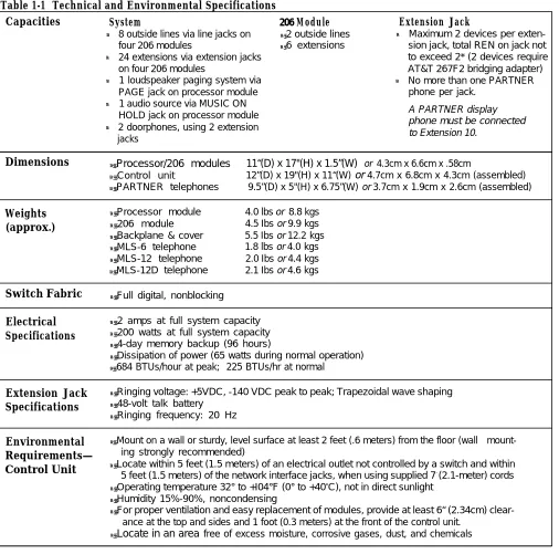
ATable 1-1 Technical and Environmental Specifications
Capacities System 206 Module Extension Jack
●
●
●
●
●
8 outside lines via line jacks on ● 2 outside lines ●
four 206 modules ● 6 extensions
24 extensions via extension jacks on four 206 modules
1 loudspeaker paging system via ●
PAGE jack on processor module 1 audio source via MUSIC ON HOLD jack on processor module 2 doorphones, using 2 extension jacks
Maximum 2 devices per exten-sion jack, total REN on jack not to exceed 2* (2 devices require AT&T 267F2 bridging adapter) No more than one PARTNER phone per jack.
A PARTNER display phone must be connected to Extension 10.
Dimensions ● Processor/206 modules 11“(D) x 17"(H) x 1.5”(W) or 4.3cm x 6.6cm x .58cm
● Control unit 12”(D) x 19"(H) x 11“(W) or 4.7cm x 6.8cm x 4.3cm (assembled)
● PARTNER telephones 9.5”(D) x 5"(H) x 6.75”(W) or 3.7cm x 1.9cm x 2.6cm (assembled)
Weights ● Processor module 4.0 lbs or 8.8 kgs (approx.) ● 206 module 4.5 Ibs or 9.9 kgs
● Backplane & cover 5.5 Ibs or 12.2 kgs
● MLS-6 telephone 1.8 lbs or 4.0 kgs
● MLS-12 telephone 2.0 Ibs or 4.4 kgs
● MLS-12D telephone 2.1 Ibs or 4.6 kgs
Switch Fabric ● Full digital, nonblocking
Electrical ● 2 amps at full system capacity Specifications ● 200 watts at full system capacity
● 4-day memory backup (96 hours)
● Dissipation of power (65 watts during normal operation)
● 684 BTUs/hour at peak; 225 BTUs/hr at normal
Extension Jack ● Ringing voltage: +5VDC, -140 VDC peak to peak; Trapezoidal wave shaping Specifications ● 48-volt talk battery
● Ringing frequency: 20 Hz
Environmental ● Mount on a wall or sturdy, level surface at least 2 feet (.6 meters) from the floor (wall mount-Requirements— ing strongly recommended)
Control Unit ● Locate within 5 feet (1.5 meters) of an electrical outlet not controlled by a switch and within
5 feet (1.5 meters) of the network interface jacks, when using supplied 7-
(2.1-meter) cords
● Operating temperature 32° to +I04°F (0° to +40
o
C), not in direct sunlight
● Humidity 15%-90%, noncondensing
● For proper ventilation and easy replacement of modules, provide at least 6“ (2.34cm)
clear-ance at the top and sides and 1 foot (0.3 meters) at the front of the control unit.
● Locate in an area free of excess moisture, corrosive gases, dust, and chemicals
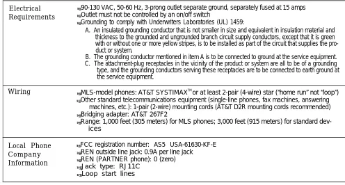
Table 1-1 Technical and Environmental Specifications (cont.)
Electrical ● 90-130 VAC, 50-60 Hz, 3-prong outlet separate ground, separately fused at 15 amps Requirements ● Outlet must not be controlled by an on/off switch
● Grounding to comply with Underwriters Laboratories (UL) 1459:
A. An insulated grounding conductor that is not smaller in size and equivalent in insulation material and thickness to the grounded and ungrounded branch circuit supply conductors, except that it is green with or without one or more yellow stripes, is to be installed as part of the circuit that supplies the pro-duct or system.
B. The grounding conductor mentioned in item A is to be connected to ground at the service equipment. C. The attachment-plug receptacles in the vicinity of the product or system are all to be of a grounding
type, and the grounding conductors serving these receptacles are to be connected to earth ground at the service equipment.
Wiring ● MLS-model phones: AT&T SYSTIMAX TM
or at least 2-pair (4-wire) star (“home run” not “loop”)
● Other standard telecommunications equipment (single-line phones, fax machines, answering
machines, etc.): 1-pair (2-wire) mounting cords (AT&T D2R mounting cords recommended)
● Bridging adapter: AT&T 267F2
● Range: 1,000 feet (305 meters) for MLS phones; 3,000 feet (915 meters) for standard
dev-ices
Local Phone ● FCC registration number: AS5 USA-61630-KF-E Company ● REN outside line jack: 0.9A per line jack
Information ● REN (PARTNER phone): 0 (zero) ● Jack type: RJ11C
● Loop start lines
Installing the Hardware
General Guidelines
Instructions for installing the control unit, telephones, and other equipment are on the following pages (figures 2-1 to 2-3). Before you begin, please note the following guidelines:
If you combine a standard phone and PARTNER phone on one extension, you may want to turn off the ringer of the standard phone during normal use.
Using the System Planner is essential for knowing where phones and other equipment are to be installed, and how the system and phones are to be programmed.
Install the control unit so that it meets the environmental and electrical requirements listed on p. 1-4.
If wall mounting the control unit, you will need four #12 screws appropriate for the type of wall and weight of the control unit.
When connecting wires to the jacks on a 206 module, leave at least 2 feet of slack for removing the module without first disconnecting the wires. If you later replace the module, you can remove the old module with the wires in place and plug them into the new module one at a time.
PARTNER phones require at least 2-pair wiring and are compatible with AT&T 4-pair PDS wiring.
Standard phones and other equipment require 1-pair mounting cords (AT&T D2R mounting cords recommended).
When connecting two devices to a single extension, use only an AT&T 267F2 bridging adapter.
Connect a PARTNER display phone to extension 10 for system programming.
Do not connect doorphones to extensions 10, 16, 22, or 28.
Do not install telephones out of the building.
A hotline phone must be a standard, single-line phone, not a PARTNER telephone. However, the hotline phone can ring any type of phone.
During a power outage, neither the system’s features nor PARTNER phones work. However, standard, single-line touch-tone or rotary phones connected to extensions 10, 16, 22, and/or 28 can be used to place and receive calls. These extensions connect directly to lines 1, 3, 5, and 7, respectively. To prepare for a power failure, AT&T recommends:
■ Store standard phones close to extensions 10, 16, 22, and/or 28. During
a power failure, replace the PARTNER phone with the standard phone. Or, connect a standard phone to these extensions at all times, either by itself or combined with an PARTNER phone via a 267F2 bridging adapter.
■ Do not program a Hotline on extension 10, 16, 22, or 28 to keep these
extensions available for power failure use.
If upgrading from a one-module PARTNER system, remove the rubber feet that may be attached to the 206 module before installing.
If upgrading from a two-module PARTNER system, remove the module connector from the the two modules.
Installing the Control Unit
CAUTION: To prevent electrostatic discharge, overheat-ing, or other damage, environmental and electrical condi-tions must meet the specificacondi-tions on p. 1-4.
MOUNT THE BACKPLANE ON A WALL
Hold the backplane in place on the wall. Using the four screw keyholes in the backplane as a template, mark the screw locations on the wall.
Start the four #12 screws, Ieaving thereabout 1/4” out from the wall. Use screws appropriate for the wall surface-when loaded with five modules, the control unit weighs 37.5 pounds.
Slip the backplane onto the screws and tighten them.
INSERT THE MODULES
CAUTION: Do not connect AC power cord before inserting modules.
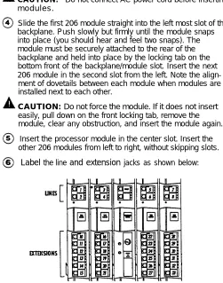
Slide the first 206 module straight into the left most slot of the backplane. Push slowly but firmly until the module snaps into place (you should hear and feel two snaps). The module must be securely attached to the rear of the backplane and held into place by the locking tab on the bottom front of the backplane/module slot. Insert the next 206 module in the second slot from the left. Note the align-ment of dovetails between each module when modules are installed next to each other.
CAUTION: Do not force the module. If it does not insert easily, pull down on the front locking tab, remove the module, clear any obstruction, and insert the module again.
Insert the processor module in the center slot. Insert the other 206 modules from left to right, without skipping slots.
Label the line and extension jacks as shown below:
CONNECT THE OUTSIDE TELEPHONE LINE CORDS
Test for dial tone at the network interface jacks before connecting outside lines.
Connect the outside telephone line cords to the line jacks on the 206 modules, starting with the top line jack on the leftmost 206 module. Route the cords alongside the tele-phone cords. Leave at least 2 feet of slack in the cords so that you can easily reconnect the cords during replacement. Connect the free end of each line cord to the appropriate network interface jacks.
TEST THE SYSTEM
Connect the AC power cord to the power jack on the top right rear of the backplane. Press firmly until it locks into place. Make sure the circuit breakers on each module and the backplane are pushed in.
Plug the other end of the power cord into a grounded 3-prong wall outlet not controlled by a switch.
Check all green lights on the front of the unit. If any lights are out, remove the power cord and reseat the module.
To test the lines, plug a PARTNER 12-button phone into extension 10. Press the line button for each outside line and listen for dial tone. Repeat for extensions 16, 22, and 28.
Disconnect the power cord before continuing.
CONNECT THE MODULAR TELEPHONE CORDS
Connect the modular telephone cords from the telephones to the extension jacks on the 206 modules, starting with the top extension jack on the leftmost 206 module. Route the cords through the hook on the front of the module, then through the slot between the module and the base of the backplane. Leave at least 2 feet of slack in the cords so that you can easily reconnect the cords during replacement.
CONNECT THE MUSIC-ON-HOLD SOURCE (OPTIONAL)
Follow these steps to connect the audio source to the control unit. (Assemble and use according to the manufacturer’s directions.)
Using a flathead screwdriver, turn the volume control on the processor counterclockwise to the lowest setting.
Insert the RCA plug into the RCA jack on the processor (labeled MUSIC ON HOLD). Route the cord through the hook on the front of the module and the slot between the module and the base of the backplane.
Connect the cord to the music-on-hold source according to the manufacturer’s directions. Finally, adjust the volume using the volume control on the processor. Place a call on hold and listen to the level while adjusting. If you do not hear
music at any volume setting, check system programming procedure #602 (chapter 3).
CONNECT THE LOUDSPEAKER PAGING SYSTEM (OPTIONAL)
Only the steps for connection to the control unit are included here. Follow the rnanufacturer's directions for setting up and using it.
Insert the modular plug for the paging system into the modular jack labeled PAGE on the processor. Route the cord as described in step 16.
Connect the cord to the loudspeaker paging system accord-ing to the manufacturer’s directions.
CONNECT THE AC POWER CORD
Connect the power cord as described in steps 9, 10, and 11.
INSTALL THE OUTSIDE COVER
Holding the sides of the cover, slide the cover onto the front of the modules until it meets the backplane.
Installing Telephones and Other Equipment
CAUTION: PARTNER phones must be connected with a 2-pair telephone wire. Other equipment must be connected with a 1-pair mounting cord (AT&T D2R mounting cords recommended).
DESK MOUNTING A PARTNER PHONE
Plug one end of the handset cord into the jack on the handset. Plug the other end of the cord into the small jack on the left side of the base.
Plug one end of the telephone mounting cord into the big jack on the base of the phone. Push the cord in place along the channel on the base of the telephone.
If you want to raise the angle of the phone, install the telephone stand. To attach the stand to the base of the phone, gently place the phone upside down with the low end of the phone to your right. Insert the tab on the narrow end of the stand into the right slot on the base of the phone. Then insert the other tab into the left slot, pushing the stand down and slightly inward until the tab locks into place.
Plug the other end of the mounting cord into the modular wall jack.
Test the intercom. Lift the handset, then press an [Intercom] button. You should hear an intercom dial tone. If not see chapter 8, in the System Manager’s Guide (“Phone Has Lights but No Dial Tone”).
TE
To t
1 2
3
Test the outside line connection. I-M the handset and press an outside line button. You should hear an outside dial tone. If not, see chapter 8, in the System Manager’s Guide (“Phone Has Lights but No Dial Tone").
Slide theQuick Reference card under the telephone.
Label the button sheet and insert as follows:
1 Remove the clear plastic cover from the phone--gently press down on the center tab, then lift.
2 Place a button label sheet on the phone so the holes on the sheet fit over the buttons.
3 Replace the plastic cover.
ST PROCEDURE FOR PARTNER PHONES
est the power and lights on a PARTNER phone:
Press and hold [#] button for 5 seconds.
Before releasing the [#] button, lift the handset. All lights should light, the ringer should sound, and on the PARTNER display phone, a test pattern should appear on the display. If not, call the Helpline at 1 800 628-2888.
Replace handset. The phone is in normal operating mode.
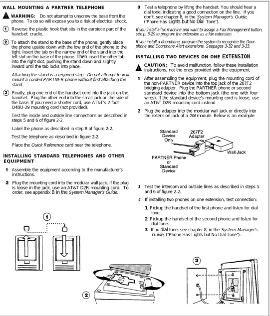
WALL MOUNTING A PARTNER TELEPHONE
WARNING: Do not attempt to unscrew the base from the phone. To do so will expose you to a risk of electrical shock.
Reverse the plastic hook that sits in the earpiece part of the handset cradle.
To attach the stand to the base of the phone, gently place the phone upside down with the low end of the phone to the tight. Insert the tab on the narrow end of the stand into the
left slot on the base of the phone. Then insert the other tab
into the right slot, pushing the stand down and slightly inward until the tab locks into place.
Attaching the stand is a required step. Do not attempt to wall mount a corded PARTNER phone without first attaching the stand.
Finally, plug one end of the handset cord into the jack on the handset. Plug the other end into the small jack on the side of the base. If you need a shorter cord, use AT&T’s 2-foot D4BU-29 mounting cord (not provided).
Test the inside and outside line connections as described in steps 5 and 6 of figure 2-2.
Label the phone as described in step 8 of figure 2-2.
Test the telephone as described in figure 2-2.
Place the Quick Reference card near the telephone.
lNSTALLING STANDARD TELEPHONES AND OTHER EQUIPMENT
Assemble the equipment according to the manufacturer’s instructions.
Plug the mounting cord into the modular wall jack. If the plug is loose in the jack, use an AT&T D2R mounting cord. To
order, see appendix B in the System Manager’s Guide.
Test a telephone by lifting the handset. You should hear a dial tone, indicating a good connection on the line. If you don’t, see chapter 8, in the System Manager’s Guide,
(“Phone Has Lights but No Dial Tone”).
If you install a fax machine and want to assign a Fax Management button, see p. 3-29 to program the extension as a fax extension.
If you install a doorphone, program the system to recognize the Door-phone and DoorDoor-phone Alert extensions. Seepages 3-32 and 3-33.
INSTALLING TWO DEVICES ON ONE
EXTENSION
2
3
4
CAUTION: To avoid malfunction, follow these installation instructions, not the ones provided with the equipment.
After assembling the equipment, plug the mounting cord of the non-PARTNER device into the top jack of the 267F2 bridging adapter. Plug the PARTNER phone or second standard device into the bottom jack (the one with four wires). If the standard device’s mounting cord is loose, use an AT&T D2R mounting cord instead.
Plug the adapter into the modular wall jack or directly into
the extension jack of a 206 module. Below is an example:
Test the intercom and outside lines as described in steps 5 and 6 of figure 2-2.
If installing two phones on one extension, test connection:
1 Pickup the handset of the first phone and listen for dial
tone.
2 Pickup the handset of the second phone and listen for
dial tone.
3 If no dial tone, see chapter 8, in the System Manager’s
Guide, (“Phone Has Lights but No Dial Tone”).
Figure 2-3 Wall Mounting a PARTNER Telephone and Installing Other Equipment
Removing/Replacing Modules
Removing a Module
To remove a processor or 206 module:
1. Disconnect the AC power cord from the wall outlet.
2. Remove the control unit cover by sliding it directly off the backplane.
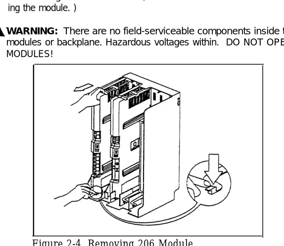
3. Grasp the front top of the module with one hand while holding down the locking tab at the base of the module with the other hand. With the locking tab down, put one finger of the same hand in the wire bracket on the bot-tom front of the module. Using both hands, pull the module forward and out, being careful not to strain the wires connected to the module. (If there is not enough slack in the wires, label and disconnect them before remov-ing the module. )
WARNING: There are no field-serviceable components inside the 206 modules or backplane. Hazardous voltages within. DO NOT OPEN THE MODULES!
Replacing a Module
Figure 2-4. Removing 206 Module
To replace a defective processor or 206 module:
1.
2.
3.
4.
5.
Complete the steps above for removing the module.
Disconnect the first telephone line from the old module and connect it to the new module. Repeat for the second telephone line (if applicable).
Disconnect the first extension line from the old module and connect it to the new module. Repeat for the other extensions.
Insert the new module as described on page 2-2.
Connect the AC power cord. The system performs the necessary reset procedures automatically. You should not need to reprogram the system unless you replaced the processor module, or unless you added or removed telephone lines and/or extensions when replacing the 206 modules.
System Programming
3
Alphabetic List of Procedures
Abbreviated Ringing Allowed List Assignment Allowed Phone Number Lists Automatic Privacy
Calling Group Extensions Copy Settings
Dial Mode
Disallowed List Assignment Disallowed Phone Number Lists Display Language
Doorphone 1 Extension Doorphone 2 Extension Doorphone Alert Extensions Emergency Phone Number List Fax Machine Extensions Hold Disconnect Time Hotline
Line Assignment Line Type
Line Use Restriction Music On Hold Night Service Button Night Service Group Number of Lines
Outgoing Call Restrictions Outside Conference PBX Dial-Out Code Pickup Group Extensions Recall Timer Duration Rotary Dialing Timeout System Date
System Day System Password
SystemReset—ProgrammingSaved System Speed Dial Numbers System Time
Toll Call Prefix Transfer Return Rings
Overview
This chapter provides instructions for programming your system. Your PARTNER Plus system was programmed at the factory so that it works when installed. However, the needs of your business may require that you change some or all of the factory settings. System programming allows you to change these factory settings.
For example, each year when the time changes from Standard Time to Daylight Savings Time, you will want to change the system time. This change is easy to make through system programming. System programming also lets you customize the system to work best for your business. For example, you may not want all extensions to have all outside lines. Using system programming, you can assign lines on an extension-by-extension basis.
Programming Methods
The PARTNER Plus system has more than 30 system programming procedures, each identified by a 3-digit code. Using these codes, you can program the system in one of two ways:
■
■
Direct Method. With this method, you enter the procedure’s 3-digit code followed by data. This method is best for completing one or two procedures at a sitting.
Cycle Method. With this method, you cycle through the procedures in numerical order. This method is best for programming the system the first time or for changing several settings. You can skip procedures without changing their settings.
Detailed instructions for programming are included in the rest of this chapter, beginning on p. 3-4. Once you are familiar with the basic programming steps, the Programming Quick Reference on the inside back cover of this guide especially useful. This chart lists all the procedures and possible settings.
The Programming Extension
System programming must be performed at extension 10 on a PARTNER display phone. As you program, messages on the display prompt you to enter data. You can program the system with the handset on or off the phone; you may even be on a call. This capability is useful for working with technical support personnel on troubleshooting. However, you cannot be on the speaker or microphone during programming.
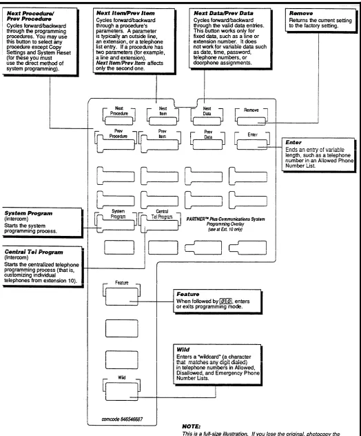
The Programming Overlay
The normal functions of several buttons on the PARTNER display phone at extension 10 change during system programming. For example, the left [ Intercom ] button becomes [ System Program ], the button used to enter program mode. To identify these buttons while programming, place the programming overlay provided with the system on the dial pad of extension 10. Figure 3-1 shows the programming overlay with descriptions of the special buttons.
General Instructions
Remember to place the program-ming overlay on the dial pad of extension 10 before starting.
When you go to another pro-cedure, start with step 2 of the instructions for the new pro-cedure.
You can also exit program mode by lifting and replacing the handset, or by replacing it if it has been lifted.
Programming the PARTNER Plus system requires no complicated steps or intensive training. By following the detailed instructions given in the rest of this chapter, you can quickly change system settings. As you become familiar with programming, use the Programming Quick Reference on the inside back cover of this guide for procedure codes and settings.
The detailed instructions for each procedure include:
■ A brief description of the procedure
■ Valid data entries or procedure settings
■ Considerations for how the procedure interacts with other procedures (if appropriate)
■ Programming notes and steps including:
■ Entering system program mode
■ Selecting the procedure
■ Selecting items—lines, extensions, list, and phone numbers—if necessary
■ Entering data
The instructions use the initial factory setting (designated with an ✔ in the valid entries section). if your system has been previously programmed, the displays may differ.
Once you’ve completed the steps in the detailed instructions, the data setting is saved. You can now
■ go to another procedure,
■ return the data to the factory setting, or
■ exit program mode.
Instructions for these choices are given in the box shown on the bottom of every two pages:
✔ = Factory Setting
To go to the next procedure: [ Next Proc ] To go to a specific procedure: [ # ] [ x ] [ x ] [ x ] [ x ] To go to the previous procedure: [ Prev Proc ] (where XXX is the procedure number) To return data to the factory setting: [ Remove ] To exit system programming: [ Feature ] [ 0 ] [ 0 ]
Programming Procedures
System Date
Code:
#101If your system has been previ- Description: The month, day, and year that appears on PARTNER display ously programmed, the displays
phones may differ.
Valid Entries: Any date
Programming Steps:
1. Press [ Feature ] [ 0 ] [ 0 ] [ System Program ] [ System Program ] [ # ] [ 1 ] [ 0 ] [ 1 ] . display reads:
System Date Data 010100
2. Enter today’s date in the form MMDDYY, using leading zeroes for all single-digit months and dates. For example, to enter December 4, 1990, press [ 1 ] [ 2 ] [ 0 ] [ 4 ] [ 9 ] [ 0 ] . The display reads:
See the box at the bottom of this page for a summary of options of what to do next.
System Day
System Date Data 120490
Code: #102
Description: The day of the week that appears on PARTNER display phones
Valid Entries: ✓ 1 = Sunday 4 = Wednesday 6 = Friday 2 = Monday 5 = Thursday 7 = Saturday 3 = Tuesday
Programmi ng Steps:
1. Press [ Feature ] [ 0 ] [ 0 ] [ System Program ] [ System Program ] [ # ] [ 1 ] [ 0 ] [ 2 ] . display reads:
System Day 1 Sun
2. Change the day by entering a new setting number as listed above. example, to set the day to Tuesday, press [ 3 ]
.
The display reads:System Day 3 Tue
For
Or press [ Next Data ] or [ Prev Data ] until the correct day of the week shows on the display.
✓ = Factory Setting
System Time
Code: #103Description: The time, in 24-hour military-style notation
Valid Entries: Any time
Even though you enter the time in Programming Notes: Enter the time in 24-hour notation, commonly known as 24-hour notation, it appears on
display phones as a.m. and p.m. military time. In this scheme, the hours of the day are 0000 (12 midnight) to after you program it. 2359 (11:59 p.m.). Since each time must have four digits, use leading zeroes
when necessary. For example, to set the time to 9:00 a.m., enter [ 0 ] [ 9 ] [ 0 ] [ 0 ] . To set the time to 4:45 p.m., enter [ # ] [ 1 ] [ 0 ] [ 3 ] .
Programming Steps:
1. Press [ Feature ] [ 0 ] [ 0 ] [ System Program ] [ System Program ] [ # ] [ 1 ] [ 0 ] [ 3 ]. The display reads:
System Time Data 0000
2. Enter a new time in 24-hour notation. For example, to set the time to 2:15 p.m., press [ 1 ] [ 4 ] [ 1 ] [ 5 ]. The display reads:
System Time Data 1415
Number of Lines
Code: #104Description: Use this procedure as a quick way to assign the same number of outside lines to all extensions when first setting up the system. You can assign all or only some of the outside lines to all extensions. If you assign fewer lines than the total number of lines in the system, the system assigns the lines in order. For example, if you assign 5 lines but there are 8 outside lines, the sys-tem assigns lines 1 through 5 to all extensions.
Valid Entries: 0 through 8 lines
✔ 2 lines per 206 module installed
Considerations:
To add or delete specific lines on specific extensions, use procedure #301, Line Assignment.
If you later add more lines to the system, use procedure #301 to assign them to extensions rather than this procedure, which returns the Line Assignment (#301 ), Automatic Line Selection (p. 4-3), and Line Ringing Options (p. 4-4) to the factory settings.
Programming Steps:
1. Press [ Feature ] [ 0 ] [ 0 ] [ System Program ] [ System Program ] [ # ] [ 1 ] [ 0 ] [ 4 ]. The display reads:
Number Of Lines 8 Lines
2. Enter the correct number of lines. For example, to tell the system there are 7 outside lines, press [ 7 ] . The display reads:
Number Of Lines 7 Lines
Transfer Return
Code: #105Rings
Description: Defines the number of times an extension should ring with a transferred call before the call returns to the originating extension.Valid Entries: 0 (transferred calls not returned to originating extension) 1 through 9
✓ 4
Considerations: If you have a fax machine or an answering machine connected to the system, set this number greater than the number of rings these devices wait before answering. This value prevents a call transferred to these machines from returning before it is answered.
Programming Steps:
1. Press [ Feature ] [ 0 ] [ 0 ] [ System Program ] [ System Program ] [ # ] [ 1 ] [ 0 ] [ 5 ] . The display reads:
Transfer Return 4 Rings
2. Enter a different setting. For example, to set a transfer return of 5 rings, press [ 5 ] . The display reads:
Transfer Return 5 Rings
PBX Dial-Out Code
Code:#106
Description: If your system is connected to a PBX (Private Branch Exchange) or a Centrex system instead of directly to the local telephone
See appendix A for more infor- company’s switching system, use this procedure to identify the digit you dial to
mation on programming for PBX
and Centrex. get an outside line.
Valid Entries: 0 through 9 ✓ 9
Consideration:
■ Use procedure #202, Line Type, to identify the lines that are connected to the PBX or Centrex.
■ Do not include the dial-out code in System Speed Dial, Personal Speed Dial, and Auto Dial numbers. The system automatically supplies it.
Programming Steps:
1. Press [ Feature ] [ 0 ] [ 0 ] [ System Program ] [ System Program ] [ # ] [ 1 ] [ 0 ] [ 6 ] . The display reads:
PBX DialOut Code Data 9
2. Enter the correct dial-out code. For example, if you dial [ 8 ] to dial out, press [ 8 ]. The display reads:
Recall Timer
Code: #107Duration
Description: Changes the length of the timed signal (a switchhook flash) exe-cuted by the Recall feature (p. 4-8) and by the Recall function of speed dialing (p. 3-36). Recall sends this timed signal over the phone line to the local tele-phone company or PBX/Centrex to which the system is connected. Typically you use the Recall feature to access PBX or Centrex features such as Call Waiting.Change the factory setting of the recall timer only under three conditions:
■ If your PARTNER Plus system is connected to Centrex, set the recall timer to 800 milliseconds (msec) by entering [ 3 ] [ 2 ].
■ If your PARTNER Plus system is connected to a PBX or Centrex and Recall drops calls, shorten the time.
■ If pressing Recall has no effect, lengthen the time.
Valid Entries: 01 through 80 (25 to 2000 msec in 25 msec increments) ✓ 18 (450 msec)
Programming Steps:
1. Press [ Feature ] [ 0 ] [ 0 ] [ System Program ] [ System Program ] [ # ] [ 1 ] [ 0 ] [ 7 ] . The display reads:
Recall Timer 18 450-msec
2. Enter a different recall timer setting by pressing [ Next Data ] or [ Prev Data ]. For example, to shorten the recaIl timer to 400 msec, press [ Prev Data ] twice. The display reads:
Recall Timer 16 400-msec
Or enter the setting number directly. For example, to set the recall timer to 800 msec, press [ 3 ] [ 2 ].
3. If you are using Recall to access PBX or Centrex features, test the new Recall Timer Duration by trying to use these features:
■ If the call is disconnected, shorten the time.
■ If the Recall signal has no effect, lengthen the time.
✓ = Factory Setting
To go to the next procedure: [ Next Proc ] To go to a specific procedure: [ # ] [ x ] [ x ] [ x ] [ x ] To go to the previous procedure: [ Prev Proc ] (where XX X is the procedure number)
To return data to the factory setting: [ Remove ] To exit system programming: [ Feature ] [ 0 ] [ 0 ]
Rotary
Dialing
Code:#108
Time out
Description: If you have any rotary lines and are having trouble calling out on standard touch-tone phones, use this procedure to change the length of the Rotary Dialing Timeout. For example, if users dial slowly and calls are not com-pleted or are connected to wrong numbers, lengthen the timeout. Do not change this setting unless the system is experiencing problems.Valid Entries: 1 = 4 seconds ✓ 2 = 8 seconds 3 = 12 seconds
Considerations:
Use this procedure only if the Dial Mode (#201) for at least one outside line in the system is set to rotary.Programming Steps:
1. Press [ Feature ] [ 0 ] [ 0 ] [ System Program ] [ System Program ] [ # ] [ 1 ] [ 0 ] [ 8 ] . The display reads:
Rotary Timeout 2 8-secs
2. Change the Rotary Dialing Timeout by entering the setting number as listed above. For example, to lengthen the Rotary Dialing Timeout to 12 seconds, press [3] . The display reads:
Rotary Timeout 3 12-sees
Outside Conference
Code: #109Description: Prevents everyone on the system from including outside parties in conference calls.
Valid Entries: ✓ 1 = Allow conference calls with outside parties 2 = Deny conference calls with outside parties
Programming Steps:
1. Press [ Feature ] [ 0 ] [ 0 ] [ System Program ] [ System Program ] [ # ] [ 1 ] [ 0 ] [ 9 ] . The
display reads:
Outside Conf 1 Allowed
2. To deny conference calls with outside parties, press [ Next Data ] . The display reads:
Dial Mode
Code: #201Description: Identifies each outside line as either touch-tone or rotary.
Valid Entries: ✓ 1 = Touch-tone line 2 = Rotary line
Considerations: If you are using touch-tone phones on rotary lines, you may need to adjust the Rotary Dialing Timeout (#108).
Programming Steps:
1. Press [ Feature ] [ 0 ] [ 0 ] [ System Program ] [ System Program ] [ # ] [ 2 ] [ 0 ] [ 1 ] . The display reads:
Dial Mode Line:
2. Enter the first line to be programmed. For example, to program line 8, press [ 8 ] . The display reads:
Dial Mode L8 1 Touch Tone
3. To change the dial mode, press [ Next Data ] . The display reads:
Dial Mode L8 2 Rotary
To program another line, press [Next Item] or [ Prev Item ] until the correct line number shows on the display. Follow step 3 to change the dialing mode. Repeat for all lines that you want to change.
✓ = Factory Setting
To go to the next procedure: [ Next Proc ] To go to a specific procedure: [ # ] [ 2 ] [ 0 ] [ 1 ] . The To go to the previous procedure: [ Prev Proc ] (where XXX is the procedure number) To return data to the factory setting: [ Remove ] To exit system programming: [ Feature ] [ 0 ] [ 0 ]
Line Type
Code: #202Description: Identifies each outside line as being connected to the local tele-phone company or to a PBX or a Centrex system. See appendix A for more information on programming for PBX or Centrex.
Valid Entries: ✓ 1 = CO (local telephone company line) 2 = PBX or Centrex line
Considerations:
■ If any lines are connected to a PBX or a Centrex system, use procedure
#106, PBX Dial-Out Code, to identify the PBX/Centrex dial-out code.
■ If any lines are connected to a Centrex system, use procedure #107, Recall
Timer Duration, to change the recall timer to 800 milliseconds.
Programming Steps:
1. Press [ Feature ] [ 0 ] [ 0 ] [ System Program ] [ System Program ] [ # ] [ 2 ] [ 0 ] [ 2 ] . The display reads:
Line Type Line:
2. Enter the first line to be programmed. For example, to program line 1, press [ 1 ]. The display reads:
Line Type L1 1 co
3. To change the line type, press [ Next Data ] . The display reads:
Line Type L1 2 PBX
Hold Disconnect
Code: #203Time
Description: When a caller on hold hangs up, the local telephone company may send a special signal to the PARTNER Plus system to free the line. There are two possible signals: a long signal (450 milliseconds) used by most tele-phone companies, or a short signal (50 milliseconds) used by a few teletele-phone companies. The length of the signal is called the hold disconnect time. If you put a line on hold and the call doesn’t “go away” within a minute or two after the caller hangs up, use this procedure to change the hold disconnect time.If the telephone company sends no signal, changing the hold disconnect time has no effect. In this situation, disconnect held calls manually by taking the call off hold and hanging it up.
Valid Entries: ✓ 1 = Long (450 msec) 2 = Short (50 msec)
Programming Steps:
1. Press [ Feature ] [ 0 ] [ 0 ] [ System Program ] [ System Program ] [ # ] [ 2 ] [ 0 ] [ 3 ] . The display reads:
HoldDisconnct Line:
2. Enter the first line to be programmed. For example, to program line 2, press [ 2 ] . The display reads:
HoldDisconnct L2 1 Long
3. To change the disconnect time, press [ Next Data ] . The display reads:
HoldDisconnct L2 2 Short
To program another line, press [ Next Item ] or [ Prev Item ] until the correct line number shows on the display. Follow step 3 to change the disconnect time. Repeat for each line in the system.
✓ = Factory Setting
To go to the next procedure: [ Need Proc ] To go to a specific procedure: [ # ] [ x ] [ x ] [ x ] To go to the previous procedure: [ Prev Proc ] (where XXX is the procedure number) To return data to the factory setting: [ Remove ] To exit system programming: [ Feature ] [ 0 ] [ 0 ]
Line Assignment
Hotline and doorphone exten-sions should not have outside lines assigned to them, to prevent calls from being made or received on them.
Assigning lines to particular line buttons is useful for grouping similar lines (such as inbound and outbound WATS lines) on adjacent line buttons (such as D and H).
Assign only as many lines to an extension as that extension can use. For example, a PARTNER 6-button phone can have only four outside lines.
Code: #301
Description: Use this procedure to change the line assignments on specific extensions. These changes include adding lines, deleting lines, and setting the order of the lines on a PARTNER phone’s line buttons.
Valid Entries: ✓ 1 = Assigned 2 = Not assigned
Considerations: Use this procedure to fine tune the number of lines assigned to all extensions through procedure #104, Number of Lines. For example, if you used procedure #104 to assign 5 lines to all extensions and there are 8 lines in the system, use procedure #301 to assign lines 6, 7, and 8 to specific exten-sions.
Programming Notes: When you use procedure #301 to assign a line to an extension with a PARTNER phone, the line goes to the first unused line button on the phone. The order in which line buttons are assigned appears at the left. For example, if the extension has no lines assigned to it and you assign
line 4 first, that line is put on line button A. If the extension had two other lines assigned to it, line 4 would be put on line button C.
To change the order of existing line assignments, first unassign the lines and then reassign them in the desired order.
Programming Steps:
1. Press [ Feature ] [ 0 ] [ 0 ] [ System Program ] [ System Program ] [ # ] [ 3 ] [ 0 ] [ 1 ]. The display reads:
LineAssign Extension:
2. Enter the extension number to be programmed (10 through 33). For example, to program extension 15, press [ 1 ] [ 5 ] . The display reads:
LineAssign 15 Line:
3. Enter the line to be assigned or unassigned. For example, to select line 1, press [ 1 ] . The display reads:
LineAssign 15 L1 1 Assigned
If you don’t want an extension to have the line, press [ Next Data ]. The display reads:
LineAssign 15 L1 2 Not Assigned
To program another line for this extension, press [ Next Item ] or [ Prev Item ] until the correct line number shows on the display. Repeat step 3.
Label the line assignments on each PARTNER phone.
Line Use
Code:#302
Restriction
Description: Use this procedure to restrict extensions from receiving and/or making outside calls on specific lines. Since you program line use restrictions for each line at each extension, you can restrict some lines on an extension while not restricting others.Restricting the use of a line is the most extreme way to restrict dial-ing on the PARTNER Plus sys-tem. For example, an extension with a the set to "in only” or "no access,” cannot select the line to dial out, even emergency numbers. There are other, less extreme ways to restrict dialing. See appendix B for a summary of dialing restrictions.
Valid Entries: ✓ 1 = 2 =
3 =
4 =
Programming Steps:
1. Press [ Feature ] display reads:
No restriction (all calls permitted on that line)
Out only (can only make outside calls, not receive them, on that line)
In only (can only receive calls, not make them, on that line)
No access (the line appears on the phone but cannot receive or make calls; can receive transferred calls)
[ 0 ] [ 0 ] [ System Program ] [ System Program ] [ # ] [ 3 ] [ 0 ] [ 2 ]. The
Restrict Extension:
2. Enter the extension to be programmed. For example, to program exten-sion 23, press [ 2 ] [ 3 ]. The display reads:
Restrict 23 Line:
3. Enter the line number to be restricted at this extension. For example, to restrict line 2, press [ 2 ]. The display reads:
Restrict 23 L2 1 No Restriction
4. To change the line restriction for this extension, enter the appropriate
set-ting number listed above. For example, to restrict the line to incoming calls, press [ 3 ]. The display reads:
Restrict 23 L3 3 In Only
To restrict another line at this extension, press [ Next Item ] or [ Prev Item ] until the line number
shows on the display. Repeat step 4.
To restrict another extension, press [ Next Proc ] [ Prev Proc ] (or [ # ] [ 3 ] [ 0 ] [ 2 ] , and begin at step 2.
✓ = Factory Settinq
To go to the next procedure: [ Next Proc ] To go to a specific procedure: [ # ] [ x ] [ x ] [ x ] Togo to the previous procedure: [ Prev Proc ] (where XXX is the procedure number) To return data to the factory setting: [ Remove ] To exit system programming: [ Feature ] [ 0 ] [ 0 ]
Display Language
Code: #303Description: Sets the language on the display of a PARTNER display phone. The language is set for each extension, so phones on the same PARTNER sys-tem can display different languages.
Valid Entries: ✓ 1 = English 2 = Spanish 3 = French If you change the language for
extension 10, the display mes- Programming Steps: sages immediately start
appear-ing in the new language. 1.
2.
3.
Press [ Feature ] [ 0 ] [ 0 ] [ System Program ] [ System Program ] [ # ] [ 3 ] [ 0 ] [ 3 ]. The display reads:
Language Extension:
Enter the extension to be programmed. For example, to program exten-sion 11, press [ 1 ] [ 1 ]. The display reads:
Language 11 1 English
To change the display language, enter the appropriate setting number as listed above. For example, to change the display messages to Spanish, press [ 2 ]. The display reads:
Language 11 2 Spanish
Automatic Privacy
Code: #304Description: Automatically prevents users with the same lines from joining telephone conversations on a specific extension.
This feature is typically used for
extensions connected to fax Valid Entries: 1 = Assigned to extension machines and modems, which ✓ 2 = Not assigned
make and receive data calls that
should not be interrupted. Considerations: A user can override Automatic Privacy with the Privacy feature (p. 4-l0).
Programming Steps:
1. Press [ Feature ] [ 0 ] [ 0 ] [ System Program ] [ System Program ] [ # ] [ 3 ] [ 0 ] [ 4 ]. The display reads:
Auto Privacy Extension:
2. Enter the extension to be programmed. For example, to program exten-sion 16, press [ 1 ] [ 6 ] . The display reads:
Auto Privacy 16 2 Not Assigned
3. To assign Automatic Privacy to the extension, press [ Next Data ] until the display reads:
Auto Privacy 16 1 Assigned
To program another extension, press [ Next Item ] or [ Prev Item ] until the extension number shows on the display. Repeat step 3.
✓ = Factory Setting
To go to the next procedure: [ Next Proc ] To go to a specific procedure: [ # ] [ x ] [ x ] [ x ] To go to the previous procedure: [ Prev Preoc ] (where XXX is the procedure number)
To return data to the factory setting: [ Remove ] To exit system programming: [ Feature ] [ 0 ] [ 0 ]
Abbreviated
Code: #305Ringing
Description: Use this procedure to turn Abbreviated Ringing on or off. When a user is on a call and Abbreviated Ringing is on (the factory setting), an incoming call rings only once. The light next to the line button flashes untilReceptionists, and others who the call is answered or the caller hangs up. This feature prevents an incoming handle many calls quickly, often
turn Abbreviated Ringing off, so call from distracting a user busy on another call. To allow calls to ring repeat-they have an audible reminder of edly at a specific extension, turn Abbreviated Ringing off for that extension. incoming calls. Valid Entries: ✓ 1
= Active/On (incoming calls ring once)
2 = Not active/Off (incoming calls ring repeatedly)
Programming Steps:
1.
Press [ Feature ] [ 0 ] [ 0 ] [ System Program ] [ System Program ] [ # ] [ 3 ] [ 0 ] [ 5 ]. The display readsAbbrev. Ring Extension:
2. Enter the extension to be programmed. For example, to program exten-sion 10, press [ 1 ] [ 0 ]. The display reads:
Abbrev. Ring 10 1 Active
3. To turn Abbreviated Ringing off, press [ Next Data ] until the display reads:
Abbrev. Ring 10 2 Not Active
Copy Settings
Code: #399Description: Copies the following settings from any extension to any other extension:
#301 Line Assignment #408 Allowed List Assignment #302 Line Use Restriction #501 Pickup Group Extensions #303 Display Language #502 Calling Group Extensions #304 Automatic Privacy #504 Night Service Group #305 Abbreviated Ringing #601 Fax Machine Extensions #401 Outgoing Call Restrictions Automatic Line Selection (p. 4-3) #405 Disallowed List Assignment Line Ringing Options (p. 4-4)
Valid Entries: Any valid source extension number (the extension copied from) and any valid target extension number (the extension copied to)
Progamming Notes: This procedure is skipped in the sequence of program-ming procedures. To use this procedure, enter the procedure code directly (see step 1).
Programming Steps:
1. Press [Feature ] [ 0 ] [ 0 ] [ System Program ] [ System Program ] [ # ] [ 3 ] [ 9 ] [ 9 ] . The display reads:
Copy Extension:
2. Enter the extension to copy from. For example, to copy extension 18, press [ 1 ] [ 8 ] . The display reads:
Copy 18 Data
--3. Enter the extension to copy to. Any extension except the source extension is valid. For example, to copy to extension 22, press [ 2 ] [ 2 ] . The display reads:
Copy 18 Data 22
To copy the same settings to another extension, enter the new extension number.
To copy another extension’s settings, press [ Next Item ] or [ Prev Item ] until the extension shows on the display. Repeat step 3.
✓ = Factory Setting
To go to the next procedure: [ Next Proc ] To go to a specific procedure: [ # ] [ x ] [ x ] [ x ] To go to the previous procedure: [ Prev Proc ] (where XXX is the procedure number) To return data to the factory setting: [ Remove ] To exit system programming: [ Feature ] [ 0 ] [ 0 ]
Outgoing Call
Code: #401Restrictions
Description: Restricts the types of calls an extension can make. An extension can be restricted to inside calling only, or to local and inside calling. Outgoing While procedures that restrict Call Restrictions apply to all lines assigned to the extension. The System Pass-dialing are very effective,abso-lute protection against misuse word (#403), Emergency Phone Number List (#406), Disallowed and Allowed cannot be guaranteed. Phone Number Lists (#404 and #407) override Outgoing Call Restrictions. PARTNER phones give you more
Valid Entries: ✓ 1 = protection against such misuse
than standard phones. There- 2 =
fore, we strongly recommend that 3 = you install PARTNER phones
where restricting phone use is
important. Programming Steps:
See appendix B for a complete summary of dialing restrictions.
1. Press [ Feature ] [ 0 ] [ 0 ] [ System Program ] [ System Program ] [ # ] [ 4 ] [ 0 ] [ 1 ]. The display reads:
No restriction (can make toll, local, and inside calls) Inside only (can make inside calls only)
Local only (can make local outside and inside calls only)
Call Restrict Extension:
2. Enter the extension to be programmed. For example, to select extension 30, press [ 3 ] [ 0 ] . The display reads:
Call Restrict 30 1 No Restriction
3. To change the type of call restriction, enter the appropriate setting number as listed above. For example, to restrict this extension to local and inter-com calling, press [ 3 ] . The display reads:
Call Restrict 30 3 Local Only
Toll Call Prefix
Code:#402
Description: Phone companies recognize long distance calls in either of two
ways: a telephone number preceded by 0 or 1 plus an area code or a
tele-phone number preceded only by an area code. Use this procedure to tell the PARTNER Plus system which method your phone company uses.
Valid Entries: ✓ 1 = 0 or 1 plus the area code
2 = Area code only (0 or 1 not necessary)
Programming Steps:
1. Press [ Feature ] [ 0 ] [ 0 ] [ System Program ] [ System Program ] [ # ] [ 4 ] [ 0 ] [ 3 ]. The
display reads:
Toll Call Prefix 1 0/1 + AreaCd
2. To change the toll call prefix, press [ Next Data ] until the appropriate setting appears. For example,
Toll Call Prefix 2 Area Code Only
System Password
Code: #403Description: Identifies the 4-digit password that lets a user override Outgoing Call Restrictions (#401). You can also use the password with Night Service (#503 and #504) to restrict after-hours dialing.
Valid Entries: Any 4 digits
Entering the password allows you Considerations: If you assign a password using this procedure, you must enter to override several dialing
restric-tions. See appendix B for a sum- the password when-turning Night Service (#503) on or off. mary of dialing restrictions. Programming Steps:
1. Press [ Feature ] [ 0 ] [ 0 ] [ System Program ] [ System Program ] [ # ] [ 4 ] [ 0 ] [ 3 ]. The display reads:
Set Password
Data----If a password has previously been set, it will appear on the display.
2. Enter or change the password using the dial pad. For example, to set the password to 5747, press [ 5 ] [ 7 ] [ 4 ] [ 7 ] . The display reads:
Set Password Data5747
To remove a password, press [ Remove ]
✓ = Factory Setting
To go to the next procedure: [ Next Proc ] Togo to a specific procedure: [ # ] [ x ] [ x ] [ x ]
To go to the previous procedure: [ Prev Proc ] (where XXX is the procedure number)
To return data to the factory setting: [ Remove ] To exit system programming: [ Feature ] [ 0 ] [ 0 ]
Disallowed
Code: #404Phone Number
Description: Specifies telephone numbers that users cannot dial. For example,Lists
you may want to prevent calls to a specific telephone number or to categories of numbers such as calls to 976 numbers. Use this procedure to create up to four See appendix B for a summary of lists of up to 10 telephone numbers each. Then use procedure #405,dialing restrictions. Disallowed List Assignment, to assign the lists to specific extensions.
Valid Entries: ■ List numbers 1 to 4
■ Maximum 10 telephone numbers per list
■ Maximum 12 digits per telephone number
■ Wildcard character (!) to match any single digit
Programming Steps:
1. Press [ Feature ] [ 0 ] [ 0 ] [ System Program ] [ System Program ] [ # ] [ 4 ] [ 0 ] [ 4 ]. The display reads:
DisallowLst List No:
2. Enter the list to be set up (1 through 4). For example, to select list 1, press [ 1 ]. The display reads:
DisallowLst 1 Entry:
3. Select a list entry (01 through 10). For example, to select entry 01, press [ 0 ] [ 1 ] . The display reads:
DisallowLst 1 01 Data
---4. Enter the first telephone number, following the guidelines given in the “Programming Notes” on the following page. As an example, to prevent local 976 dialing, press [ 9 ] [ 7 ] [ 6 ] . The display reads:
DisallowLst 1 01 Data 976
5. To save the telephone number in memory, press [ Enter ].
To enter other phone numbers in this list, press [ Next Item ] and repeat steps 4 and 5.
To change a phone number, press [ Remove ] and repeat steps 4 and 5.
To delete a phone number, press [ Remove ].
To create another list, press [ # ] [ 4 ] [ 0 ] [ 4 ] and start at step 2 above.
✓ = Factory Setting
The entries for toll calls differ, depending on the Toll Call Prefix (#402). Make sure the Toll Call Prefix is set correctly for your dialing area. If it is not, entries on the Disallowed and Allowed Phone Number Lists may not be handled correctly.
Programming Notes: To program telephone numbers, dial the number as you would normally. You can also use the "wildcard” character to stand for any digit in a phone number. For example, if you want to prevent users from making calls to area codes 202 and 212, you could enter each area code separately or com-bine them in one entry using the wildcard to stand for the middle digit. Using the wildcard, you would press [ 2 ] [ Wild ] [ 2 ] . The wildcard character appears as a “!” on the display: 2 ! 2
When you use the wildcard, be sure that you do not inadvertently prevent a call that should be allowed. In the example above, if we do not include a toll prefix (1 or 0), this entry would prevent calls to exchanges 222, 232, 242, 252, 262, 272, 282, and 292 as well as area codes 202 and 212, since the wildcard matches any digit. The examples below include normally-dialed numbers and wildcards.
■ Specific Telephone Numbers. Dial the telephone number directly, followed by [ Enter ] . For example, to prevent calls to local directory assistance, press
[ 4 ] [ 1 ] [ 1] [ Enter ]..
■ All Telephone Numbers in One Area Code. The following lists use 900 “chat” numbers as