MERLIN LEGEND
TMCommunications System
Release 2.0
Notice
Every effort was made to ensure that the information in this book was complete and accurate at the time of printing. However, information is subject to change.
Federal Communications Commission (FCC) Electromagnetic Interference Information
This equipment has been tested and found to comply with the limits for a Class A digital device, pursuant to Part 15 of the FCC Rules. These limits are designed to provide reasonable protection against harmful interference when the equipment is operated in a commercial environment. This equipment generates, uses, and can radiate radio frequency energy and, if not installed and used in accordance with the instruction manual, may cause harmful interference to radio communications. Operation of this equipment in a residential area is likely to cause harmful interference, in which case the user will be required to correct the interference at his own expense.
Canadian Department of Communications (DOC) Interference Information
This digital apparatus does not exceed the Class A limits for radio noise emissions set out in the radio interference regulations of the Canadian Department of Communications.
Le Présent Appareil Numérique n'émet pas de bruits radioélectriques dépassant Ies Iimites applicable aux appareils numériques de la class A prescribes clans Ie Réglement sur Ie brouillage radioélectrique édicté par Ie ministère des Communications du Canada.
Trademarks
5ESS, ACCUNET, CONVERSANT, Dimension, Horizon, Magic On Hold, MEGACOM, MERLIN, SYSTIMAX, and MultiQuest are registered trademarks and 4ESS, AUDIX Voice Power, FAX Attendant System, InnManager, MERLIN LEGEND, MERLIN MAIL, MLX-10, MLX-10D, MLX-20L, MLX-28D, and MERLIN PFC are trademarks of AT&T in the U.S. and other countries.
Intel is a registered trademark of Intel Corporation.
MS-DOS is a registered trademark of Microsoft Corporation. UNIX is a registered trademark of UNIX System Laboratories, Inc.
PagePac is a registered trademark and ZoneMate is a trademark of DRACON, a division of Harris Corporation.
Mirage, StarSet, Supra, and Supra NC are registered trademarks of Plantronics, Inc.
Support Telephone Number
About This Book
1■ Terms and Conventions Used 2
■ Product Safety Labels 3
■ Security 3
■ Related Documents 3
■ How to Comment on This Document 5
1
Introduction
1-1■ Components 1-2
■ Functional Description 1-9
■ Modes of Operation 1-12
■ Programming 1-30
■ System Capacities and Requirements 1-33
■ Release Differences 1-43
2
Hardware Components
2-1■ Control Unit 2-1
■ Telephones and Consoles 2-13
■ Adapters and Adjuncts 2-28
■ Power-Related Hardware 2-51
3
Lines and Trunks
3-1■ Loop-Start Lines/Trunks 3-1
■ Ground-Start Lines/Trunks 3-2
■ Tie Trunks 3-2
■ Direct Inward Dialing (DID) Lines/Trunks 3-11
4
Applications
4-1■ Voice Messaging Systems
■ MERLIN MAIL Voice Messaging System
■ MERLIN Attendant
■ Call Accounting System (CAS)
■ Call Accounting Terminal (CAT)
■ Call Management System (CMS)
■ InnManager Guest Management System
■ System Programming and Maintenance (SPM)
■ Integrated Solution II (IS II) ■ Integrated Solution Ill (IS Ill)
■ Primary Rate Interface (PRI) Applications
■ Centrex Operation
■ MERLIN PFC Telephone
■ Automated Document Delivery System (ADDS)
■ CONVERSANT Intro
■ Applications Printers
4-4 4-9 4-16 4-20 4-23 4-26 4-30 4-31 4-33 4-40 4-50 4-52 4-56 4-58 4-60 4-62
5
Data Communications Support
5-1■ Data Communications Configuration Overview 5-2
■ Outside Trunks 5-13
■ System Features Used For Data 5-16
■ Endpoint Communications Features 5-18
A
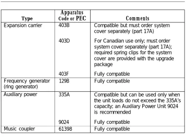
Product Ordering Information
A-1GL
Glossary
GL-11
Introduction
Figure 1-1. Figure 1-2. Figure 1-3. Figure 1-4. Figure 1-5. Figure 1-6. Figure 1-7. Figure 1-8.System Components 1-6
Functional Units 1-10
Lines Labeled for Key System Telephones 1-15 Lines Labeled for Modified Key System
Telephones 1-17
Hybrid/PBX Mode 1-19
Behind Switch Mode 1-23
Behind Switch Mode with Direct Outside
Trunks 1-24
Labeled Line Buttons for Behind Switch
Telephones 1-25
2
Hardware Components
Figure 2-1, Carriers
Figure 2-2. Processor Module Figure 2-3. Power Supply
Figure 2-4. Line/Trunk and Station Modules Figure 2-5. Control Unit Cover
Figure 2-6. MLX-28D Telephone Figure 2-7. MLX-20L Telephone Figure 2-8. MLX-10D Telephone Figure 2-9. MLX-10 Telephone Figure 2-10. Direct Station Selector
Figure 2-11. 551 T1 L1 Channel Service Unit Connections Figure 2-12, ESF T1 Channel Service Unit Connections Figure 2-13. Multi-Function Module
Figure 2-14. GPA Connections
Figure 2-15. 7500B Data Module Front Panel Figure 2-16. 7500B Data Module Back Panel Figure 2-17. SAA Connections
Figure 2-18. Headsets
Figure 2-19. Analog Multi line Telephone Headset Figure 2-20. Analog IROB Connection
Figure 2-21, MLX IROB Connection
Figure 2-22. Figure 2-23. Figure 2-24. Figure 2-25.
Surge Protectors 2-57
Trouble Alarm Connections 2-59
Power Failure Alarm Connections 2-59 Power Failure DID Busy-Out Connections 2-60
3
Lines and Trunks
Figure 3-1. Setting the 400EM Module DIP Switches for
E&M Signaling Types 1C and 5 3-6 Figure 3-2. Nontandem Tie-Trunk Network 3-11
5
Data Communications Support
Figure 5-1. Individual Use Data Station Configurations 5-3 Figure 5-2. Direct RS-232 Interface 5-20 Figure 5-3. RS-232 to V.35 Interface Conversion 5-22
Figure 5-4. Direct V.35 Interface 5-24
1
Introduction
Table 1-1, Modes of Operation Summary 1-12 Table 1-2. FCC Registration Numbers 1-28 Table 1-3. Hardware and Software Capacities 1-34 Table 1-4. Environmental Specifications 1-37
2
Hardware Components
Table 2-1. Table 2-2. Table 2-3. Table 2-4, Table 2-5. Table 2-6. Table 2-7. Table 2-8. Table 2-9.
Line/Trunk and Station Modules Reusable MERLIN II Modules Reusable MERLIN II Hardware Analog Multiline Telephones Single-Line Telephones
Telephones and Adjuncts Not Supported Maximum Number of System Operator Positions
Adjunct Summary
Local Auxiliary Power Requirements
2-7 2-11 2-12 2-21 2-22 2-23 2-24 2-28 2-52
3
Lines and Trunks
Table 3-1. Setting the 400EM Module DIP Switches 3-7 Table 3-2. Sample DIP Switches for the 400EM Module 3-7
Table 3-3. Tie-Trunk Compatibility 3-9
Table 3-4. Type 1 Standard and Type 1 Compatible
E&M Switch Settings 3-1o
Table 3-5. Line Compensation Settings 3-20
4
Applications
Table 4-1. Application Capacities and Modes of
Operation 4-3
Table 4-2. Mode Codes 4-6
Table 4-3. TTRs Required by Voice Messaging Systems 4-7 Table 4-4. MERLIN MAIL Voice Messaging System
Table 4-5. MERLIN Attendants Required 4-19
Table 4-6. Voice Channels Required 4-35
Table 4-7. Voice Channels Required 4-49
Table 4-8. Applications Printers 4-62
5
Data Communications Support
instructions in the literature accompanying the product.
IMPORTANT SAFETY INSTRUCTIONS
When installing telephone equipment, always follow basic safety precautions to reduce the risk of fire, electrical shock, and injury to persons, including:
■ Read and understand all instructions.
■ Follow all warnings and instructions marked on or packed with the
product.
■ Never install telephone wiring during a lightning storm,
■ Never install a telephone jack in a wet location unless the jack is
specifically designed for wet locations.
■ Never touch uninsulated telephone wires or terminals unless the telephone wiring has been disconnected at the network interface.
■ Use caution when installing or modifying telephone lines.
■ Use only AT&T-manufactured MERLIN LEGEND™ Communications
System circuit modules, carrier assemblies, and power units in the MERLIN LEGEND Communications System (511A) control unit.
■ Use only AT&T-recommended/approved MERLIN LEGEND
Communications System accessories.
■ If equipment connected to the analog station modules (008, 408,
408 GS/LS) or to the MLX telephone modules (008 MLX, 408 GS/LS-MLX) is to be used for in-range out-of-building (IROB) applications, IROB protectors are required.
■ Do not install this product near water, for example, in a wet basement location.
■ Do not overload wall outlets, as this can result in the risk of fire or
electrical shock.
■ The MERLIN LEGEND Communications System is equipped with a three-wire grounding-type plug with a third (grounding) pin. This plug will fit only into a grounding-type power outlet. This is a safety feature, If you are unable to insert the plug into the outlet, contact an electrician to replace the obsolete outlet. Do not defeat the safety purpose of the grounding plug.
■ Slots and openings in the module housings are provided for ventilation. To protect this equipment from overheating, do not block these
openings.
■ Never push objects of any kind into this product through module openings or expansion slots, as they may touch dangerous voltage points or short out parts, which could result in a risk of fire or electrical shock. Never spill liquid of any kind on this product.
■ Unplug the product from the wall outlet before cleaning. Use a damp cloth for cleaning. Do not use cleaners or aerosol cleaners. Auxiliary equipment includes answering machines, alerts, modems, and fax machines. To connect one of these devices, you must first have a
Multi-Function Module (MFM).
WARNING:
■ For your personal safety, DO NOT install an MFM yourself. ■ ONLY an authorized technician or dealer representative shall
install, set options, or repair an MFM.
■ To eliminate the risk of personal injury due to electrical shock,
DO NOT attempt to install or remove an MFM from your MLX telephone. Opening or removing the module cover of your telephone may expose you to dangerous voltages.
Support Telephone Number
In the U.S.A. only, AT&T provides a toll-free customer Helpline
(1-800-628-2888) 24 hours a day. Call the Helpline, or your authorized dealer, if you need assistance when installing, programming, or using your system.
Outside the U. S. A., if you need assistance when installing, programming, or
using your system, contact your authorized AT&T dealer.
Federal Communications Commission (FCC) Electromagnetic Interference Information
This equipment has been tested and found to comply with the limits for a Class A digital device, pursuant to Part 15 of the FCC Rules. These limits are designed to provide reasonable protection against harmful interference when the equipment is operated in a commercial environment. This equipment generates, uses, and can radiate radio frequency energy and, if not installed and used in accordance with the instruction manual, may cause harmful interference to radio communications, Operation of this equipment in a residential area is likely to cause harmful interference, in which case the user will be required to correct the interference at his own expense.
Canadian Department of Communications (DOC) Interference Information This digital apparatus does not exceed the Class A limits for radio noise emissions set out in the radio interference regulations of the Canadian Department of Communications,
Le Présent Appareil Numérique n'émet pas de bruits radioelectriques depassant Ies Iimites applicable aux appareils numériques de la class A prescribes clans Ie reglement sur Ie brouillage radioelectrique edicté par Ie ministère des Communications du Canada.
FCC Notification and Repair Information
■ Means of Connection. Connection of this equipment to the telephone
network shall be through a standard network interface jack:
USOC RJ11C, RJ14C, RJ21X. Connection to E&M tie trunks requires a USOC RJ2GX. Connection to off-premises stations requires a
USOC RJ11C or RJ14C. Connection to 1.544-Mbps digital facilities must be through a USOC RJ48C or RJ48X. Connection to DID requires a USOC RJ11C, RJ14C, or RJ21X. These USOCs must be ordered from your telephone company.
This equipment may not be used with party lines or coin telephone lines.
■ Notification to the Telephone Companies. Before connecting this
equipment, you or your equipment supplier must notify your local telephone company’s business office of the following:
— The telephone number(s) you will be using with this equipment. — The appropriate registration number and ringer equivalence
number (REN), which can be found on the back or bottom of the control unit, as follows:
If this equipment is to be used as Key System, report the number AS593M-72914-KF-E.
If the system provides both manual and automatic selection of incoming/outgoing access to the network, report the number AS593M-72682-MF-E.
If there are no directly terminated trunks, or if the only directly terminated facilities are personal lines, report the number AS5USA-65646-PF-E.
The REN for all three systems is 1.5A.
— For tie line connection, the facility interface code (FIC) is TL31 M and the service order code (SOC) is 9.0F.
— For connection to off-premises stations, the FIC is OLI3C and the SOC is 9.0F.
— For equipment to be connected to 1.544-Mbps digital service, the FIC is 04DU9-B for D4 framing format or 04DU9-C for extended framing format, and the SOC is 6.0P.
— For equipment to be connected to DID facilities, the FIC is 02RV2-T and the SOC is 9.0F.
— The quantities and USOC numbers of the jacks required. — For each jack, the sequence in which lines are to be connected:
the line types, the FIC, and the REN by position when applicable. You must also notify your local telephone company if and when this equipment is permanently disconnected from the line(s).
Installation and Operational Procedures
The manuals for your system contain information about installation and operational procedures.
■ Repair Instructions. If you experience trouble because your equipment
is malfunctioning, the FCC requires that the equipment not be used and that it be disconnected from the network until the problem has been corrected. Repairs to this equipment can be made only by the
manufacturers, their authorized agents, or others who may be authorized by the FCC. In the event repairs are needed on this equipment, contact your authorized T&T dealer or, in the U.S.A. only, contact the National Service Assistance Center (NSAC) at 1-800-628-2888.
■ Rights of the Local Telephone Company. If this equipment causes
harm to the telephone network, the local telephone company may discontinue your service temporarily. If possible, they will notify you in advance. But if advance notice is not practical, you will be notified as soon as possible. You will also be informed of your right to file a complaint with the FCC.
Your local telephone company may make changes in its facilities, equipment, operations, or procedures that affect the proper functioning of this equipment. If they do, you will be notified in advance to give you an opportunity to maintain uninterrupted telephone service.
■ Hearing Aid Compatibility. The custom telephone sets for this system
are compatible with inductively coupled hearing aids as prescribed by the FCC.
■ Automatic Dialers. WHEN PROGRAMMING EMERGENCY NUMBERS
AND/OR MAKING TEST CALLS TO EMERGENCY NUMBERS:
— Remain on the line and briefly explain to the dispatcher the reason for the call.
— Perform such activities in off-peak hours, such as early morning or late evening.
■ Direct Inward Dialing (DID).
a. This equipment returns answer supervision signals to the Public Switched Telephone Network when:
(1) answered by the called station (2) answered by the attendant
(3) routed to a recorded announcement that can be
administered by the customer premises equipment user (4) routed to a dial prompt
b. This equipment returns answer supervision on all DID calls forwarded back to the Public Switched Telephone Network, Permissible exceptions are when:
Allowing this equipment to be operated in such a manner as not to provide proper answer supervision signaling is in violation of Part 68 rules.
DOC Notification and Repair Information
NOTICE: The Canadian Department of Communications (DOC) label identifies
certified equipment. This certification means that the equipment meets certain telecommunications network protective, operational, and safety requirements. The DOC does not guarantee the equipment will operate to the user’s
satisfaction.
Before installing this equipment, users should ensure that it is permissible to connect it to the facilities of the local telecommunications company. The equipment must also be installed using an acceptable method of connection. In some cases, the company’s inside wiring for single-line individual service may be extended by means of a certified connector assembly (telephone extension cord). The customer should be aware that compliance with the above conditions may not prevent degradation of service in some situations.
Repairs to certified equipment should be made by an authorized Canadian maintenance facility designated by the supplier. Any repairs or alterations made by the user to this equipment, or any equipment malfunctions, may give the telecommunications company cause to request the user to disconnect the equipment.
Users should ensure for their own protection that the electrical ground
connections of the power utility, telephone lines, and internal metallic water pipe system, if present, are connected. This precaution may be particularly
important in rural areas.
CAUTION: Users should not attempt to make such connections themselves, but
should contact the appropriate electrical inspection authority or electrician, as appropriate.
To prevent overloading, the Load Number (LN) assigned to each terminal device denotes the percentage of the total load to be connected to a telephone loop used by the device. The termination on a loop may consist of any
combination of devices subject only to the requirement that the total of the Load Numbers of all the devices does not exceed 100.
DOC Certification No. 230 4095A CSA Certification No. LR 56260 Load No. 6
Renseignements sur la notification du ministère des Communications du Canada et la réparation
matériel doit également être installé en suivant une méthode acceptée de raccordement. Dans certains cas, Ies fils intérieurs de I’enterprise utilisés pour un service individual à Iigne unique peuvent être prolongés au moyen d’un dispositif homologué de raccordement (cordon prolongateur téléphonique interne). L’abonné ne doit pas oublier qu’il est possible que la conformité aux conditions énoncées ci-dessus n’empêchent pas la degradation du service clans certaines situations. Actuellement, Ies entreprises de télécommunication ne permettent pas que I’on raccorde Ieur matériel à des jacks d’abonné, sauf clans Ies cas précis prévus pas Ies tarifs particuliers de ces entreprises. Les réparations de matériel homologué doivent être effectuées par un centre d’entretien canadien autorisé désigné par Ie fournisseur. La compagnie de télécommunications peut demander à I’utilisateur de débrancher un appareil à la suite de reparations ou de modifications effectuées par I’utilisateur ou à cause de mauvais fonctionnement.
Pour sa propre protection, I’utilisateur doit s’assurer que tous Ies fils de mise à la terre de la source d’énergie électrique, des Iignes téléphoniques et des canalisations d’eau métalliques, s’il y en a, sent raccordés ensemble. Cette precaution est particulièrement importance clans Ies régions rurales.
AVERTISSEMENT: L’utilisateur ne doit pas tenter de faire ces raccordements
lui-même; il doit avoir recours à un service d’inspection des installations électriques, ou à un electrician, selon Ie cas.
L’indite de charge (IC) assigné à chaque dispositif terminal indique, pour éviter toute surcharge, Ie pourcentage de la charge totale qui peut être raccordée à un circuit téléphonique bouclé utilisé par ce dispositif. La terminaison du circuit bouclé peut être constitute de n’importe quelle combinaison de dispositifs, pourvu que la somme des indices de charge de I’ensemble des dispositifs ne dépasse pas 100.
MERLIN LEGEND D.O.C. Ministère des Communications
Location Label Placement du Canada emplacement de
Security of Your System—Preventing Toll Fraud
As a customer of a new telephone system, you should be aware that there exists an increasing problem of telephone toll fraud. Telephone toll fraud can occur in many forms, despite the numerous efforts of telephone companies and telephone equipment manufacturers to control it. Some individuals use
electronic devices to prevent or faIsify records of these calls. Others charge calls to someone else’s number by illegally using lost or stolen calling cards, billing innocent parties, clipping on to someone else’s line, and breaking into someone else’s telephone equipment physically or electronically. In certain instances, unauthorized individuals make connections to the telephone network through the use of remote access features.
The Remote Access feature of your system, if you choose to use it, permits off-premises callers to access the system from a remote telephone by using an 800 number or a 7- or 10-digit telephone number. The system returns an
acknowledgement signaling the user to key in his or her authorization code, which is selected and administered by the system manager. After the
authorization code is accepted, the system returns dial tone to the user. If you do not program specific egress restrictions, the user will be able to place any call normally dialed from a telephone associated with the system. Such an off-premises network call is originated at, and will be billed from the system location.
The Remote Access feature, as designed, helps the customer, through proper administration, to minimize the ability of unauthorized persons to gain access to the network. Most commonly, phone numbers and codes are compromised when overheard in a public location, through theft of a wallet or purse containing access information, or through carelessness (writing codes on a piece of paper and improperly discarding it). Additionally, hackers may use a computer to dial an access code and then publish the information to other hackers. Enormous charges can be run up quickly. It is the customer’s responsibility to take the appropriate steps to properly implement the features, evaluate and administer the various restriction levels, protect access codes, and distribute access codes only to individuals who have been fully advised of the sensitive nature of the access information.
Common carriers are required by law to collect their tariffed charges. While these charges are fraudulent charges made by persons with criminal intent, applicable tariffs state that the customer of record is responsible for payment of all long-distance or other network charges. AT&T cannot be responsible for such charges and will not make any allowance or give any credit for charges that result from unauthorized access.
To minimize the risk of unauthorized access to your communications system:
■ Use a nonpublished Remote Access number.
■ Use random sequence authorization codes, which are less likely to be easily broken.
■ Deactivate all unassigned codes promptly.
■ Ensure that Remote Access users are aware of their responsibility to keep the telephone number and any authorization codes secure.
■ When possible, restrict the off-network capability of off-premises callers, via use of Call Restrictions and Disallowed List capabilities.
■ When possible, block out-of-hours calling.
■ Frequently monitor system call detail reports for quicker detection of any unauthorized or abnormal calling patterns.
■ Limit Remote Call Forward to persons on a need-to-have basis. Limited Warranty and Limitation of Liability
AT&T warrants to you, the customer, that your MERLIN LEGEND
Communications System will be in good working order on the date AT&T or its authorized reseller delivers or installs the system, whichever is later (“Warranty Date”). If you notify AT&T or its authorized reseller within one year of the Warranty Date that your system is not in good working order, AT&T will without charge to you repair or replace, at its option, the system components that are not in good working order. Repair or replacement parts may be new or refurbished and will be provided on an exchange basis. If AT&T determines that your system cannot be repaired or replaced, AT&T will remove the system and, at your option, refund the purchase price of your system, or apply the purchase price towards the purchase of another AT&T system.
If you purchased your system directly from AT&T, AT&T will perform warranty repair in accordance with the terms and conditions of the specific type of AT&T maintenance coverage you selected. If you purchased your system from an AT&T-authorized reseller, contact your reseller for the details of the
maintenance plan applicable to your system.
This AT&T limited warranty covers damage to the system caused by power surges, including power surges due to lightning.
The following will not be deemed to impair the good working order of the system, and AT&T will not be responsible under the limited warranty for damages resulting from
■ failure to follow AT&T’s installation, operation, or maintenance instructions
■ unauthorized system modification, movement, or alteration
■ unauthorized use of common carrier communication services accessed
through the system
■ abuse, misuse, or negligent acts or omissions of the customer and persons under the customer’s control
■ acts of third parties and acts of God
AT&T’S OBLIGATION TO REPAIR, REPLACE, OR REFUND AS SET FORTH ABOVE IS YOUR EXCLUSIVE REMEDY.
EXCEPT AS SPECIFICALLY SET FORTH ABOVE, AT&T, ITS AFFILIATES, SUPPLIERS, AND AUTHORIZED RESELLERS MAKE NO WARRANTIES,
Limitation of Liability
EXCEPT FOR PERSONAL INJURY, DIRECT DAMAGES TO TANGIBLE PERSONAL PROPERTY PROXIMATELY CAUSED BY AT&T, AND LIABILITY OTHERWISE EXPRESSLY ASSUMED IN A WRITTEN AGREEMENT SIGNED BY AT&T, THE LIABILITY OF AT&T, ITS AFFILIATES, SUPPLIERS, AND
AUTHORIZED RESELLERS FOR ANY CLAIMS, LOSSES, DAMAGES, OR EXPENSES FROM ANY CAUSE WHATSOEVER (INCLUDING ACTS OR OMISSIONS OF THIRD PARTIES), REGARDLESS OF THE FORM OF ACTION, WHETHER IN CONTRACT, TORT OR OTHERWISE, SHALL NOT EXCEED AN AMOUNT EQUAL TO THE LESSER OF THE DIRECT DAMAGES PROVEN OR THE PURCHASE PRICE OF THE SYSTEM. IN NO EVENT SHALL AT&T OR ITS AFFILIATES, SUPPLIERS, OR AUTHORIZED RESELLERS BE LIABLE FOR INCIDENTAL, RELIANCE, CONSEQUENTLY, OR ANY OTHER INDIRECT LOSS OR DAMAGE (INCLUDING LOST PROFITS OR REVENUES) INCURRED IN CONNECTION WITH THE SYSTEM. THIS LIMITATION OF LIABILITY SHALL SURVIVE FAILURE OF THE EXCLUSIVE REMEDY SET FORTH IN THE LIMITED WARRANTY ABOVE.
Voice Mail Systems
Your Voice Mail system permits callers to leave verbal messages for system users or gain access to the back-up position in an emergency as well as create and distribute voice messages among system users.
The Voice Mail system, through proper administration, can help you reduce the risk of unauthorized persons gaining access to the network. However, phone numbers and authorization codes can be compromised when overheard in a public location, are lost through theft of a wallet or purse containing access information, or through carelessness (writing codes on a piece of paper and improperly discarding them). Additionally, hackers may use a computer to dial an access code and then publish the information to other hackers. Substantial charges can accumulate quickly. It is your responsibility to take appropriate steps to implement the features properly, evaluate and administer the various restriction levels, protect and carefully distribute access codes.
Under applicable tariffs, you will be responsible for payment of toll charges. AT&T cannot be responsible for such charges and will not make any allowance or give any credit resulting from unauthorized access.
To reduce the risk of unauthorized access through your Voice Mail system, please observe the following procedures:
■ Employees who have voice mailboxes should be required to use the passwords to protect their mailboxes.
— Have them use random sequence passwords.
— Impress upon them the importance of keeping their passwords a secret.
— Encourage them to change their passwords regularly.
■ AUDIX Voice Power™ has the ability to limit transfers to subscribers only. You are strongly urged to limit transfers in this manner.
■ Use the PBX or Key system administration capability to do the following: — Block direct access to outgoing lines and force the use of
account codes/authorization codes.
— Disallow trunk-to-trunk transfer unless required.
— Assign toll restriction levels to all AUDIX Voice Power ports. — If you do not need to use the Outcalling feature, completely
restrict the outward calling capability of the AUDIX Voice Power ports.
■ Monitor SMDR reports or Call Accounting System reports for outgoing calls that might be originated by AUDIX Voice Power ports.
Remote Administration and Maintenance
The Remote Administration and Maintenance feature of your
telecommunications system, if you choose to use it, permits users to change the system features and capabilities from a remote location.
The Remote Administration and Maintenance feature, through proper
administration, can help you reduce the risk of unauthorized persons gaining access to the network. However, telephone numbers and authorization codes can be compromised when overheard in a public location, are lost through theft of a wallet or purse containing access information, or through carelessness (writing codes on a piece of paper and improperly discarding them). Additionally, hackers may use a computer to dial an access code and then publish the information to other hackers. Substantial charges can accumulate quickly. It is your responsibility to take appropriate steps to implement the features properly, evaluate and administer the various restriction levels, and protect and carefully distribute access codes.
Under applicable tariffs, you will be responsible for payment of toll charges. AT&T cannot be responsible for such charges and will not make any allowance or give any credit resulting from unauthorized access.
To reduce the risk of unauthorized access through Remote Administration and Maintenance, please observe the following procedures:
■ The System Administration and Maintenance capability of a PBX or Key system is protected by a password.
— Change the default password immediately. — Continue to change the password regularly.
— Only give the password to people who need it and impress upon them the need to keep it secret.
■ If you have a special telephone line connected to your PBX or Key system for Remote Administration and Maintenance, you should do one of the following:
— Unplug the line when it is not being used.
— Install a switch in the line to turn it off when it is not being used. — Keep the Remote Administration and Maintenance telephone
number secret. Only give it to people who need to know it, and impress upon them the need to keep it a secret. Do not write the telephone number on the PBX or Key system, the connecting equipment, or anywhere else in the system room.
This document covers all aspects of the MERLIN LEGEND™ Communications System Release 2.0, a state-of-the-art telephone switching system that provides both voice and data communication features.
The document is intended for use by anyone who needs detailed information about the hardware and software that apply to the communications system, including support personnel, technicians, sales representatives, and account executives. It describes system components and capabilities, modes of operation, lines and trunks, applications, and data communications support. The following documents may be referenced for additional information:
■ Feature Reference
■ System Planning
■ System Programming
See “Related Documents” later in this section.
In the U.S.A. only, AT&T provides a toll-free customer Helpline
Terms and Conventions Used
In this document, the following terms are used to describe components of the communications system:
■ telephone (synonymous with voice terminal)
■ extension (synonymous with station)
■ control unit (synonymous with switch)
Although the terms line and trunk technically refer to different facilities, they are often used interchangeably. In this document, trunk refers to either facility. Typographical conventions are used in this document to distinguish certain kinds of information. The conventions are as follows:
■ Bold type is used for emphasis and for telephone buttons.
Press Drop to delete the current entry.
■ Constant width type is used for information on telephone display screens or on a PC screen,
Select Sys Program,
■ Bold constant width type indicates information that you enter exactly as shown.
Product Safety Labels
An exclamation point inside a triangle and the word “caution” or “warning” indicate hazardous situations. These product safety labels appear as follows.
WARNING:
Warning indicates the presence of a hazard that could cause death or severe personal injury if the hazard is not avoided.
CAUTION:
Caution indicates the presence of a hazard that could cause minor personal injury or property damage if the hazard is not avoided.
Security
The use of passwords prevents unauthorized users from abusing the communications system. It is strongly recommended that passwords be assigned wherever possible and that the passwords are provided only to those persons directly responsible for system administration and maintenance. Non-displaying access codes and telephone numbers provide another layer of security. The following cautionary note pertains to security:
CAUTION:
For more information about the security of your communications system to prevent toll fraud, see the “Customer Support Information” section at the front of this document.
Related Documents
A number of related documents are available, providing additional information about the communications system. Whenever a reference to a related
document is given within a document, the reference uses a shortened version of the document’s title. For example, MERLIN LEGEND Communications System
Release 2.0 System Programming is referred to as System Programming.
Document No. 555-620-114 555-620-110 555-620-115 555-620-116 555-620-111 555-620-112 555-62~113 555-620-122 555-620-123 555-620-150 555-620-152 555-620-124 555-620-125 555-620-151 555-620-120 555-620-121 555-620-128 555-620-126 555-620-127 555-620-134 555-620-135 555-620-132 555-620-133 555-620-136 555-620-137 555-620-130 555-620-131 555-620-129 555-620-140 555-620-141 555-620-142 555-620-143 555-620-144 Title System Documents System Overview Feature Reference
Equipment and Operations Reference Pocket Reference
System Programming System Planning System Planning Forms
Telephone User Support
MLX-10D, MLX-28D, and MLX-20L Display Telephones User’s Guide
MLX-10D, MLX-28D, and MLX-20L Display Telephones Quick Reference
MLX-10D (Display) Telephone Tray Cards (6 cards) MLX-28D and MLX-20L Telephone Tray Cards (5 cards)
MLX-10 Non-Display Telephone User's Guide MLX-10 Non-Display Telephone Quick Reference
MLX-10 (Non-Display) Telephone Tray Cards (6 cards)
Analog Multiline Telephones User’s Guide Analog Multiline Telephones Quick Reference ML C-5 Cordless Telephone Quick Reference Single-Line Telephones User’s Guide
Single-Line Telephones Quick Reference
System Operator Support
MLX Direct-Line Consoles Operator’s Guide MLX Direct-Line Consoles Quick Reference Analog Direct-Line Consoles Operator’s Guide
Analog Direct-Line Consoles Quick Reference MLX Queued Call Console Operator's Guide
MLX Queued Call Console Quick Reference
Miscellaneous User Support
Calling Group Supervisor’s Guide
Calling Group Supervisor’s Quick Reference Data User’s Guide
Documentation for Qualified Technicians
Installation, Programming, & Maintenance (lP&M) Binder
(consists of 555-620-141,555-620-142, 555-620-143, and 555-620-1 44)
Installation
System Programming & Maintenance (SPM) Maintenance and Troubleshooting
How to Comment on This Document
We welcome your comments about the usefulness of this document. Please tell us what you like, as well as what you would improve. You may use the
feedback form on the next page to let us know how we can continue to serve you. If the feedback form is missing, write directly to:
A. Sherwood AT&T
99 Jefferson Road Room 2A25
The MERLIN LEGEND Communications System is an advanced digital switching system that integrates voice and data communications features. Voice features combine traditional telephone features, such as Transfer and Hold, with
advanced features, such as Group Coverage and Park. Data features enable the transmission of voice and data over the same system wiring. This chapter describes the following aspects of the system:
■ Components—the required and optional equipment that makes up the system
■ Functional Description-the functional units that make up the control unit, their relationships, and the process of signaling
■ Modes of Operation—the three modes for which the system can be configured: Key mode, Hybrid/PBX mode, and Behind Switch mode
■ Programming-general information about programming the system and telephones
■ System Capacities and Requirements—the technical requirements and capacities of the system, for example, hardware and software capacities and environmental, power, and grounding requirements
Components
The system consists of the following basic components and optional auxiliary components:
■ Basic components — Control unit — Telephones
■ Auxiliary components — Adjuncts — Adapters — Applications
Control Unit
The control unit consists of the basic carrier and up to two expansion carriers. The basic carrier contains the processor module, power supply module, and line/trunk and station modules. Each expansion carrier contains a power supply module and line/trunk and station modules.
Telephones
The telephones that can be used with the system are MLX (digital) telephones, analog multiline telephones (including cordless telephones), and single-line telephones.
MLX Telephones
The following MLX telephones can be used:
■ MLX-10D™ (10 buttons with display)
■ MLX-20L™ (20 buttons with display)
■ MLX-28D™ (28 buttons with display)
■ MLX-10™ (10 buttons, no display)
Analog Multiline Telephones
The following analog multiline telephones can be used:
■ 10-button* (10 buttons, membrane)
■ 34-button* (34 buttons, membrane)
■ 34-button Deluxe* (34 buttons, membrane)
■ 10-button HFAI* (10 buttons, hands-free-answer, no adjuncts supported)
■ 34-button BIS* (34 buttons, built-in speakerphone)
■ 34-button BIS/DIS* (34 buttons, built-in speakerphone, 16-character display)
■ BIS-10 (10 buttons, built-in speakerphone)
■ BIS-22 (22 buttons, built-in speakerphone)
■ BIS-22D (22 buttons, built-in speakerphone, 16-character display)
■ BIS-34 (34 buttons, built-in speakerphone)
■ BIS-34D (34 buttons, built-in speakerphone, 16-character display)
■ MLC-5 Cordless (5 buttons, cordless)
■MERLIN PFC™ Telephone (telephone, fax machine, and copier)
*
Vintage telephone; no longer available for sale or lease† Requires two analog multiline ports
Single-Line Telephones
■ 2500MMGB (desk telephone)
■ 2554MMGJ (wall telephone)
■ 2500YMGK* (desk telephone, message light, Recall button)
■ 2500SM (desk telephone used with 4A speakerphone)
■ 2514 BMW (desk telephone with built-in headset jack)
■ 2526BMG (outdoor telephone used with waterproof enclosure)
■ 7101A* (desk telephone, message light, Recall and Disconnect buttons,
no adjuncts supported)
■ 7102A (desk telephone, message light, Recall button, supports 101 and 201 speakerphones and 500 headsets)
■ CS6402U0IA* (desk telephone, built-in speakerphone, memory, redial)
■ 2500MMGJ (desk telephone)
■ 2500MMGK (desk telephone, timed Recall button action activates Hold and Transfer)
■ 8110 (desk telephone, built-in speakerphone with volume control, auxiliary power jack for improving quality of built-in speakerphone, Mute button with LED indicator, and data jack for connecting a modem)
■ 500MM, 554BMPA, 500SM (rotary dial) * Vintage telephone; no longer available for sale or lease
Adjuncts
Adjuncts are pieces of equipment that connect directly to the control unit or to a telephone through an adapter (see Adapters). Answering machines, credit card verification terminals, and alerts are examples of adjuncts.
Adapters
Adapters enable the connection of equipment or, in the case of a channel service unit (CSU), of Digital Signal 1 (DS1 ) facilities to the control unit. Some adapters connect directly to the control unit (system adapters) while others connect to telephones (telephone adapters).
■ System adapters — ESF T1 CSU — 551 T1 L1 CSU
— Universal Paging Access Module (UPAM) — Loop trunk adapter for paging
■ Telephone adapters
— Multi-Function Module (MFM) for MLX telephones
WARNING:
The MFM can be installed or repaired only by a qualified technician or an authorized dealer
representative. To eliminate the risk of electrical shock, the MLX telephone should not be disassembled.
— General Purpose Adapter (GPA) for analog multiline telephones
7500B Data Module for connecting digital data equipment either directly to the control unit or to an MLX telephone (for
simultaneous voice and data transmission)
— Supplemental Alert Adapter (SAA) for connecting an alert (such as a horn or strobe) to an analog multiline telephone
Applications
The following applications for the system consist of software and/or hardware that add functions to the system. See the Applications chapter for details.
■ MERLIN MAIL™ Voice Messaging System
■ MERLIN® Attendant
■ Call Accounting System (CAS)
■ Call Accounting Terminal (CAT)
■ Call Management System (CMS)
■ InnManager™ Guest Management System
■ System Programming and Maintenance (SPM)
■ Integrated Solution II (IS II)
— Integrated Voice Power Automated Attendant (IVP AA—IS II) — AUDIX Voice Power™—lS II (AVP—IS II)
— Call Accounting System—lS II (CAS-IS II)
— System Programming and Maintenance-lS II (SPM—IS II)
■ Integrated Solution Ill (IS Ill)
— Integrated Voice Power Automated Attendant (IVP AA—IS Ill) — AUDIX Voice Power—lS Ill (AVP—IS Ill)
– Call Accounting System–lS Ill (CAS-IS Ill)
— System Programming and Maintenance—lS Ill (SPM–IS Ill) — FAX Attendant System™
■ Primary Rate Interface (PRI) Applications — Group IV (G4) Fax
— Video Conferencing
■ Centrex service
■ MERLIN PFC
■ Automated Document Delivery System (ADDS)
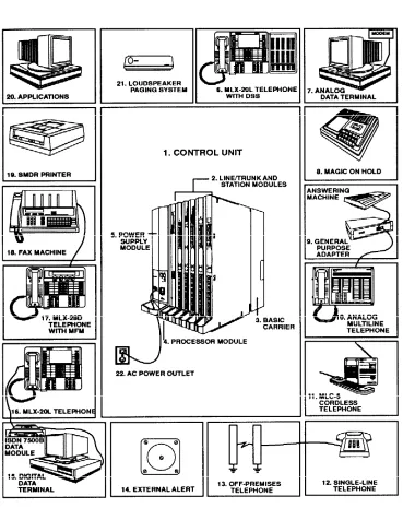
Figure 1-1 shows the components of the system. The numbered paragraphs following the figure correspond to the numbered items in the figure.
1. 2. 3. 4. 5. 6. 7. 8. 9. 10.
Control Unit. The backbone of the system, consisting of the basic and
expansion carriers, power supply module, processor module, and line/trunk and station modules. The control unit connects telephone company lines/trunks with stations such as telephones and adjuncts.
Line/Trunk and Station Modules. The components that connect
telephone company lines/trunks and terminal equipment such as
telephones, external alerts, and fax machines via jacks to the control unit.
Carrier (Basic). The component attached to the backboard used to hold
the modules needed for system operation. The basic carrier houses the processor module, power supply module, and up to five line/trunk and station modules. Each expansion carrier houses its own power supply and up to six additional line/trunk and/or station modules. One or two expansion carriers can be added.
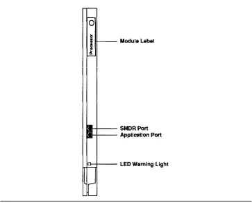
Processor Module. A miniature computer that controls most of the
system’s features, and supplies the system’s diagnostics. The processor provides two jacks, one for Station Message Detail Recording (SMDR) and the other for system programming and maintenance via a personal computer (PC).
Power Supply Module. The component that supplies DC power for the
modules and telephones (one power supply unit is needed per carrier). If the system’s power requirements exceed the capacity of the power supply, an auxiliary power supply unit can be added.
Direct Station Selector (DSS). A console that adds 50 buttons for
one-touch extension dialing to the MLX-20L or MLX-28D telephone and speeds call handling.
Analog Data Station. A data terminal such as a PC, printer, or optical
reader that connects, via a modem (for transmitting and receiving analog signals), to a 012 basic telephone module or a 008 off-premises
telephone (OPT) module. A data terminal can also be connected to an MLX telephone using an MFM or to an analog multiline telephone using a GPA.
Optional equipment that connects to the system
Magic On Hold®.
through a ground-start/loop-start (GS/LS) jack programmed for Music-on-Hold. (A customer-provided music source can be connected instead of Magic On Hold.)
General Purpose Adapter (GPA). An adapter used to connect a variety
of tip/ring (T/R) adjuncts to an analog multiline telephone (shown here with an answering machine).
Analog Multiline Telephone. A 34-button telephone with built-in
longer available for sale or lease) are compatible with the system: 5-button, 10-button, 34-button, and 34-button Deluxe.
11. MLC-5 Cordless Telephone. A cordless multiline telephone that connects to the control unit via an analog station jack.
12. Industry-Standard Single-Line Telephone. A touch-tone or rotary industry-standard telephone connected to the system via a 012 basic telephone module, a 008 OPT module, or an MLX telephone via an MFM. 13. Off-Premises Telephone (OPT). A single-line, touch-tone or rotary,
industry-standard telephone located in a different building from the control unit.
14. External Alert. Alerting devices such as balls, chimes, and strobe lights that connect to a jack on a 012 basic telephone module or a 008 OPT module, or to an MFM or SAA.
15. Digital Data Station. A data terminal such as a PC, printer, or optical reader that connects via a 7500B Data Module to a 008 MLX or 408 GS/LS-MLX module (Release 2.0 only) and that can also include an MLX telephone.
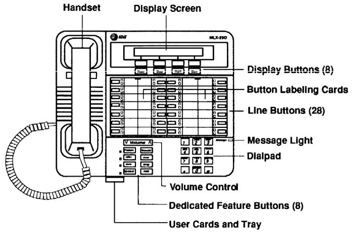
16. MLX-20L Telephone. An MLX telephone with 20 line buttons and a display with seven lines of 24 characters each. The MLX-20L telephone can be used as a system programming console. Other MLX telephones are as follows:
— MLX-10 Telephone: a 10-button MLX telephone without a two-Iine, 24-character display
— MLX-10D Telephone: a 10-button MLX telephone with a two-line 24-character display
17. MLX-28D Telephone with Multi-Function Module. An MLX telephone with 28 line buttons and a two-line, 24-character display.
A Multi-Function Module (MFM) is a circuit board mounted inside an MLX telephone that provides a jack to connect optional equipment such as answering machines, fax machines, external alerts, and modems to the telephone.
18. Fax. Industry-standard fax machines connected to the control unit via a jack on a 012 basic telephone module or a 008 OPT module, an MFM, or a GPA.
19. SMDR Printer. A printer for SMDR call records, connected via a RS-232 jack on the processor.
20. Applications. Software and hardware for the system that can be connected to the control unit to provide more functions.
22. AC Power Outlet. A dedicated 115-VAC wall outlet (not controlled by an on/off switch) that supplies power to the control unit.
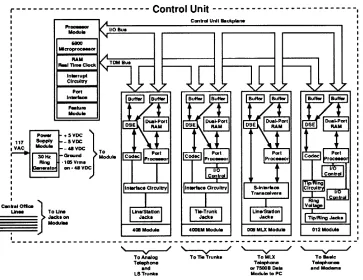
Functional Description
This section describes the functional units that make up the control unit, their relationships, and how signals are processed.
The control unit contains the following functional units:
■ Processor module
■ Power supply module
■ Carrier
■ Line/trunk and station modules
Functional Units
■ Input/Output Bus. The I/O bus contains a 16-bit address bus and an
8-bit data bus. The address bus selects the module that receives instructions from the 68000 microprocessor in the processor module. The microprocessor provides instructions to the port processors and DSEs through the 8-bit data bus.
■ Time-Division Multiplex Bus. The TDM bus connects the DSEs to allow
voice or data to flow in and out of the system. The TDM bus is parallel, 8 bits wide, and runs at 2.048 MHz (256 time slots x 8 kHz = 2.048 MHz). Each TDM cycle has 256 time slots for voice, data, tones, and clocks. The frame repetition rate is 8 kHz, providing a 64-kbps channel on each time slot (8-bit bus x 8 kHz = 64 kbps).
The built-in modem connects to the TDM bus; this permits access from a local or remote PC or workstation equipped with a 1200-bps modem, The TDM bus connects with the built-in diagnostics that enable the processor to read and write to dedicated TDM test slots.
The TDM bus carries analog signals encoded in Mu-Law 255 pulse code modulation (PCM) format for domestic use. The system provides a circuit-switched connection for transmission of digital data signals up to 64 kbps.
Digital Switching
Because the system is internally a digital system in a world of both analog and digital devices, it must accurately translate analog signals, Doing this involves signal conversion and switching. Codecs provide analog-to-digital and digital-to-analog conversion. The digitally encoded signals are routed from one interface port to another interface port by assigning source and destination information to specific time slots on the TDM bus. In this way, signals can be transmitted to one or several destinations and reconstructed at the original amplitude. The result is no signal loss during switching and transmission from one point to another.
The TDM bus allows many users to communicate over a common electrical connection because it is physically distributed across the backplane of the control unit and connects all line/trunk and station modules.
The processor uses the DSE to specify time slots for various functions, For example, during a conversation between station A and station B, a time slot is reserved for station A to transmit on and for station B to receive on. For example, station A talks on time slot 150 and listens on time slot 160. Station B talks on time slot 160 and listens on time slot 150.
A digital tone plant in the processor module provides touch-tone and call-progress signals to stations via time slots 0 to 39. Unlike other bus
Each module has a DSE to interface codecs or digital transceivers to the TDM bus. The actual digital switching occurs when the DSE is programmed by the system I/O bus to transmit data on or receive data from the TDM bus in specific time slots. In addition, the DSE can sum digital signals from designated TDM slots to provide conferencing for up to five parties.
Modes of Operation
NOTE:
Although the terms “line” and “trunk” technically refer to different facilities, the differentiation is not as clear as it once was, and the terms are usually treated as if they are interchangeable. A “line” traditionally connects a piece of equipment to a switching system; for example, it connects your home telephone to the local telephone company. A “trunk” connects one switching system to another switching system; for example, it connects a communications system like this (except for facilities line personal lines that pass transparently through the system) to the local telephone company’s central office (CO). Since the industry trend seems to be toward using “trunk” to refer to either facility, this standard is used in this section. The system can be programmed to operate in Key, Hybrid/PBX, or Behind Switch mode. The mode of operation determines the following:
■ The types of outside trunks that can be connected to the system
■ How telephone users access outside trunks ■ The types of system operator consoles allowed
■ The features available and how they work
The following sections describe each mode of operation, and Table 1-1 summarizes the modes.
Table 1-1. Modes of Operation Summary
Key
Trunks connected directly to control unit:
■ Ground-start
KF registration (FCC) No MF registration (FCC) Yes
PF registration (FCC) No
■ Loop-start Yes
■ PRI Yes
■ DSI Yes
Hybrid/PBX Behind Switch
No Yes Yes Yes Yes Yes
Table 1-1. - Continued
Key Hybrid/PBX Behind Switch
■ Tie
■ FX
■ WATS
■ DID
Yes Yes Yes No Yes Yes Yes Yes Yes Yes Yes No
Trunk pools No Yes No
No
ARS No Yes
ICOM buttons Yes No Yes
SA buttons No Yes No
Line buttons, that is, outside trunks assigned to buttons on telephone
Yes
Yes Yes
Shared trunks Yes (outside trunks only)
Yes (outside trunks and SA buttons)
Yes (outside trunks only)
Prime Lines No No Yes
Queued Call Console (QCC) No Yes No
Number of extensions:
■ <5(3
■ >50
Good Not recommended
Good
Good up to 80
KF or MF Good
Good
FCC registration KF or MF MF or PF
Key Mode
A Key system is the simplest way to provide users with more than one line from a single telephone. Older Key systems have telephones that look like single-line telephones except for a row of buttons, illuminated by incandescent lights when active, across the bottom. The leftmost button is labeled Hold, and the other buttons are labeled with telephone numbers.
When the communications system operates in Key mode, telephones are programmed with two kinds of buttons:
■ Line buttons (or keys) are associated with specific outside (telephone company) trunks. Line buttons allow users to see activity on other telephones, join conversations, and make and receive calls.
The Key mode of operation accommodates the following kinds of outside trunks:
■ Loop-start trunks, including basic lines, WATS, and foreign exchange (FX)
■ Ground-start trunks (only if registered as MF and if not strapped for Key mode, as described below) and emulated ground-start trunks on T1 facilities
■ DS1 facilities
■ Tie trunks and emulated tie trunks on T1 facilities
A standard Key system’s trunks are all loop-start. A loop-start trunk introduces a slight delay between the time the telephone company’s CO recognizes a call attempt and the time the call is processed. This delay is minimal and virtually unnoticeable. Most residence and small business telephones have loop-start trunks.
The communications system is configured for Key mode operation by system programming, depending on how the system is registered with the Federal Communications Commission (FCC), as described later in this section. If the system is modified for Key-only operation by the hardware strap in the processor module, no ground-start trunks can be connected to it. However, ground-start emulation on a T1 facility is allowed.
NOTE:
■ The default programmed mode is Key.
■ On initialization of a Release 1.0 system, all loop-start and ground-start trunk programming reverts to loop-ground-start. In Releases 1.1 and 2.0, if the system is programmed for Key mode, the strap is checked on initialization. If the strap is in (Key-only operation), all trunks revert to loop-start. If the strap is not in, any programmed designation of ground-start trunks is retained.
The following features are not available in Key mode:
■ Direct inward dialing (DID) trunks
■ Trunk pools
■ Automatic Route Selection (ARS)
■ QCCs and associated features
Line Access
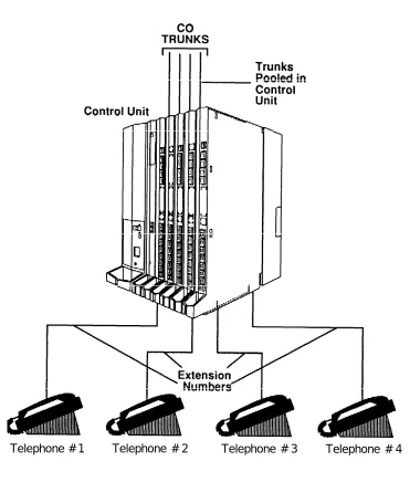
In Key mode (whether strapped and/or programmed), each outside line must be assigned to a line button on at least one telephone. As a result, the telephones most commonly used in Key mode are multibutton telephones. See Figure 1-3.
Telephone # 1 Telephone # 2 Telephone # 3
Figure 1-3. Lines Labeled for Key System Telephones
A user selects an outside line by pressing a personal line button-a button labeled with a telephone number. Upon hearing dial tone, the user can dial out. When a line is in use, the green LED goes on next to the corresponding
personal line button on any telephones that share that personal line.
The following types of ICOM buttons can be used to make and receive inside calls in Key mode:
■ An ICOM Ring button is used to make inside calls and to receive inside and outside calls transferred from another extension. When an
ICOM Ring button is used to make an inside call, the telephone at the destination extension rings once per ring cycle to indicate an inside call.
■ An ICOM Voice button is used to make inside calls and to receive inside and outside calls transferred from another extension. When an
ICOM Voice button is used to make an inside call, the person at the
destination extension hears the caller’s voice on the speakerphone after a beep, rather than ringing. (If he or she has a single-line telephone, does not have a speakerphone, or has disabled voice announcements, the telephone rings the same as if the call had been made on an
ICOM Ring button.)
■ An ICOM Originate Only button is used only to make inside calls. Neither inside nor outside calls are received on an ICOM Originate Only button. This type of button ensures that the user always has a button available to make or transfer a call, establish a conference call, answer a Call Waiting call, or pickup parked calls. The button can be
programmed for either voice or ring operation.
A combination of up to 10 ICOM Voice, ICOM Ring, and ICOM Originate Only buttons can be assigned to each telephone on buttons 1 through 10. The number of personal line buttons that can be assigned to a telephone is limited only by the number of trunks in the system and the number of buttons available on the telephone. See System Planning for button diagrams.
Key System Configurations
In Key mode, the system can be configured as a square, modified, or hybrid Key system, as described in the following sections. (The communications system does not distinguish among these configurations. )
In Key mode, the first eight trunks connected to the system are automatically assigned to the same eight buttons on all multiline telephones; all trunks are automatically assigned to each Direct-Line Console (DLC).
Square Key System
In a square Key system, every outside trunk in the system terminates on a personal line button on every telephone in the system.
Modified Key System
A Key system can be modified through system programming to provide trunk access for special business needs. For example, some business do not require every user to have access to a tie trunk, so the system can be programmed so that some telephones do not have access to all outside trunks.
Figure 1-4 shows an example of personal line button assignments in a modified Key system with two outside trunks and one tie trunk. Each trunk is not
assigned to a button on every telephone.
Figure 1-4. Lines Labeled for Modified Key System Telephones
Hybrid Key System
A hybrid Key system allows ground-start trunks to be connected directly to the system’s control unit. To program ground-start trunks in Key mode, the system may not be strapped for Key-only operation and must be registered with the FCC under an MF classification, as described later in this chapter, in the section FCC Registration. In this configuration, all outside trunks, including ground-start trunks, are assigned to personal line buttons on each telephone.
Key Mode Considerations
■ The multibutton telephones most commonly used in a Key system provide easy access to outside trunks. To get a dial tone, the user simply lifts the handset and an outside line is automatically selected.
Key mode has the flexibility to provide trunk access according to user needs. For example, tie trunks can be terminated on the telephones of only those users who need them.
The loop-start trunks traditionally associated with Key mode operation can cost less than the trunks used in the other modes.
Key systems are best suited to smaller businesses.
To take advantage of the features and functionality of the system, all users should have multibutton telephones when the system is operating in Key mode.
If the number of trunks connected to the system is larger than the number of buttons available on the DLC, Hybrid/PBX mode, which offers the QCC, may be more functional.
To make more efficient use of outside trunks by grouping them into pools for shared use, or to use ARS, the system must be programmed to operate for Hybrid/PBX operation.
Hybrid/PBX Mode
A private branch exchange (PBX) originally was a large switchboard installed at a customer’s office that functioned like a small, self-contained telephone company. The switchboard was manually operated, and the system operators physically connected calls by plugging cords into the board’s jacks. Today’s PBX is a processor in the communication system control unit programmed to connect both inside and outside calls on a single button. In Hybrid/PBX mode, this button is called a System Access button, and is labeled SA.
Although there is no longer a person handling cords, the communications system operating as a PBX still requires the user to request an outside trunk. A user simply dials a dial-out code (usually a 9) and the telephone number on an
SA button, and the system routes the call to an available outside trunk.
Thus, the major distinction of Hybrid/PBX mode, is that both inside and outside calls can be made on the same button.
The Hybrid/PBX mode of operation accommodates the following kinds of outside trunks:
■ Loop-start trunks, including basic lines, WATS, and FX
■ Ground-start trunks, including basic lines, WATS, and FX
■ DS1 facilities
■ Tie trunks and emulated tie trunks on T1 facilities
■ DID trunks
Since the outside trunks are pooled, outside numbers are not associated with individual telephones. When a pool is assigned to a line button during system programming, it is called a pool button. Users request specific trunk pools by dialing the trunk pool number (870-879) for the pool or by pressing a pool button, which gives one-touch access to a group of trunks.
Telephone # 1 Telephone # 2 Telephone # 3 Telephone # 4
Figure 1-5. Hybrid/PBX Mode
A feature commonly used in Hybrid/PBX mode is ARS. When an SA button is used to make an outside call and the ARS dial-out code is entered, the system selects the next available trunk from the type of pool that is most cost-effective for the call and gives the user access to that trunk.
The system automatically provides three types of trunk pools and assigns trunks to the appropriate pool type:
■ Loop-start trunks, by default, are assigned to pool number 70. This pool is called the loop-start pool or main pool.
■ Ground-start trunks, by default, are assigned to pool number 890. This pool is called the ground-start pool.
NOTE:
On initialization of a Release 1.0 system, all Imp-start and ground-start trunk programming reverts to Imp-ground-start. The ground-ground-start pool never has trunks assigned to it automatically, but must be
programmed after the ground-start ports are designated. In Releases 1.1 and 2.0, ground-start trunks are assigned to the ground-start pool on initialization, except in a system strapped for Key mode operation.
■ Tie trunks, by default, are assigned to pool number 891. This pool is called the tie pool.
Through system programming, the three automatically assigned pools can be rearranged and special-function or special-user pools can be created. For example, the main pool can be divided and smaller pools of loop-start trunks can be assigned to different groups of users.
Line Access
To make an outside call, the single-line telephone user dials a pool access or ARS dial-out code, and the system automatically selects an outside trunk. In addition, SA buttons on multiline telephones allow different kinds of calls to be made from the same buttom--outside calls on basic loop-start or ground-start trunks or on tie trunks or special service facilities such as WATS, and inside calls to other extensions in the system.
The following types of buttons can be assigned to multiline telephone users:
■ An SA Ring button is used to make and receive inside and outside calls.
When an SA Ring button is used to make an inside call, the telephone at the destination extension rings once per cycle to indicate an inside call.
■ An SA Voice button is used to make and receive inside and outside
■ An SA Originate Only button is used only to make inside and outside calls. Neither inside nor outside calls are received on an SA Originate
Only button. The purpose of this type of button is to ensure that the user
always has a button available to make or transfer a call, establish a conference call, answer a Call Waiting call, or pick Up parked calls. For inside calls, the button can be programmed for either voice or ring operation.
■ A Shared SA button is used to allow two or more users to answer each other’s calls, join conversations, or make or receive inside or outside calls on each other’s SA Ring or SA Voice buttons. In a Shared System Access arrangement, one extension is designated as the principal (or primary) extension. This extension is the telephone from which SA Ring,
SA Voice, and/or SA Originate Only buttons are assigned as Shared SA buttons on one or more telephones in the Shared System
Access arrangement.
Shared SA buttons are often provided to secretaries and their bosses,
as well as to others who work closely together, such as a customer service department. For inside calls, the button can be programmed for either voice or ring operation.
■ A pool button is used to make outside calls using a specific trunk pool, To make an outside call, the user presses the appropriate pool button— no dial-out code is necessary.
■ A personal line button is used to dedicate an outside trunk for use by
one or more telephones in the system. The personal line button is used to make and receive only outside calls. To make a call, the user presses the appropriate personal line button—no dial-out code is necessary. A combination of up to 10 SA Voice, SA Ring, SA Originate Only, and
Shared SA buttons can be assigned to each telephone (except for the QCC)
on buttons 1 through 10. See System Planning for button diagrams, The number of personal line buttons that can be assigned to a telephone is limited only by the number of trunks in the system and the number of buttons available on the telephone.
Queued Call Console
The type of system operator position typically used in Hybrid/PBX mode is the QCC, which allows calls to come to the operator one at a time. This is
especially useful when the number of outside trunks connected to the system control unit exceeds the number of buttons available on a DLC.
Hybrid/PBX Mode Considerations
■ Hybrid/PBX mode provides the most efficient use of outside trunks since they can be pooled and are more readily available to users. The ARS feature can be programmed for more cost-effective use of pools.
■ Hybrid/PBX mode provides greater functionality for single-line telephones than other modes of operation. The telephone user can make both inside and outside calls by accessing a pool of trunks.
■ The QCC, available only in Hybrid/PBX mode, ensures efficient call handling and is especially useful when the number of lines exceeds the number of buttons available on a DLC system operator position.
Behind Switch Mode
The system operates in the Behind Switch mode when the control unit is connected to (is “behind”) another system. The other system is referred to as the host, and can be either a PBX or Centrex service (a telephone company service that provides PBX-like capabilities but is housed at the CO).
Figure 1-6 illustrates a very simple Behind Switch configuration in which the outside trunks are connected to the host sys