61202217L1-1B June 2004
1202217L1 DC Version Including AC Mains Power Supply
1200218L1 HSSI DTE Interface Card
1200219L1 V.35 DTE Interface Card
1200284L1 Quad DSX-1 Interface Card
1200655L1 Quad Bridge Module
Spectrum is a registered trademark of Cabletron. Netview is a registered trademark of IBM.
901 Explorer Boulevard P.O. Box 140000 Huntsville, AL 35814-4000
(256) 963-8000 © 2004 ADTRAN, Inc.
This manual is arranged so you can quickly and easily find the information you need. The following is an overview of the contents of this manual:
• Chapter 1, Introduction, familiarizes you with fiber networks and T3SU 300 highlights and gives a brief explanation of the option cards that may be purchased for use with the T3SU 300.
• Chapter 2, Installation and Operation, describes the T3SU 300 connectors (pin assignments are given in Appendix A), provides installation instructions, and explains how to operate your T3SU 300 using the terminal interface.
• Chapter 3, Configuration, explains how to access the T3SU 300 Configuration menu, describes selections made in the Configuration menus, and provides a menu tree of Configuration options.
• Chapter 4, Status, describes each field of the Status menu.
• Chapter 5, Statistics, explains how to access statistical information for the T3SU 300 and describes each field.
• Chapter 6, Diagnostics, explains how to diagnose problems using loopback and BERT tests.
• Appendix A provides pinouts for the T3SU 300 connectors. • Appendix B contains product specifications.
Safety Instructions
When using your telephone equipment, please follow these basic safety precautions to reduce the risk of fire, electrical shock, or personal injury:
1. Do not use this product near water, such as a bathtub, wash bowl, kitchen sink, laundry tub, in a wet basement, or near a swimming pool.
2. Avoid using a telephone (other than a cordless-type) during an electrical storm. There is a remote risk of shock from lightning.
3. Do not use the telephone to report a gas leak in the vicinity of the leak.
4. Use only the power cord, power supply, and/or batteries indicated in the manual. Do not dispose of batteries in a fire. They may explode. Check with local codes for special disposal instructions.
Save These Important Safety Instructions
Cautions signify information that could prevent service interruption.
•
An affidavit is required to be given to the telephone company whenever digital
terminal equipment without encoded analog content and billing protection is used
to transmit digital signals containing encoded analog content which are intended
for eventual conversion into voiceband analog signals and transmitted on the
network.
•
The affidavit shall affirm that either no encoded analog content or billing
information is being transmitted or that the output of the device meets Part 68
encoded analog content or billing protection specifications.
•
End user/customer will be responsible for filing an affidavit with the local
exchange carrier when connecting unprotected customer premise equipment (CPE)
to 1.544 Mbps or subrate digital services.
For the work to be performed in the certified territory of ___________________
(telco name)
State of ________________
County of ________________
I, _______________________ (name), ____________________________________
(business address),
____________________ (telephone number) being duly sworn, state:
I have responsibility for the operation and maintenance of the terminal
equipment to be connected to 1.544 Mbps and/or ________ subrate digital
services. The terminal equipment to be connected complies with Part 68 of the
FCC rules except for the encoded analog content and billing protection
specifications. With respect to encoded analog content and billing protection:
( ) I attest that all operations associated with the establishment, maintenance, and
adjustment of the digital CPE with respect to analog content and encoded billing
protection information continuously complies with Part 68 of the FCC Rules and
Regulations.
( ) The digital CPE does not transmit digital signals containing encoded analog
content or billing information which is intended to be decoded within the
telecommunications network.
( ) The encoded analog content and billing protection is factory set and is not under
the control of the customer.
( ) A training course provided by the customer or authorized representative, using
training materials and instructions provided by the manufacturer/grantee of the
equipment used to encode analog signals; or
( ) An independent training course (e.g., trade school or technical institution)
recognized by the manufacturer/grantee of the equipment used to encode analog
signals; or
( ) In lieu of the preceding training requirements, the operator(s)/maintainer(s) is
(are) under the control of a supervisor trained in accordance with _________
(circle one) above.
I agree to provide ______________________ (telco’s name) with proper
documentation to demonstrate compliance with the information as provided in
the preceding paragraph, if so requested.
_________________________________Signature
_________________________________Title
_________________________________ Date
Transcribed and sworn to before me
This ________ day of _______________, _______
_________________________________
Notary Public
My commission expires:
1. This equipment complies with Part 68 of FCC rules. On the back of the equipment housing is a label showing the FCC registration number and ringer equivalence number (REN). If requested, provide this information to the telephone company. 2. If this equipment causes harm to the telephone network, the telephone company
may temporarily discontinue service. If possible, advance notification is given; otherwise, notification is given as soon as possible. The telephone company will advise the customer of the right to file a complaint with the FCC.
3. The telephone company may make changes in its facilities, equipment, operations, or procedures that could affect the proper operation of this
equipment. Advance notification and the opportunity to maintain uninterrupted service are given.
4. If experiencing difficulty with this equipment, please contact ADTRAN for repair and warranty information. The telephone company may require this equipment to be disconnected from the network until the problem is corrected or it is certain the equipment is not malfunctioning.
5. This unit contains no user-serviceable parts.
6. An FCC compliant telephone cord with a modular plug is provided with this equipment. This equipment is designed to be connected to the telephone network or premises wiring using an FCC compatible modular jack, which is Part 68 compliant.
7. The following information may be required when applying to the local telephone company for a dial-up line for the V.34 modem:
8. The REN is useful in determining the quantity of devices you may connect to your telephone line and still have all of those devices ring when your number is called. In most areas, the sum of the RENs of all devices should not exceed five. To be certain of the number of devices you may connect to your line as determined by the REN, call your telephone company to determine the maximum REN for your calling area.
Service Type REN FIC USOC
1.544 Mbps - SF 04DU9-BN 6.0N RJ-48C
1.544 Mbps - SF and B8ZS 04DU9-DN 6.0N RJ-48C
1.544 Mbps - ESF 04DU9-1KN 6.0N RJ-48C
This equipment has been tested and found to comply with the limits for a Class A digital device, pursuant to Part 15 of the FCC Rules. These limits are designed to provide reasonable protection against harmful interference when the equipment is operated in a commercial environment. This equipment generates, uses, and can radiate radio frequency energy and, if not installed and used in accordance with the instruction manual, may cause harmful interference to radio frequencies. Operation of this equipment in a residential area is likely to cause harmful interference in which case the user will be required to correct the interference at his own expense.
Shielded cables must be used with this unit to ensure compliance with
Class A FCC limits.
Notice: The Industry Canada label applied to the product (identified by the Industry Canada logo or the “IC:” in front of the certification/registration number) signifies that the Industry Canada technical specifications were met.
Notice: The Ringer Equivalence Number (REN) for this terminal equipment is supplied in the documentation or on the product labeling/markings. The REN assigned to each terminal device indicates the maximum number of terminals that can be connected to a telephone interface. The termination on an interface may consist of any combination of devices subject only to the requirement that the sum of the RENs of all the devices should not exceed five (5).
Canadian Emissions Requirements
ADTRAN will repair and return this product within 5 years from the date of shipment if it does not meet its published specifications or fails while in service. For detailed warranty, repair, and return information refer to the ADTRAN Equipment Warranty and Repair and Return Policy Procedure.
Return Material Authorization (RMA) is required prior to returning equipment to ADTRAN.
For service, RMA requests, or further information, contact one of the numbers listed at the end of this section.
LIMITED PRODUCT WARRANTY
ADTRAN warrants that for 5 years from the date of shipment to Customer, all products manufactured by ADTRAN will be free from defects in materials and workmanship. ADTRAN also warrants that products will conform to the applicable specifications and drawings for such products, as contained in the Product Manual or in ADTRAN’s internal specifications and drawings for such products (which may or may not be reflected in the Product Manual). This warranty only applies if Customer gives ADTRAN written notice of defects during the warranty period. Upon such notice, ADTRAN will, at its option, either repair or replace the defective item. If ADTRAN is unable, in a reasonable time, to repair or replace any equipment to a condition as warranted, Customer is entitled to a full refund of the purchase price upon return of the equipment to ADTRAN. This warranty applies only to the original purchaser and is not transferable without ADTRAN’s express written permission. This warranty becomes null and void if Customer modifies or alters the equipment in any way, other than as specifically authorized by ADTRAN.
EXCEPT FOR THE LIMITED WARRANTY DESCRIBED ABOVE, THE FOREGOING CONSTITUTES THE SOLE AND EXCLUSIVE REMEDY OF THE CUSTOMER AND THE EXCLUSIVE LIABILITY OF ADTRAN AND IS IN LIEU OF ANY AND ALL OTHER WARRANTIES (EXPRESSED OR IMPLIED). ADTRAN SPECIFICALLY DISCLAIMS ALL OTHER WARRANTIES, INCLUDING (WITHOUT LIMITATION), ALL WARRANTIES OF MERCHANTABILITY AND FITNESS FOR A PARTICULAR PURPOSE. SOME STATES DO NOT ALLOW THE EXCLUSION OF IMPLIED WARRANTIES, SO THIS EXCLUSION MAY NOT APPLY TO CUSTOMER.
ADTRAN will repair and return this product if within 5 years from the date of shipment the product does not meet its published specification or the product fails while in service.
A return material authorization (RMA) is required prior to returning equipment to ADTRAN. For service, RMA requests, training, or more information, use the contact information given below.
Repair and Return
If you determine that a repair is needed, please contact our Customer and Product Service (CAPS) department to have an RMA number issued. CAPS should also be contacted to obtain information regarding equipment currently in house or possible fees associated with repair.
Identify the RMA number clearly on the package (below address), and return to the following address:
CAPS Department (256) 963-8722
ADTRAN Customer and Product Service 901 Explorer Blvd. (East Tower)
Huntsville, Alabama 35806
sales support is needed, the ADTRAN Support web site provides a variety of support services such as a searchable knowledge base, latest product documentation,
application briefs, case studies, and a link to submit a question to an Applications Engineer. All of this, and more, is available at:
When needed, further pre-sales assistance is available by calling our Applications Engineering Department.
Post-Sale Support
Your reseller should serve as the first point of contact for support. If additional support is needed, the ADTRAN Support web site provides a variety of support services such as a searchable knowledge base, updated firmware releases, latest product documentation, service request ticket generation and trouble-shooting tools. All of this, and more, is available at:
When needed, further post-sales assistance is available by calling our Technical Support Center. Please have your unit serial number available when you call.
http://support.adtran.com
Applications Engineering (800) 615-1176
http://support.adtran.com
levels of installation and maintenance services which allow you to choose the kind of assistance you need. This support is available at:
For questions, call the ACES Help Desk.
Training
The Enterprise Network (EN) Technical Training Department offers training on our most popular products. These courses include overviews on product features and functions while covering applications of ADTRAN’s product lines. ADTRAN provides a variety of training options, including customized training and courses taught at our facilities or at your site. For more information about training, please contact your Territory Manager or the Enterprise Training Coordinator.
http://www.adtran.com/aces
ACES Help Desk (888) 874-ACES (2237)
Training Phone (800) 615-1176, ext. 7500
Training Fax (256) 963-6700
Product Overview . . . 25
T3 Overview . . . 26
SNMP . . . 26
TELNET . . . 27
Interface Option Cards . . . 27
HSSI Card . . . 28
V.35 Card . . . 28
Quad DSX-1 Card . . . 28
Ethernet Bridge Card . . . 29
Receiving Inspection . . . 31
ADTRAN Shipments Include . . . 31
Customer Provides . . . 32
Power Up . . . 32
Installing the Unit . . . 33
Rackmount Installation . . . 33
Desktop Installation . . . 34
Rear Panel . . . 34
DTE Port Interface Card Slots . . . 35
DTE Port 1 (HSSI Interface) . . . 36
Alarm Connector . . . 36
Auxiliary Port . . . 36
LAN Port . . . 36
DS3 Interface . . . 37
Front Panel . . . 37
Control Port . . . 37
LED Descriptions . . . 40
DS3 Network . . . 44
DS3 Framing . . . 45
Line Length . . . 45
DS3 Timing . . . 45
DS3 Scrambler . . . 46
Multiplexing Mode . . . 46
Data Link . . . 46
Timed Profiles . . . .55
System Management . . . 57
Local IP Address . . . .58
Subnet Mask . . . .58
Gateway IP Address . . . .58
Remote IP Address . . . .58
IP Security . . . .58
IP Hosts . . . .58
Management Port . . . .59
Modem Mode . . . .59
Modem Baud Rate . . . .59
Read Community Name . . . .59
Write Community Name . . . .59
Trap IP Addresses . . . .60
Trap Generation . . . .60
Password . . . .63
Control Port . . . .63
Unit ID . . . .64
Terminal Timeout . . . .64
Date/Time . . . .64
Alarm Relay . . . .64
Dialup Options . . . .64
Utilities . . . 67
Save Configuration . . . 68
Network Port . . . 69
DS3 Framing . . . .69
Network State . . . .70
Alarm State . . . .70
Data Link State . . . .71
Remote State . . . .71
DTE Ports. . . 72
Interface Type . . . .72
Port Status . . . .72
T1 Status . . . .73
Alarm History . . . 80
Performance Parameters . . . 82
Other Statistics . . . 85
DS3 . . . 95
DTE Ports 1-4 . . . 97
BERT Configuration . . . 107
Single Port Full T3 Bandwidth . . . 109
Point-to-Point Multiport Application . . . 110
Fractional T3 Carrier Application . . . 112
Remote SNMP Management Application . . . 114
Voice Application . . . 115
Appendix A
Pinouts . . . 117
Appendix B
Specifications Summary. . . 121
Appendix C
Acronyms/Abbreviations . . . 123
Figure 2-1. DC Power Connector . . . 33
Figure 2-2. T3SU 300 Rear View (AC Version) . . . 35
Figure 2-3. T3SU 300 Front Panel . . . 37
Figure 2-4. Terminal Main Menu . . . 38
Figure 3-1. Configuration Main Menu . . . 44
Figure 3-2. DS3 Network Configuration Menu . . . 45
Figure 3-3. DTE Ports Menu . . . 47
Figure 3-4. Port Configuration Menu (V.35 Interface Card) . . . 48
Figure 3-5. Port Configuration Menu (Quad DSX-1 Interface Card) . . . 52
Figure 3-6. Port Configuration Menu (Ethernet Bridge Interface Card) . . . 54
Figure 3-7. Timed Profiles Screen . . . 56
Figure 3-8. Example of a Profile Configuration Menu . . . 57
Figure 3-9. System Management Configuration Menu . . . 57
Figure 3-10. Trap Generation Menu . . . 60
Figure 3-11. Dialup Options Menu . . . 65
Figure 3-12. System Utilities Menu . . . 68
Figure 4-1. Status Menu . . . 69
Figure 4-2. Ethernet Bridge Status Menu . . . 76
Figure 5-1. Main Local Statistics Menu Screen . . . 80
Figure 5-2. Current Alarm Count Screen . . . 81
Figure 5-3. 24-Hour Alarm History Screen . . . 81
Figure 5-4. Quad DSX-1 24-Hour Alarm History . . . 82
Figure 5-5. Network Statistics Menu for Current 15-Minute Interval . . . 83
Figure 5-6. Network Port Statistics 24-Hour History Screen . . . 84
Figure 5-7. Network Port Statistics Menu (24-Hour Totals) . . . 85
Figure 5-8. Ethernet Bridge Statistics Menu Screen 1 . . . 86
Figure 5-9. Ethernet Bridge Statistics Menu Screen 2 . . . 88
Figure 5-10. Ethernet Bridge Statistics Menu Screen 3 . . . 90
Figure 6-1. Diagnostics Main Menu . . . 94
Figure 6-2. DS3 Diagnostics Menu . . . 95
Figure 6-3. DS3 Payload Loopback Test . . . 96
Figure 6-4. Line Loopback Test . . . 96
Figure 6-5. HSSI or V.35 Port Diagnostics Menu . . . 98
PRODUCT OVERVIEW
The T3SU 300 is a multiport DSU/CSU (data service unit/channel service unit) that provides access to T3 services. The unit provides a cost-effective, versatile approach for migrating T1 services to T3. The TDM (time division multiplexer) multiport design allows you to share the cost of a T3 line between multiple applications. This unit maximizes the use of T3 services, providing up to four data ports capable of transmitting and receiving high-capacity, real time data.
The T3SU 300 has a built-in HSSI (high speed serial interface) port along with three expansion slots which accept additional HSSI, V.35, Quad DSX-1, or Ethernet Bridge interface cards. The HSSI interfaces support rates between 75 kbps and 44.2 Mbps in 75 kbps increments. The high speed V.35 interface option supports rates up to 10 Mbps in increments of 75 kbps. The Quad DSX-1 interface card provides four DSX-1 lines. Each DSX-1 port supports rates up to 1.544 Mbps. The Ethernet Bridge interface card provides four auto-sensing 10/100 BaseT Ethernet ports.
Complete configuration, diagnostics, and performance monitoring are available through SNMP, Telnet, or a VT100 terminal interface. This connection can be made via Ethernet, a local EIA-232 link, or through the built-in V.34 modem. Advanced dial-out on trap capabilities through the built-in modem allow the T3SU 300 to contact remote hosts and alert them to DSX-3 network conditions (without dedicated management connections). The T3SU 300 is designed for either desktop use or installation in a 19-inch rack. The major features or the T3SU 300 are as follows:
• Full feature multiport T3 DSU/CSU
• Maximum of four user data ports: one integrated HSSI port and three additional slots for optional HSSI, high speed V.35, or Quad DSX-1 cards
• Automatic or manual remote configuration
• Embedded SNMP and Telnet management through 10BaseT Ethernet or SLIP/PPP
• Detailed performance monitoring for local and remote units • Simplified configuration through detailed VT100 terminal
menu structure
• Integrated V.34 modem for dial-up and dial-out access • Standard 5-year warranty
T3 OVERVIEW
T3 provides the same bandwidth as 28 T1s and is used to
interconnect high-speed bridges, routers, front-end processors, and data terminal equipment (DTE). T3 service plays a major role in Internet backbones and public organizations needing broad bandwidth for WAN (wide area network) connectivity.
SNMP
(LAN) port. The T3SU 300 supports the MIB-II standard, RFC 1213, and the ADTRAN Enterprise Specific MIB.
The term SNMP broadly refers to the message protocols used to exchange information between the network management system (NMS) and the managed devices, as well as to the structure of device management databases. SNMP has three basic components: Network Manager
Control programs that collect, control, and present data pertinent to the operation of the network devices. These programs reside on a network management station.
Agent
Control program that resides in every network device. This program responds to queries and commands from the network manager, returns requested information or invokes configuration changes initiated by the manager, and sends unsolicited traps to the manager.
MIB
Industry standard presentation of all status and configuration parameters supported by a network device.
TELNET
Telnet provides a password-protected, remote login facility to the T3SU 300 that allows a remote user to control the T3SU 300 through the terminal menus. Only one Telnet session may be active at a time.
INTERFACE OPTION CARDS
Optional interface cards may be purchased to equip the T3SU 300 with up to three additional ports. HSSI, V.35, and Quad DSX-1 interface cards are available.
HSSI Card
The optional HSSI card plugs into one of the three card slots on the rear of the T3SU 300. With optional HSSI cards installed, the total 44.2 Mbps bandwidth of the T3 can be divided among the total number of ports to provide multiple data channels over the T3. The total bandwidth of the T3 can be divided among the available ports in any fashion, as long as the divisions are on 75 kbps boundaries. The HSSI card can be hot inserted or swapped. When it is inserted in a slot on the rear panel and its faceplate is secured to the rear panel of the T3SU 300 with the integral thumb screws, a PCMCIA type connector on the card mates with a compatible connector on the main board of the T3SU 300. A standard 50-pin HSSI connector is then available for DTE connections. See the section DTE Port Interface Card Slots on page 35 for more information on installing option cards.
V.35 Card
The optional V.35 card plugs into the card slots on the rear of the T3SU 300 to provide a V.35-type DTE interface. Operation of the V.35 card is similar to that of the HSSI card except that the maximum bandwidth of the V.35 card is limited to 10 Mbps. Like the HSSI card, the V.35 card can be hot inserted or swapped, and it installs just as the HSSI card does. Instead of the standard HSSI connector, this card contains a standard 34-pin V.35 connector for DTE connections. See the section DTE Port Interface Card Slots on page 35 for more information on installing option cards.
Quad DSX-1 Card
network interface. Up to three cards may be installed into any of the T3SU 300 DTE port card slots.
Ethernet Bridge Card
The optional Quad DSX-1 interface card plugs into the card slots on the rear of the T3SU 300. This card provides four auto-sensing 10/ 100 BaseT Ethernet ports. The Bridge module provides LAN-to-LAN connectivity using bridging over the WAN. Additionally, this module acts as a LAN switch to provide Layer 2 Ethernet switching between each of the ports on the module. Up to three cards may be installed into any of the T3SU 300 DTE port card slots.
Even though the Quad DSX-1 interface card allows you to
trans-port T1 information, the T3SU 300 still operates the DS3 interface
in an unchannelized fashion. Therefore, your DS3 network
provid-er must supply you with an unchannelized, point-to-point DS3.
First generation T3SU’s (P/N 1200217L2 and P/N 1200217L4)
can only support a single Ethernet Bridge Module.
RECEIVING INSPECTION
Carefully inspect the T3SU 300 for any damage that may have occurred in shipment. If damage is suspected, file a claim immediately with the carrier and contact ADTRAN Technical Support (see the front section of this manual for contact
information). Keep the original shipping container to use for future shipment or verification of damage during shipment.
ADTRAN SHIPMENTS INCLUDE
The following items are included in ADTRAN shipments of the T3SU 300:
• T3SU 300 unit • T3SU 300 CD
• An 8-position modular to 8-position modular cable (part number: 3127004)
• An 8-position modular to DB-25 female connector (part number: 3196ADPT005)
• A 4-position modular to 4-position modular cable (part number: 3127014)
• Rubber feet for stand-alone use
Customer Provides
The customer provides an interface cable for each port used. Each cable should be either HSSI, V.35, or an 8-pin modular cable, depending on the interface type.
POWER UP
The AC version of the T3SU 300 is provided with a captive eight-foot power cord, terminated by a three-prong plug which connects to a grounded 115 VAC power receptacle.
A three-position terminal block which accommodates
12 to 26 AWG wire is located on the rear panel of the T3SU 300 DC version. The positive (+) and negative (-) terminals connect to a 24 to 48 VDC, 0.4A power source. Figure 2-1 on page 33 provides an illustration of the terminal block power connector, along with definitions for the three connector symbols.
The ADTRAN T3SU 300 MIB is available in the support section of
the ADTRAN web page at www.adtran.com.
Power to the AC version of the T3SU 300 must be provided from a
grounded 115 VAC, 60 Hz receptacle.
Figure 2-1. DC Power Connector The following UL requirements must be met during installation of the DC version of the T3SU 300:
1. The unit must be connected to a reliably grounded
-24 or -48 VDC source which is electrically isolated from the AC source.
2. The branch circuit overcurrent protection should be a fuse or circuit breaker rated 48 V, 15 A.
3. The unit should be installed in accordance with the requirements of NEC NFPA 70.
4. A readily accessible disconnect device that is suitably approved and rated should be incorporated in the fixed wiring.
INSTALLING THE UNIT
The T3SU 300 can be used as a desktop stand-alone device or mounted into a standard 19-inch equipment rack. The chassis can also be installed in a 23-inch equipment rack by using the 23-inch Rack Kit (P/N 1200171L1).
Rackmount Installation
Follow these steps to mount your unit into a rack:
1. Install the 19-inch or 23-inch rackmount flanges on each side of the T3SU 300 enclosure at one of the three available positions.
Symbol Definition
Frame ground.
+ Positive side of DC power source (usually ground).
2. After the flanges have been installed, position the T3SU 300 at the correct location within the rack and secure the mounting flanges to the mounting rails of the rack.
3. Make all network, DTE, and power connections to the rear of the unit. See Power Up on page 32 for more information on making the DC power connection.
4. Using the 8-position modular to DB-25 female connector and the 8-position modular to 8-position modular cable, connect a VT100 terminal device to the CONTROL interface jack on the front panel of the unit.
Desktop Installation
Follow these steps when using your T3SU 300 as a desktop unit: 1. Affix the four adhesive-backed rubber feet to the bottom of the
unit, one in each of the four corners. The feet should be placed approximately one inch from the front or back and one inch from the sides of the unit
2. Make all network, DTE, and power connections to the rear of the unit. See Power Up on page 32 for more information on making the DC power connection.
3. Using the 8-position modular to DB-25 female connector and the 8-position modular to 8-position modular cable, connect a VT100 terminal device to the CONTROL interface jack on the front panel of the unit.
REAR PANEL
port, a LAN port, and a DS3 interface. Pin assignments for connectors are given in Appendix A, Pinouts, on page 117. The T3SU 300 rear panel is shown in Figure 2-2.
Figure 2-2. T3SU 300 Rear View (AC Version)
DTE Port Interface Card Slots
The T3SU 300 rear panel has three card slots for the installation of optional interface cards. To insert cards, perform the following procedure:
1. Remove blank slot cover from the rear of the T3SU 300. 2. Slide the card into the corresponding rear slot until the card
panel is flush with the T3SU 300 chassis.
3. Push in thumbscrews and turn clockwise to secure the card and ensure proper connection to the main board of the T3SU 300.
DTE PORT 4
DJNTXBBFFLL BFLRVZDDJJNN
CHMSWAAEEKK AEKPUYCCHHMM
V.35 INTERFACE DTE PORT 3
HSSI INTERFACE
DTE PORT 2 DTE PORT 1 NC COM NO
AUX
LAN ALARM
RX IN TX OUT DS3 INTERFACE
Item Function
On/Off Switch On/Off control
115 VAC Connection Power connection (AC version)
DTE Ports 2-4 Interface option card slots
Alarm NC/NO relay contacts
DTE Port 1 Integral HSSI interface
Aux Telephone line connection for internal V.34 modem
LAN 10BaseT LAN connection
DTE Port 1 (HSSI Interface)
DTE port 1 is a built-in HSSI port that resides on the main board of the T3SU 300. The bandwidth of this port is configurable from 75 kbps to 44.2 Mbps in either 75 kbps or 3.16 Mbps increments. When a single application requires the full 44.2 Mbps of
bandwidth, the T3SU 300 does not have to be equipped with additional port cards.
Alarm Connector
The alarm connector is a three-position, screw-type terminal block that is connected to the three contacts of a Form C-type relay on the main board of the T3SU 300. This relay is activated any time the T3SU 300 detects an alarm condition on the T3 network interface. The alarm function can be disabled through the ALARM RELAY
selection of the CONFIGURATION menu.
Auxiliary Port
The auxiliary (AUX) port is an 8-pin modular jack located on the rear panel of the T3SU 300. The AUX port provides a telephone line (POTS) connection for the internal V.34 modem.
The T3SU 300 can be configured as a in host and also as a dial-out-on-TRAP device (meaning that the unit dials out to a specified host to report error conditions). Configure the modem parameters in the DIALUP OPTIONS menu under the SYSTEM MANAGEMENT
portion of the CONFIGURATION menu (CONFIGURATION-> SYSTEM MANAGEMENT -> DIALUP OPTIONS).
LAN Port
DS3 Interface
The DS3 network interface is a full-duplex circuit provided by two BNC coaxial cable connections. The receive data from the network is connected to the RXIN connector, while the transmit data from the T3SU 300 is connected to the TX OUT connector.
FRONT PANEL
The T3SU 300 faceplate is shown in Figure 2-3. Descriptions of each part of the front panel follow.
Figure 2-3. T3SU 300 Front Panel
Control Port
The T3SU 300 has an 8-pin modular jack labeled CONTROL. The control port provides connection to a VT100 EIA-232 compatible interface.
Establishing Terminal Connection
To control the T3SU 300 using a VT100 terminal, follow this procedure:
1. Configure the VT100 terminal for 57600 baud, 8-bit characters, no parity, and one stop bit.
2. Using the ADTRAN-provided terminal interface cable adapter, connect the DTE port of a terminal to the 8-pin modular jack labeled CONTROL on the front panel of the T3SU 300.
4. Enter the password. The factory default password is adtran (all lower-case). The MAIN menu appears. See Figure 2-4 on page
38.
5. Make selections by entering the number corresponding to the chosen parameter. Press ESC to return to the previous screen. End a terminal session by selecting LOGOUT from the MAIN
menu or by pressing Ctl-C at any time.
Figure 2-4. Terminal Main Menu Navigating Within the Menus
Navigate within the T3SU 300 terminal menus using the following procedures:
If you want to... Press...
select an item the number corresponding to your choice, and then press the Enter key.
scroll between screens within the same selection
the up and down arrow keys. Additional screens are available when UP or DOWN is displayed in the right-hand side of the menu.
scroll left and right within the same screen
Menus Available Status
This selection provides status information on the network and DTE ports. See Chapter 4, Status, on page 69 for more information. Statistics
This selection provides statistical information for the network and DTE ports. See Chapter 5, Statistics, on page 79 for more
information. Configuration
The CONFIGURATION menu is used to set network, DTE, and system management parameters. See Chapter 3, Configuration, on page 43 for more detailed information.
Diagnostics
The DIAGNOSTICS menu is used to perform loopback and BERT tests. See Chapter 6, Diagnostics, on page 93 for more detailed information.
Remote Login
The REMOTE LOGIN selection allows you to configure the remote T3SU 300. The remote unit’s password is required at login. The DATA LINK option (in the DS3 NETWORK CONFIGURATIONmenu) must be enabled in order to perform remote configuration. Logout
The LOGOUT selection ends the terminal session and logs out of the system. Password entry is required before a new session can begin.
return to the previous menu
the ESC key.
end the terminal session
Ctl-C.
LED Descriptions
The T3SU 300 has LED status indicators for remote access, the network port, and for each individual DTE port. These LEDs are identified as follows:
Remote Active
This LED is solid when a remote configuration session is taking place through a Telnet session or from the remote end T3SU 300. It flashes when the unit is being accessed locally through the front panel CONTROL port.
Network LEDs
In Service
This LED is active when a valid signal is being received on the DS3 interface.
In Test
This LED is active when the network interface has been put in loopback by the service provider.
Alarm
This LED is active when the DS3 receive signal contains framing errors, the yellow alarm is received from the far end unit, or other alarm messages are received from the network.
LOS
DTE Port LEDs
Status
This LED indicates the following conditions:
In Test
This LED is active when the DTE interface is in a loopback condition or is performing a BERT test.
TD
This LED is active when the T3SU 300 DTE port is transmitting data.
RD
This LED is active when the T3SU 300 DTE port is receiving data.
LED Condition
Off No option card is installed.
Flashing green Interface is available but not configured.
On green Interface is available and configured.
On red DTE fault condition (for HSSI interface, no clock from DTE).
The T3SU 300 can be configured locally and remotely. Local configuration is accomplished through a 10BaseT Ethernet connection, a SLIP/PPP port, or a VT100 terminal. Remote configuration can take place through the T3 datalink using a local T3SU 300.
The CONFIGURATION menu (see Figure 3-1 on page 44) consists of
submenus relating to specific interfaces or functions. This chapter describes each individual menu parameter. The information is organized by submenus into the following sections: DS3 NETWORK
Figure 3-1. Configuration Main Menu
DS3 NETWORK
Select 1 DS3 NETWORK to access the network configuration
parameters. Configure the T3SU 300 network settings to match the T3 signal received from the service provider. During remote configuration, this menu is read-only. The DS3 NETWORK CONFIGURATION menu is shown in Figure 3-2 on page 45.
Figure 3-2. DS3 Network Configuration Menu
DS3 Framing
Set the framing format to match the format of the receive signal at the network interface. C-BITPARITY and M13 framing formats are supported. Select AUTO to allow the interface to detect the framing type automatically.
Line Length
Set the line length to reflect the physical length of the DS3 network line. Set to LONG if the cabling distance exceeds 225 feet; set to SHORT if the distance is less than 225 feet.
DS3 Timing
DS3 Scrambler
Enable this option to scramble the DS3 payload data. This prevents certain transport equipment from falsely reporting alarms.
Multiplexing Mode
The MULTIPLEXING MODE menu allows you to select the DTE port bandwidth increment size. The increment size of Nx75 kbps allows the user to divide 588 blocks among the four ports. The increment size of Nx3.16 Mbps has 14 blocks available, and ports 2, 3, and 4 are disabled. Only port 1, the built-in HSSI port, is available in this mode. The Nx3.16 Mbps mode provides compatibility with Juniper and Cisco routers at below full-bandwidth rates. When the user switches the multiplexing mode, the system will reboot, causing service interruption. Loading default settings does not reset this option.
Data Link
Set to ENABLE to allow for remote configuration. When enabled, the T3SU 300 provides a channel between the local and the remote DSU for point-to-point remote configuration.
Remote Auto-Configuration
This feature allows one T3SU 300 (set to MASTER) to automatically relay its DTE port bandwidth configuration to a second unit (set to SLAVE). If desired, the feature can be disabled by either unit.
DTE PORTS
Configuration selections for the individual ports are described in the following section. A more in-depth description of TIMED PROFILES is on page 54.
Figure 3-3. DTE Ports Menu
Port Selections 1-4
Select DTE PORT 1, 2, 3, or 4 to access the port configuration parameters. Configure each DTE port to be compatible with the DTE equipment attached to it. PORT CONFIGURATIONmenu
examples are shown in Figure 3-4 on page 48, Figure 3-5 on page 52, and Figure 3-6 on page 54. Descriptions of the individual fields follow the illustration. The descriptions are listed in tables based on the DTE port interface type (HSSI, V.35, Quad DSX-1, or Ethernet Bridge).
• Table 3-1 on page 49 lists the menu fields available for HSSI and V.35 interfaces.
• Table 3-2 on page 50 lists the menu fields available for V.35 interfaces (in addition to those listed in Table 3-1).
• Table on page 54 lists the menu fields available for Ethernet Bridge interfaces.
Configuration Selections for HSSI and V.35 Interfaces
The configuration selections listed in Table 3-1 are available for HSSI and V.35 interfaces. Additional selections listed in Table 3-2 on page 50 apply only to V.35 interfaces.
Table 3-1. HSSI and V.35 Configuration Selections
Selection Description
INTERFACE TYPE This read-only status field shows the interface type of the selected port
(HSSI or V.35).
PORT STATUS This read-only status field displays one of the following messages to show the port status of the selected port:
INACTIVE: The port is installed, but idle. Activate a port through the
PORT STATE field of this menu.
ACTIVE: The port has been configured and is passing data.
WAITING: The port has been configured and is waiting for the DTE to issue the appropriate handshaking signals. For the HSSI interface, the terminal equipment available (TA) signal must be asserted by the DTE. For V.35, DTR is required if the TR field in this menu is set to IDLE WHEN OFF; otherwise, DTR is ignored.
ERROR: An error condition such as loss of transmit clock has occurred.
NOT INSTALLED: An interface card is not installed in the selected port. If a port is not installed, the remainder of the PORT CONFIGURATION
menu does not appear.
PORT STATE If a port is installed but not currently in use, set to DISABLED. Set to
ENABLED to activate an installed port.
NX75K BLOCKS This field determines the amount of bandwidth allocated to the selected port. For an HSSI interface, the selections are from 1-588 (yielding a bandwidth of 75.2 kbps to 44.2 Mbps). For a V.35 interface, the selections are from 1-140 (yielding a bandwidth of 75.2 kbps to 10.5 Mbps). Changes to this field do not take effect until APPLY SETTINGS is selected.
APPLY SETTINGS Select this field after making all configuration changes for the selected
port. The changes are then applied to the unit immediately. Applying the settings briefly affects all ports of the T3SU 300. You may cancel changes made to the current PORT CONFIGURATION menu by pressing the ESC key.
Note: Additional configuration selections are available for V.35 interfaces. These selections are listed in Table 3-2.
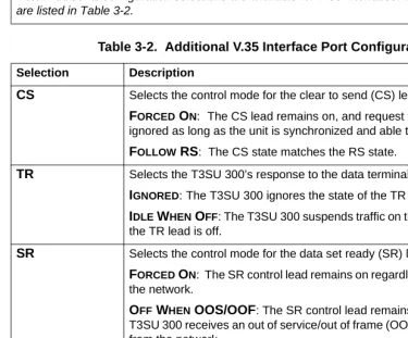
Table 3-2. Additional V.35 Interface Port Configuration Selections
Selection Description
CS Selects the control mode for the clear to send (CS) lead.
FORCED ON: The CS lead remains on, and request to send (RS) is ignored as long as the unit is synchronized and able to pass data.
FOLLOW RS: The CS state matches the RS state.
TR Selects the T3SU 300’s response to the data terminal ready (TR) lead.
IGNORED:The T3SU 300 ignores the state of the TR lead.
IDLE WHEN OFF: The T3SU 300 suspends traffic on the selected port if the TR lead is off.
SR Selects the control mode for the data set ready (SR) lead.
FORCED ON: The SR control lead remains on regardless of the state of the network.
OFF WHEN OOS/OOF: The SR control lead remains on unless the T3SU 300 receives an out of service/out of frame (OOS/OOF) condition from the network.
OFF WHEN TEST: The SR lead remains on except when the T3SU 300 is executing a test.
OFF WHEN OOS/OOF OR TEST: The SR lead remains on except when the unit receives an OOS/OOF condition from the network or when the unit is executing a test.
Table 3-1. HSSI and V.35 Configuration Selections (Continued)
Transmit Clock
Selects the source of the clock used to transfer data from the DTE to the T3SU 300. Use the following chart to determine your selection:
Configuration Selections for DSX-1 Interfaces
The configuration selections listed in Table 3-3 on page 52 are available for Quad DSX-1 interfaces. Separate selections can be made for each of the four DSX-1 ports of the card. This menu is shown in Figure 3-5 on page 52.
CD Selects the control mode for the carrier detect (CD) lead.
FORCED ON: The CD lead remains active at all times.
OFF WHEN OOS/OOF: The CD control lead remains on unless the T3SU 300 receives an OOS/OOF condition from the network.
TRANSMIT CLOCK See the following section for a description of this item.
Table 3-2. Additional V.35 Interface Port Configuration Selections (Continued)
Selection Description
Select... If...
NORMAL you want the transmit clock to be derived from the T3SU 300.
INVERT your DTE device cannot provide a transmit clock signal and data errors are present between your DTE and the T3SU 300.
EXTERNAL you are transmitting at high rates. This selection eliminates data errors caused by excessive delays in the DTE transmit clock receiver, transmit data driver, and cable length.
Figure 3-5. Port Configuration Menu (Quad DSX-1 Interface Card)
The Quad DSX-1 does not perform ESF to SF (D4) conversion
through the network. Therefore, both ends of the circuit must be
configured for the same framing type.
Table 3-3. DSX-1 Interface Port Configuration Selections
Selection Description
INTERFACE TYPE This read-only status field displays QUAD DSX-1, indicating that a Quad DSX-1 interface card is installed in the DTE Port card slot.
PORT STATUS This read-only status field displays INACTIVE, ACTIVE, WAITING, ERROR, OR NOT INSTALLED, indicating the current status of the DSX-1 interface.
UNALLOCATED 75K BLOCKS
Displays the amount of bandwidth (in 75k increments) not already allocated to any of the T3SU 300 DTE ports.
FRAMING Select the framing format for each individual DSX-1 interface. The
default setting is ESF. Select ESF if your DTE device is configured for Extended Superframe framing. Select D4 if your DTE device is configured for D4 framing. Select AUTO to allow the interface to detect the framing type (ESF or D4) automatically. When in AUTO mode, the selected interface toggles between ESF and D4 approximately every ten seconds until it detects valid framing.
Note: D4 is equivalent to superframe format (SF).
LINE CODING Set the line code for each individual DSX-1 interface to match the connected DTE device. Three choices are available: B8ZS, AMI, and AMI W/STUFFING (AMI coding with bit stuffing).
LINE LENGTH Set the line length for each DSX-1 interface according to the distance from the T3SU 300 to your DTE device. Set to 7.5 dB if the attached DTE device only supports DS-1 levels.
DSX-1 TIMING SOURCE
For each Quad DSX-1 card pair (the near- and far-end Quad DSX-1 cards), there must be only one source of timing. The available timing sources are described below:
DS3: The timing for both the near- and far-end Quad DSX-1 cards is derived from the DS3 interface. All DTE devices connected to the DSX-1 interfaces must be slave timed since both cards source the timing reference derived from the DS3. Both the near- and far-end units must be set to DS3.
REMOTE: The timing source for the Quad DSX-1 card is derived from the far-end Quad DSX-1 card. Use this mode if the far-end card has a DSX-1 TIMING SOURCE configuration of DSX-1 #1, DSX-1 #2, DSX-1 #3, or DSX-1 #4.
DSX-1 #X(x is 1,2,3, or 4): The timing source for the Quad DSX-1 pair is derived from one of the four DSX-1 interfaces. When configured in this manner, one of the DSX-1 interfaces is slaved to the DSX-1 interface from your DTE. The remaining three DSX-1 interfaces, if enabled, source the timing as derived from the slaved port. The far-end DSX-1 interface must be configured for REMOTE.
Note: If more than one Quad DSX-1 card is installed, each card can have a different timing source configuration.
APPLY SETTINGS Select this field after making all configuration changes for the selected port. The changes are then applied to the unit immediately.
Table 3-3. DSX-1 Interface Port Configuration Selections (Continued)
Configuration Selections for Ethernet Bridge Interfaces
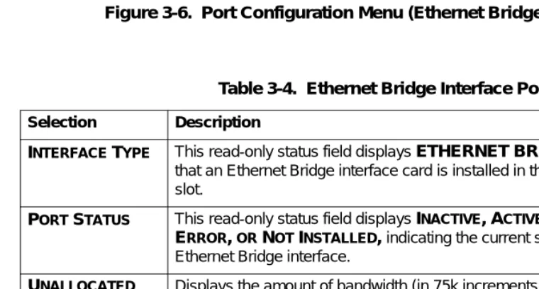
Figure 3-6 shows the Ethernet Bridge menu. Table lists the configuration selections available for the Ethernet Bridge interface.
Figure 3-6. Port Configuration Menu (Ethernet Bridge Interface Card)
Table 3-4. Ethernet Bridge Interface Port Configuration
Selection Description
INTERFACE TYPE This read-only status field displays ETHERNET BRIDGE, indicating that an Ethernet Bridge interface card is installed in the DTE Port card slot.
PORT STATUS This read-only status field displays INACTIVE, ACTIVE, WAITING, ERROR, OR NOT INSTALLED, indicating the current status of the Ethernet Bridge interface.
UNALLOCATED 75K BLOCKS
Displays the amount of bandwidth (in 75k increments) not already allocated to any of the T3SU 300 DTE ports.
PORT STATE If an Ethernet Bridge module is installed but not currently in use, set to
DISABLED. Set to ENABLED to activate the interface. Each of the four Ethernet ports can be individually activated with the PORT STATE option associated with that port.
Timed Profiles
Using this option, you can allocate bandwidth based on the time of day. For example, you can assign more bandwidth to the corporate LAN during business hours and more bandwidth to a backup machine in the evenings. The T3SU 300 can store two separate user profiles which have bandwidth selections for each of the four ports. See Figure 3-7 and Figure 3-8 on page 57.
SPEED Set the speed for each individual Ethernet interface. Three choices are
available: 10 BASET, 100 BASETX, and AUTO DETECT.
DUPLEX Set the duplex for each individual Ethernet interface. Three choices are available: FULL DUPLEX, HALF DUPLEX, and AUTO DETECT.
NX75K BLOCKS (1-588)
PORT BANDWIDTH
Set the amount of bandwidth allocated to the Ethernet Bridge port. The selections are from 1-588 (yielding a bandwidth of 75.2 kbps to 44.2 Mbps). The total PORT BANDWIDTH will automatically be calculated and displayed. Changes to this field do not take effect until
APPLY SETTINGS is selected.
APPLY SETTINGS Select this field after making all configuration changes for the selected port. The changes are then applied to the unit immediately.
Table 3-4. Ethernet Bridge Interface Port Configuration (Continued)
Selection Description
TIMED PROFILE
selections are only available if the
REMOTEAUTO-CONFIGURATION
selection is set to
MASTERon the near-end T3SU
Figure 3-7. Timed Profiles Screen Bandwidth Profiles 1 and 2
The PROFILE CONFIGURATION screens allow you to change the PORT STATE and NX75K BLOCKS options for HSSI and V.35 ports. See
page 49 for descriptions of these options. This screen also allows you to enable or disable each individual DSX-1 interface of a Quad DSX-1 card at the time of day specified in the given profile. Settings for all port types are assigned to the selected profile (1 or 2) and will apply whenever that profile is active. See Figure 3-8 on page 57. Profile Switch Time (1 and 2)
Enter the time that you want the profile to become active. Enter the time in military time (i.e., 00:00:00 = 12 AM). The profile remains active until one of the following occurs: (1) the other profile’s activation time comes about, or (2) the profile is disabled manually through the ACTIVE PROFILE selection.
Active Profile
Figure 3-8. Example of a Profile Configuration Menu
SYSTEM MANAGEMENT
The SYSTEM MANAGEMENT menu allows you to configure the T3SU 300 for management through SNMP, Telnet, or a VT100 interface. Embedded SNMP and Telnet are available through either a SLIP/ PPP or a 10BaseT Ethernet port. The SYSTEM MANAGEMENT CONFIGURATION menu is shown in Figure 3-9.
Local IP Address
Enter the T3SU 300 IP address. This IP address applies to the Ethernet or auxiliary port (when configured for PPP or SLIP). This address is available from the network administrator.
Subnet Mask
Enter the subnet mask of the T3SU 300. This address is available from the network administrator.
Gateway IP Address
Enter the gateway IP address of the T3SU 300. This address is necessary only if the T3SU 300 and the network manager are connected through a gateway node. If an IP packet is to be sent to a different network, the unit sends it to the gateway.
Remote IP Address
Enter the remote T3SU 300’s IP address to provide network management access through the local T3SU 300. See the section Remote SNMP Management Application on page 114 for more information.
IP Security
Enable or disable the IP Security option. If enabled, the unit accepts management commands and Telnet sessions from the IP addresses entered into the IP HOSTS fields.
IP Hosts
Management Port
Assign the management port to be either LAN, FDL (facility datalink), or the AUXPORT.
Modem Mode
Select the AUX port function for your application. The AUX port, located on the rear panel of the T3SU 300, provides a telephone line (POTS) for connecting to the internal V.34 modem. The modem interface can be configured for dial-in service in VT100, SLIP, and PPP modes. In addition, the T3SU 300 is capable of dial-out operation to report error conditions. All modem options can be configured in the DIALUP OPTIONS menu located on the SYSTEM MANAGEMENT CONFIGURATION screen. See Figure 3-9 on page 57. The DIALUP OPTIONS are described on page 64.
Selections for the MODEM MODE include dial-up options for VT100, PPP, and SLIP. If the MANAGEMENT PORToption is set to AUX PORT, the PPP and SLIP options are available.
Modem Baud Rate
Set the operating speed of the AUX port to match the connected device. The selections are 1200, 2400, 4800, 9600, 19200, and 38400 bps.
Read Community Name
Enter the authentication strings used for SNMP management. Match the T3SU 300 to the SNMP manager for read privileges.
Write Community Name
Trap IP Addresses
Enter up to five IP addresses of SNMP managers to which the T3SU 300 sends traps.
Trap Generation
This selection determines which trap types (if any) are generated by the unit. Use this menu (see Figure 3-10) to enable or disable NEAR END ALARM, FAR END ALARM, MIB II STANDARD, NETWORK TEST, DTE PORT, and QDSX ALARM trap types. See Table 3-5 on page 61 through Table 3-9 on page 63 for trap descriptions.
Table 3-5. Near End Alarm Trap Descriptions
Trap Type If ENABLED, this trap is sent... Red Alarm (LOS) when the unit detects a loss of signal.
Out of Frame (OOF) when the unit detects an out of frame condition.
Yellow Alarm (RAI) when the unit detects an incoming RAI signal.
Blue Alarm (AIS) when the unit detects an incoming AIS signal.
Idle Signal when the unit detects an incoming idle signal (1100) over the entire DS3 bandwidth.
Table 3-6. Far End Alarm Trap Descriptions
Trap Type If ENABLED, this trap is sent...
Red Alarm (LOS) when the unit receives indication from the far end unit through the FEAC channel that the far end unit has lost its receive signal.
Yellow Alarm (RAI) when the unit receives indication from the far end unit through the FEAC channel that the far end unit is receiving an RAI indication from the network.
Blue Alarm (AIS) when the unit receives indication from the far end unit through the FEAC channel that the far end unit is receiving an AIS indication from the network.
Idle Signal when the unit receives indication from the far end unit through the FEAC channel that the far end unit is receiving an idle signal (1100) over the entire DS3 payload.
Eqpt. Fail NSA when the unit receives indication from the network through the FEAC channel of a non-service-affecting failure in the network equipment.
Eqpt. Fail SA when the unit receives indication from the network through the FEAC channel of a service-affecting failure in the network equipment.
Com. Eqpt. Fail NSA when the unit receives indication from the network through the FEAC channel of a non-service-affecting failure in the network common equipment.
Table 3-7. MIB II Standard Trap Descriptions
Trap Type If ENABLED, this trap is sent... Cold Start when the unit is first powered on.
Link Up when the network recovers from a Link Down condition and data transmission is restored.
Link Down when a network condition prevents data transmission. This could be either an alarm or a network test.
Auth. Failure when an SNMP request is made with the wrong read or write community names.
Table 3-6. Far End Alarm Trap Descriptions (Continued)
Toggle All Traps
When activated, this entry allows you to toggle ALL alarms (previously described) between their disabled and enabled states.
Password
Set the password required at login (up to 32 characters). The default password is adtran (all lower case).
Control Port
Set the baud rate for the Control Port. The baud rate can be set to 57600 bps or 9600 bps.
Table 3-8. Network Trap Descriptions
Trap Type If ENABLED, this trap is sent...
Network Test In when the unit goes into a DS3 network test, either commanded locally or remotely.
Network Test Out when the unit is in a DS3 network test and the test is terminated.
Table 3-9. DTE Port Trap Description
Trap Type If ENABLED, this trap is sent...
Port Status Change when the unit detects a change in any of the four DTE ports. These traps may be generated when a DTE interface card is plugged in, a cord is removed, a port is reconfigured, a port goes into an error condition due to cabling problems, or a port goes into a test mode.
Table 3-10. Quad DSX Port Trap Description
Trap Type If ENABLED, this trap is sent...
Unit ID
Enter a name to identify the unit for management purposes.
Terminal Timeout
Set the amount of time the terminal or Telnet session can remain inactive before requiring re-entry of the password for access. This option can be disabled or set for 1 minute, 5 minutes, 15 minutes, 60 minutes, or one day.
Date/Time
Enter date and time information. Enter the time in military time (separated by colons). Enter the month, date, and year (separated by forward slashes).
Alarm Relay
Enable if the alarm terminal block (located on the rear of the unit) is connected to an audible alarm. If enabled, the alarm circuit is activated when a network alarm occurs.
Dialup Options
Figure 3-11. Dialup Options Menu Primary and Secondary Phone Numbers
When the T3SU 300 dials out to send a trap, it first dials the PRIMARY PHONE NUMBER. If the call is unsuccessful, it tries the SECONDARY PHONE NUMBER. Attempts between the two numbers continue until a call is established and the trap is reported (or until each number’s maximum for redial attempts is reached).
Initializing String
The AT command entered in this field is used to initialize the modem. Normally, this field should be left at the default setting (ATZ).
Dial String
The AT command entered in this field causes the modem to dial out. Normally, this field should be left at the default setting (ATDT).
Maximum Redial Attempts
Idle Timeout
Once a call is established and the trap messages are sent, the T3SU 300 remains online for the amount of seconds entered in this field. If the field is set to 0, the unit hangs up as soon as the trap is sent.
Connection Timeout
The T3SU 300 waits for a connection the amount of seconds entered in this field. Timing begins as soon as the dial command is issued. Pause Between Calls
The T3SU 300 waits the number of seconds entered in this field between redial attempts.
Dialout On Trap
Enable or disable the T3SU 300’s ability to dial out to report traps. When configured for DIALUP VT100, the unit reports error
conditions in plain ASCII with the following information: • The Unit ID value programmed in the Unit ID field of the
SYSTEM MANAGEMENT screen (see Figure 3-9 on page 57). • A trap code indicating the error condition (selected from the
TRAP GENERATION screen under SYSTEM MANAGEMENT)
• The date and time when the error was logged
When the MODEM MODE is configured for DIALUP PPP or DIALUP SLIP, the unit logs in to the PPP/SLIP host and reports the error conditions to the hosts designated under the TRAP IP ADDRESSES
(also found under SYSTEM MANAGEMENT). Answer on Ring
Enable or disable the T3SU 300’s ability to accept an incoming call. If enabled, incoming calls are automatically answered by the T3SU 300, allowing you to remotely perform management functions.
Hangup
Last Modem Response
This status field displays the last modem response to the T3SU 300. Possible responses include:
OK CONNECT BUSY ERROR NO DIALTONE NO CARRIER
UTILITIES
The UTILITIES menu allows you to view T3SU 300 system information (including self-test results), revert to default
configuration settings, update the flash software of the local unit, update the flash software of the far-end T3SU 300, or reset the unit. The SYSTEM UTILITIESmenu is shown in Figure 3-12 on page 68. Possible results for the self-test are listed in the following chart.
If the self-test results are... Then...
PASS the self-test was successful and the unit is ready to use.
BAD RAM DATA,
BAD RAM ADDRESS,
BAD CHECKSUM,
BAD BOOT SECTOR,
DS3F LOOPBACK FAILURE,
ARTE TERMINAL LOOPBACK FAILURE, or
ARTE INTERNAL LOOPBACK FAILURE
contact ADTRAN Technical Support. See Customer Service, Product
Support Information, and Training on
page 14.
Figure 3-12. System Utilities Menu
SAVE CONFIGURATION
The SAVE CONFIGURATION selection commits the current
View port status information by selecting 1 STATUSfrom the MAIN
menu. Information for the network port and the DTE ports is provided. The STATUS menu is shown in Figure 4-1.
Figure 4-1. Status Menu
NETWORK PORT
DS3 Framing
Network State
This field displays the current network state of the T3SU 300. Possible conditions are given in the following chart:
Alarm State
This field displays the current alarm condition of the T3SU 300. Possible conditions are given in the following chart:
Condition Description
Normal The T3SU 300 is ready to pass data.
Alarm The unit is currently receiving an alarm indication. See the ALARM STATE field in this menu to determine the alarm type.
In Test The unit is currently in test mode. The DIAGNOSTICS
menu provides information on test type.
Condition Description
Normal No alarms are currently being received.
Yellow The unit is transmitting a yellow alarm from the network. This alarm is a signal sent back toward the source of a failed transmit circuit. The X-bits (X1 and X2) are set to zero.
LOS (Red Alarm) The unit has lost the Rx signal.
Blue (AIS) The unit is receiving a blue alarm condition from the network. A blue alarm occurs when consecutive 1010s are received in the information bits. This indicates that there is a transmission fault located either at or upstream from the transmitting terminal.
OOF The unit detects an out of frame condition from the network.
Data Link State
This field displays the current state of the data link between the local and the remote T3SU 300s. Possible states are listed in the following chart:
Remote State
This field displays the current state of the remote link. Possible states are listed in the following chart:
Condition Description
Normal The local unit’s data link is in sync with the remote unit.
Disabled The DATA LINK option in the DS3 NETWORK CONFIGURATIONmenu is set to DISABLED. Down The local and remote units are not in sync.
Condition Description
Normal No alarms are currently being received.
RAI (Yellow Alarm)
The unit is transmitting a yellow alarm from the network. This alarm is a signal sent back toward the source of a failed transmit circuit. The X-bits (X1 and X2) are set to zero.
LOS (Red Alarm)
The unit has lost the Rx signal.
AIS (Blue Alarm)
The unit is receiving a blue alarm condition from the network. A blue alarm occurs when consecutive 1010s are received in the information bits. This indicates that there is a transmission fault located either at or upstream from the transmitting terminal.
OOF The unit detects an out of frame condition from the network.
Idle The unit detects an idle sequence from the network. Service is immediately available for use.
DTE PORTS
The following status information is available for DTE Ports 1-4.
Interface Type
The interface type of the port is shown in this field (HSSI, V.35, Quad DSX-1, or Ethernet Bridge).
Port Status
This field displays the current port status. Possible states are listed in the following chart:
Eqpt Fail (NSA) The network has signaled a non-service affecting equipment failure condition.
Com Eqpt Fail (NSA)
The network has signaled a non-service affecting common equipment failure condition.
Unknown The T3SU 300 is unable to determine the state of the network or the remote unit.
Condition Description
Condition Description
Inactive The port is installed, but idle. Activate a port through the
PORT STATE field of the DTE PORT CONFIGURATION
menu.
Active The port has been configured and is passing data.
Error An error condition such as loss of transmit clock has occurred.
T1 Status
This field displays the current status of the Quad DSX-1 interface card. Some conditions are given for each of the four individual ports, while others apply to the entire card. Possible states are listed in the following charts:
Waiting for DTE The port has been configured and is waiting for the DTE to issue the appropriate handshaking signals. For the HSSI interface, the terminal equipment available (TA) signal must be asserted by the DTE. For V.35, DTR is required if the TR field is set to IDLE WHEN OFF; otherwise, DTR is ignored. The TR field