ATLAS 800 SERIES
System Manual
1200780L1 ATLAS 830 System, AC 1200781L1 ATLAS 830 System, DC 1200321L1 ATLAS 890 System
1200322L1 ATLAS 890 System Controller Module 1200185L3 Quad T1/PRI Option Module
1200264L1 Quad E1/PRA Option Module 1200184L1 Quad Nx 56/64 Option Module 4200261Lx Quad USSI Option Module
1200186L2 Octal Basic Rate ISDN (U-Interface) Option Module 1200343L1 Octal Basic Rate ISDN (S/T Interface) Option Module 1200223L1 T3 Option Module
1200225L1 T3 Option Module with Drop and Insert Interface 4200773Lx Dual Video Option Module
1200771L1 NxT1 HSSI/V.35 Option Module 1200338L1 Octal FXS Option Module
1200221Lx 8,16,24,32 Channel Voice Compression Resource Modules 1200262L1 Nx 56/64 BONDing Resource Module
1200222L1 HDLC Resource Module 1200181L1 Modem-16 Resource Module 1200782L1 Modem-24 Resource Module 1200182L1 Async-232 Option Module
ATLAS 800 Series System Manual Trademarks
Trademarks
Any brand names and product names included in this manual are trademarks, registered trademarks, or trade names of their respective holders.
To the Holder of the Manual
The contents of this manual are current as of the date of publication. ADTRAN reserves the right to change the contents without prior notice. In no event will ADTRAN be liable for any special, incidental, or consequential damages or for commercial losses even if ADTRAN has been advised thereof as a result of issue of this publication.
About this Manual
This manual provides a complete description of the ATLAS 800 Series System and system software. The purpose of this manual is to provide the technician, system administrator, and manager with general and specific information related to the planning, installation, operation, and maintenance of the ATLAS 800 Series. This manual is arranged so that needed information can be quickly and easily found.
Viewing Menu information
The ATLAS 800 Series System menus are hierarchical in nature, and information about the menus is presented in the same succession. Main menus are numbered with submenus following. Also, hyperlinked menu trees are provided for the first two menu levels.
901 Explorer Boulevard P.O. Box 140000 Huntsville, AL 35814-4000
Phone: (256) 963-8000
© 2004 ADTRAN, Inc. All Rights Reserved.
ATLAS 800 Series System Manual Revision History
Revision History
Conventions
DocumentRevision
Date Description of Changes
A Aug 2002 Initial release.
B Jan 2004 Added Modem-24 Module.
Combined ATLAS 830 and ATLAS 890 into one manual. C Aug 2004 Corrections to menu selections.
D E F G
Notes provide additional useful information.
Cautions signify information that could prevent service interruption.
ATLAS 800 Series System Manual Safety Instructions
Safety Instructions
When using your telephone equipment, please follow these basic safety precautions to reduce the risk of fire, electrical shock, or personal injury:
1. Do not use this product near water, such as a bathtub, wash bowl, kitchen sink, laundry tub, in a wet basement, or near a swimming pool.
2. Avoid using a telephone (other than a cordless-type) during an electrical storm. There is a remote risk of shock from lightning.
3. Do not use the telephone to report a gas leak in the vicinity of the leak.
4. Use only the power cord, power supply, and/or batteries indicated in the manual. Do not dispose of batteries in a fire. They may explode. Check with local codes for special disposal instructions.
ATLAS 800 Series System Manual FCC-Required Information
FCC-Required Information
Product: ATLAS 830 (1200780L1/1200781L1) and ATLAS 890 (1200321L1)
FCC regulations require the following information be provided in this manual:
1. This equipment complies with Part 68 of FCC rules and requirements adopted by ACTA. Each of the registered modules has a label showing the FCC registration number and ringer equivalence number (REN). If requested, provide this information to the telephone company.
2. If this equipment causes harm to the telephone network, the telephone company may temporarily discontinue service. If possible, advance notification is given; otherwise, notification is given as soon as possible. The telephone company will advise the customer of the right to file a complaint with the FCC.
3. The telephone company may make changes in its facilities, equipment, operations, or procedures that could affect the proper operation of this equipment. Advance notification and the opportunity to maintain uninterrupted service are given.
4. If experiencing difficulty with this equipment, please contact ADTRAN for repair and warranty information. The telephone company may require this equipment to be disconnected from the network until the problem is corrected or it is certain the equipment is not malfunctioning.
5. This unit contains no user-serviceable parts.
6. An FCC compliant telephone cord with a modular plug is provided with this equipment. This equipment is designed to be connected to the telephone network or premises wiring using an FCC compatible modular jack, which is compliant with Part 68 and requirements adopted by ACTA.
7. The following information may be required when applying to the local telephone company for service:
8. The REN is useful in determining the quantity of devices you may connect to your telephone line and still have all of those devices ring when your number is called. In most areas, the sum of the RENs of all devices should not exceed five. To be certain of the number of devices you may connect to your line as determined by the REN, call your telephone company to determine the maximum REN for your calling area.
9. This equipment may not be used on coin service provided by the telephone company. Connection to party lines is subject to state tariffs. Contact your state public utility commission or corporation commission for information.
Part Number
Registration
Number Service Type REN/SOC FIC USOC
1200780L1 /
1200781L1 US: HDCDENAN1200780L1 1.544 Mbps - SF1.544 Mbps - SF and B8ZS 1.544 Mbps - ESF
1.544 Mbps - ESF and B8ZS
6.0 N 04DU9-BN 04DU9-DN 04DU9-1KN 04DU9-1SN RJ-48C 1200185L3 HDCUSA-31934-DE-N
1200771L1 US: HDCDENAN1200346L1
1200186L2 HDCUSA-32227-DE-N Basic Rate ISDN 6.0 N 02IS5 RJ-49C
ATLAS 800 Series System Manual FCC-Required Information
FCC Radio Frequency Interference Statement
This equipment has been tested and found to comply with the limits for a Class A digital device, pursuant to Part 15 of the FCC Rules. These limits are designed to provide reasonable protection against harmful interference when the equipment is operated in a commercial environment. This equipment generates, uses, and can radiate radio frequency energy and, if not installed and used in accordance with the
instruction manual, may cause harmful interference to radio frequencies. Operation of this equipment in a residential area is likely to cause harmful interference in which case the user will be required to correct the interference at his own expense.
Shielded cables must be used with this unit to ensure compliance with Class A FCC limits.
ATLAS 800 Series System Manual Affadavits
Affadavits
Affidavit Requirements Connection to Digital Services
• An affidavit is required to be given to the telephone company whenever digital terminal equipment without encoded analog content and billing protection is used to transmit digital signals containing encoded analog content which are intended for eventual conversion into voiceband analog signal and transmitted on the network.
• The affidavit shall affirm that either no encoded analog content or billing information is being transmitted or that the output of the device meets Part 68 encoded analog content or billing protection specifications.
• End user/customer will be responsible to file an affidavit with the local exchange carrier when connecting unprotected CPE to a 1.544 Mbps or subrate digital service.
ATLAS 800 Series System Manual Affadavits
Affidavit for Connection of Customer Premises Equipment to 1.544 Mbps and/or Subrate Digital Services
For the work to be performed in the certified territory of ___________________ (telco name)
State of ________________
County of ________________
I, _______________________ (name), ____________________________________ (business address),
____________________ (telephone number) being duly sworn, state:
( ) I have responsibility for the operation and maintenance of the terminal equipment to be connected to 1.544 Mbps and/or ________ subrate digital services. The terminal equipment to be connected complies with Part 68 of the FCC rules except for the encoded analog content and billing protection specifications. With respect to encoded analog content and billing protection:
( ) I attest that all operations associated with the establishment, maintenance, and adjustment of the digital CPE with respect to analog content and encoded billing protection information continuously complies with Part 68 of the FCC Rules and Regulations.
( ) The digital CPE does not transmit digital signals containing encoded analog content or billing information which is intended to be decoded within the telecommunications network.
( ) The encoded analog content and billing protection is factory set and is not under the control of the customer.
I attest that the operator(s)/maintainer(s) of the digital CPE responsible for the establishment, maintenance, and adjustment of the encoded analog content and billing information has (have) been trained to perform these functions by successfully having completed one of the following (check appropriate blocks):
( ) A. A training course provided by the manufacturer/grantee of the equipment used to encode analog signals; or
( ) B. A training course provided by the customer or authorized representative, using training materials and instructions provided by the manufacturer/grantee of the equipment used to encode analog signals; or
( ) C. An independent training course (e.g., trade school or technical institution) recognized by the manufacturer/grantee of the equipment used to encode analog signals; or
( ) D. In lieu of the preceding training requirements, the operator(s)/maintainer(s) is (are) under the control of a supervisor trained in accordance with _________ (circle one) above.
I agree to provide ______________________ (telco’s name) with proper documentation to demonstrate compliance with the information as provided in the preceding paragraph, if so requested.
_________________________________Signature
_________________________________Title
_________________________________ Date
Transcribed and sworn to before me
This ________ day of _______________, _______
_________________________________ Notary Public
ATLAS 800 Series System Manual Industry Canada Compliance Information
Industry Canada Compliance Information
Notice: The Industry Canada label applied to the product (identified by the Industry Canada logo or the “IC:” in front of the certification/registration number) signifies that the Industry Canada technical specifications were met.
Notice: The Ringer Equivalence Number (REN) for this terminal equipment is supplied in the
documentation or on the product labeling/markings. The REN assigned to each terminal device indicates the maximum number of terminals that can be connected to a telephone interface. The termination on an interface may consist of any combination of devices subject only to the requirement that the sum of the RENs of all the devices should not exceed five (5).
Canadian Emissions Requirements
This digital apparatus does not exceed the Class A limits for radio noise emissions from digital apparatus as set out in the interference-causing equipment standard entitled “Digital Apparatus,” ICES-003 of the Department of Communications.
ATLAS 800 Series System Manual Product Warranty
Product Warranty
ADTRAN will repair and return this product within the warranty period if it does not meet its published specifications or fails while in service. Warranty information can be found at www.adtran.com.
Product Registration
Registering your product helps ensure complete customer satisfaction. Please take time to register your products on line at www.adtran.com. Click Service and Support on the top of the page, and then click Product Registration under Support.
Customer Service, Product Support Information, and Training
ADTRAN will repair and return this product within the warranty period if it does not meet its published specifications or fails while in service. Warranty information can be found at www.adtran.com/warranty.
A return material authorization (RMA) is required prior to returning equipment to ADTRAN. For service, RMA requests, training, or more information, use the contact information given below.
Repair and Return
If you determine that a repair is needed, please contact our Customer and Product Service (CaPS) department to have an RMA number issued. CAPS should also be contacted to obtain information regarding equipment currently in house or possible fees associated with repair.
Identify the RMA number clearly on the package (below address), and return to the following address: CaPS Department (256) 963-8722
ADTRAN Customer and Product Service 901 Explorer Blvd. (East Tower)
ATLAS 800 Series System Manual Pre-Sales Inquiries and Applications Support
Pre-Sales Inquiries and Applications Support
Your reseller should serve as the first point of contact for support. If additional pre-sales support is needed, the ADTRAN Support web site provides a variety of support services such as a searchable knowledge base, latest product documentation, application briefs, case studies, and a link to submit a question to an Applications Engineer. All of this, and more, is available at:
When needed, further pre-sales assistance is available by calling our Applications Engineering Department.
Post-Sales Support
Your reseller should serve as the first point of contact for support. If additional support is needed, the ADTRAN Support web site provides a variety of support services such as a searchable knowledge base, updated firmware releases, latest product documentation, service request ticket generation and
trouble-shooting tools. All of this, and more, is available at:
When needed, further post-sales assistance is available by calling our Technical Support Center. Please have your unit serial number available when you call.
Installation and Maintenance Support
The ADTRAN Custom Extended Services (ACES) program offers multiple types and levels of installation and maintenance services which allow you to choose the kind of assistance you need. This support is available at:
For questions, call the ACES Help Desk.
http://support.adtran.com
Applications Engineering (800) 615-1176
http://support.adtran.com
Technical Support (888) 4ADTRAN
http://www.adtran.com/aces
ATLAS 800 Series System Manual Training
Training
The Enterprise Network (EN) Technical Training Department offers training on our most popular products. These courses include overviews on product features and functions while covering applications of
ADTRAN's product lines. ADTRAN provides a variety of training options, including customized training and courses taught at our facilities or at your site. For more information about training, please contact your Territory Manager or the Enterprise Training Coordinator.
Training Phone (800) 615-1176, ext. 7500 Training Fax (256) 963-6700
Table of Contents
Section 1
Engineering Guidelines . . . 14
Assists network designers in incorporating the ATLAS 800 Series System into
existing networks. Includes pinouts.
Section 2
System Description . . . 50
Provides managers with an overview of the ATLAS 800 Series System.
Section 3
Network Turnup Procedures . . . 57
Provides step-by-step instructions for installing and powering up the ATLAS 800
Series System.
Section 4
User Interface Guide . . . 66
Provides detailed descriptions of all menu options and configuration parameters for
the ATLAS 800 Series System.
Section 5
Detail Level Procedures (DLP) . . . 316
Provides the detailed instruction for performing various unit functions such as
upgrading firmware.
Section 6
System Event Log . . . 353
Explains System Event Log messages and describes configuration of the Event
Log.
Section 7
ADTRAN Utilities . . . 367
Provides instructions for configuring and using the ADTRAN utilities (Telnet,
VT100, Syslog, and TFTP).
SECTION 1
ENGINEERING GUIDELINES
Assists network designers in incorporating the ATLAS 800 Series System into existing networks. Includes pinouts.
Table of Contents
ATLAS 830 Description. . . 23
Equipment Dimensions . . . 23
Power Requirements (AC System) . . . 23
Power Requirements (DC System) . . . 23
ATLAS 830 Front Panel. . . 23
ACO Switch. . . 24
CRAFT Port. . . 24
Front Panel LEDs . . . 24
ATLAS 830 Rear Panel . . . 27
Admin Port . . . 28
10/100BaseT Connection . . . 29
Alarm Relay Connection . . . 29
MON . . . 29
T1/PRI Connections . . . 29
ATLAS 830 At-A-Glance Specifications . . . 30
ATLAS 890 Description. . . 33
Equipment Dimensions . . . 33
Power Requirements (AC System) . . . 33
Power Requirements (DC System) . . . 33
ATLAS 890 Front Panel. . . 34
ACO Switch. . . 34
CRAFT Port. . . 35
Front Panel LEDs . . . 35
ATLAS 890 Rear Panel . . . 38
Admin In Port . . . 38
10/100BaseT Connection . . . 39
Alarm Relay Connection . . . 40
External Input Connection. . . 40
ATLAS 890 At-A-Glance Specifications . . . 41
Option Module Pinouts . . . 43
Quad T1/PRI Option Module. . . 43
Quad E1/PRA Option Module . . . 44
Quad Nx 56/64 Option Module . . . 45
Quad USSI Option Module . . . 47
Octal BRI ISDN (U-Interface) Option Module . . . 50
Octal BRI ISDN (S/T Interface) Option Module . . . 50
Async-232 Option Module. . . 51
T3 Option Module . . . 51
T3 Drop and Insert Option Module . . . 52
ATLAS 800 Series System Manual Engineering Guidelines
List of Pinouts
Pinout 1. ATLAS 830 CRAFT Port (DB-9, female) . . . 24
Pinout 2. ATLAS 830 Admin Port (DB-9, female) . . . 28
Pinout 3. ATLAS 830 Ethernet (RJ-45) . . . 29
Pinout 4. ATLAS 830 Alarm Relay Connector. . . 29
Pinout 5. ATLAS 830 T1/PRI. . . 30
Pinout 6. ATLAS 890 CRAFT Port (RJ-48C). . . 35
Pinout 7. ATLAS 890 Admin In (RJ-48C) . . . 39
Pinout 8. ATLAS 890 Ethernet (RJ-48C). . . 39
Pinout 9. ATLAS 890 Alarm Relay Connector. . . 40
Pinout 10. ATLAS 890 External Relay Monitor Connector . . . 40
Pinout 11. Quad T1/PRI Module (USOC RJ-48C) . . . 43
Pinout 12. Quad E1/PRA Module (DB-15) . . . 44
Pinout 13. Quad E1/PRA Module (DB-62) . . . 44
Pinout 14. Quad Nx 56/64 Module (V.35 Winchester) . . . 45
Pinout 15. Quad Nx 56/64 Module (DB-78) . . . 45
Pinout 16. Quad USSI Module (DB-78). . . 47
Pinout 17. Quad USSI Module (EIA-530) . . . 48
Pinout 18. Quad USSI Module (RS-449/V.36) . . . 48
Pinout 19. Quad USSI Module (RS-232). . . 49
Pinout 20. Quad USSI Module (CCITT X.21 V.11) . . . 49
Pinout 21. Octal BRI (U-Interface) Module (RJ-45). . . 50
Pinout 22. Octal BRI (S/T Interface) Module (RJ-45) . . . 50
Pinout 23. Async-232 Option Module (DB-25) . . . 51
Pinout 24. T3 Module (BNC pair, female) . . . 51
Pinout 25. T3 Drop and Insert Module (BNC pair, female) . . . 52
Pinout 26. Dual Video Module (RS-366, DB-25) . . . 52
Pinout 27. Dual Video Module (V.35 Winchester) . . . 53
Pinout 28. Dual Video Module (EIA-530) . . . 54
Pinout 29. Dual Video Module (RS-449) . . . 54
Pinout 30. NxT1 HSSI/V.35 Module (RJ-48C) . . . 55
Pinout 31. NxT1 HSSI/V.35 Module (50-pin SCSI-II and V.35 Winchester) . . . 55
Pinout 32. Octal FXS Module (8-pin modular). . . 56
List of Figures
Figure 1. ATLAS 830 Front Panel Layout . . . 23Figure 2. ATLAS 830 Rear Panel . . . 28
Figure 3. ATLAS 890 Front Panel Layout . . . 34
Figure 4. ATLAS 890 Rear Panel . . . 38
List of Tables
Table 1. ATLAS 830 Front Panel LEDs’ Purpose . . . 24Table 2. ATLAS 830 LED Descriptions . . . 26
Table 3. ATLAS 830 Specifications . . . 30
Table 4. ATLAS 890 Front Panel LEDs’ Purpose . . . 35
Table 5. ATLAS 890 LED Description . . . 36
1.
ATLAS 830 DESCRIPTION
Equipment Dimensions
The ATLAS 830 is 17.5” W, 12.5” D, and 5.5” H and is equipped for table top use or for mounting in a 19-inch rack (mounting brackets are included in the shipment). All option modules fit inside the unit.
Power Requirements (AC System)
Regardless of the option modules configuration installed in the unit, the ATLAS 830 AC system has a maximum power consumption of 200 W and a maximum current draw of 3.5 A. With no option modules installed, the AC-powered ATLAS 830 has a power consumption of 50 W and a current draw of 0.64 A, maximum at 115 Vrms.
Power Requirements (DC System)
Regardless of the option modules configuration installed in the unit, the ATLAS 830 DC system has a maximum power consumption of 200 Wand a maximum current draw of 4.2 A at -48 VDC. With no option modules installed, the DC-powered ATLAS 830 has a power consumption of 45 W at -48 VDC.
2.
ATLAS 830 FRONT PANEL
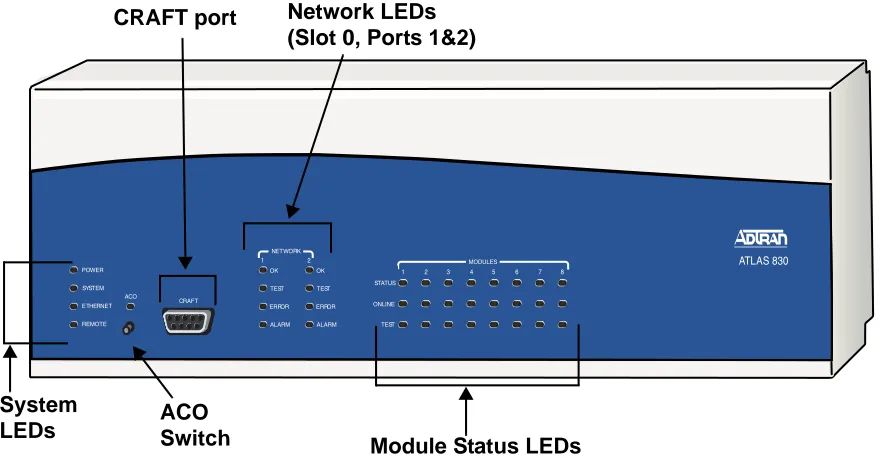
The ATLAS 830 front panel contains the Alarm Cut-off (ACO) switch, the CRAFT port, and status LEDs for the system (POWER, SYSTEM, ETHERNET, and REMOTE), network (NETWORK), and option mod-ule (MODULE). Figure 1 locates these features and Table 1 on page 17 further describes their functions.
ATLAS 830
1 2 3 4 5 6 7 8 STATUS ONLINE TEST MODULES 1 2 NETWORK TEST ERROR ALARM OK TEST ERROR ALARM OK POWER ETHERNET REMOTE SYSTEM CRAFT ACO ACO Switch
CRAFT port Network LEDs
(Slot 0, Ports 1&2)
Module Status LEDs System
ATLAS 800 Series System Manual ATLAS 830 Front Panel Engineering Guidelines
ACO Switch
The ACO switch clears the Alarm Relay (located on the rear panel) after an alarm condition has occurred. If an alarm condition is corrected and then reoccurs, the Alarm Relay activates again.
CRAFT Port
Use the CRAFT port (see Pinout 1) to configure the system via an EIA-232 connection.
Front Panel LEDs
With the ATLAS 830 powered-up, the front panel LEDs provide visual information about the status of the ATLAS 830 and any option modules that may be installed. Table 1 describes the purpose of the front panel LEDs, and Table 2 on page 19 provides information about the meaning of the LED colors.
Pinout 1. ATLAS 830 CRAFT Port (DB-9, female)
Pin Name Description
1 DCD Data Carrier Detect (output)—not connected
2 RD Receive Data (output)
3 TD Transmit Data (input)
4 DTR Data Terminal Ready (input)—not connected
5 SG Signal Ground
6 DSR Data Set Ready (output)—not connected
7 RTS Request to Send (input)—not connected
8 CTS Clear to Send (output)— not connected
9 RI Ring Indicate (output)—not connected
Table 1. ATLAS 830 Front Panel LEDs’ Purpose
LED Purpose
System Displays the status of the power supply, controller, and other system parameters for the ATLAS 830 (see Table 2 on page 19).
Power Indicates the status of the power supply.
System Indicates the status of the unit controller and other system parameters.
Ethernet Indicates the status of the Ethernet port.
ATLAS 800 Series System Manual ATLAS 830 Front Panel Engineering Guidelines
Network Displays the status of the two built-in T1/PRI interfaces on the rear panel of the unit. (These are referred to in the menus as Slot 0, Ports 1 and 2.)
OK Indicates that the network interface has passed self-test and is operating correctly.
Test Indicates that there is an active test on the T1/PRI interface.
Error Blinks to indicate the occurrence of error events such as clock slip
seconds (CSS), bipolar violations (BPV), errored seconds (ES), etc.
Alarm Indicates an active alarm condition on the T1/PRI interface.
ACO Indicates the status of the ACO switch.
Modules Displays by row the operational condition of each module installed in the option slots. All LEDs will be off if no option module is installed or configured.
Status Indicates the operational condition of modules installed in the option
slots.
Online Indicates whether the module is available for use or is currently in use. If
the module is manually taken offline, this LED is turned off.
Test Indicates that one or more ports within a module are in test.
ACO Clears the Alarm Relay connection located on the rear panel of the ATLAS 830.
CRAFT Allows the ATLAS 830 to connect to a computer using a VT100 terminal or terminal emulator.
Table 1. ATLAS 830 Front Panel LEDs’ Purpose (Continued)
ATLAS 800 Series System Manual ATLAS 830 Front Panel Engineering Guidelines
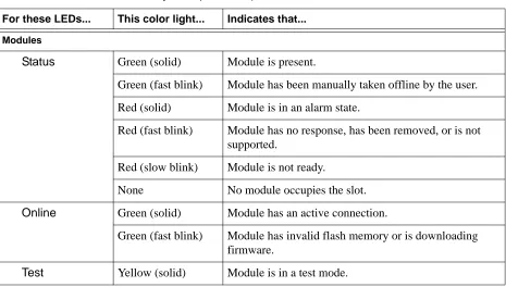
Table 2. ATLAS 830 LED Descriptions
For these LEDs... This color light... Indicates that... System
Power Red (solid) Power supply error condition or temperature alarm.
Green The unit is on and connected to a power source.
Off The unit is off.
System Green (solid) No diagnosed system faults were found.
Green (fast blink) System Controller is offline.
Yellow (fast blink) Flash download is in progress.
Yellow (solid) Self-test in progress.
Red (solid) Internal error condition.
Red (fast blink) Flash download or flash error condition.
Off Power is not currently supplied to the system or the power switch is in the off position.
Ethernet Green Link has been established.
Off Link has not been established.
Remote Yellow A user is logged into the unit via Telnet or VT100.
Off No users are logged into the unit.
ACO Yellow ACO switch is depressed.
Off ACO switch is not depressed.
Network
OK Green (solid) The network T1/PRI interface is operating normally with error-free operation.
Off The interface has experienced an alarm.
TEST Yellow (solid) The T1/PRI interface is in a test mode.
ERROR Red (blinking) Blinks with the occurrence of an error event including
BPV, CRC, and ES.
ALARM Red (solid) The T1/PRI interface is experiencing an alarm such as
ATLAS 800 Series System Manual ATLAS 830 Rear Panel Engineering Guidelines
3.
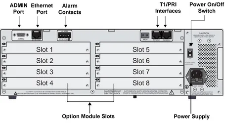
ATLAS 830 REAR PANEL
The ATLAS 830 rear panel (see Figure 2) contains an ADMIN port for connecting to a VT100 terminal (or terminal emulator) or modem, a 10/100BaseT interface for ETHERNET access, ALARM contacts, two built-in T1/PRI network interfaces (NTWK1 and NTWK2) and eight slots for housing option modules which provide a variety of additional resources and data ports. All slots are functionally identical. An optional redundant power supply may be installed in slots 7 and 8. In addition, the ON/OFF switch and
POWER SUPPLY are located on the rear panel.
Modules
Status Green (solid) Module is present.
Green (fast blink) Module has been manually taken offline by the user.
Red (solid) Module is in an alarm state.
Red (fast blink) Module has no response, has been removed, or is not supported.
Red (slow blink) Module is not ready.
None No module occupies the slot.
Online Green (solid) Module has an active connection.
Green (fast blink) Module has invalid flash memory or is downloading firmware.
Test Yellow (solid) Module is in a test mode.
Table 2. ATLAS 830 LED Descriptions (Continued)
ATLAS 800 Series System Manual ATLAS 830 Rear Panel Engineering Guidelines
Figure 2. ATLAS 830 Rear Panel
Admin Port
The ADMIN port (EIA-232, see Pinout 2 on page 21) connects to a computer or modem and provides the following functions:
• Accepts EIA-232 input from a PC or a modem for controlling the ATLAS 830. • Operates at 2400, 9600, 19200, or 38400 bps.
• Acts as input for either VT100 or PC control.
• Acts as an interface for flash memory software downloads using XMODEM.
Pinout 2. ATLAS 830 Admin Port (DB-9, female)
Pin Name Description Pin Name Description
1 DCD Data Carrier Detect (output) 6 DSR Data Set Ready (output
— not connected
2 RD Receive Data (output) 7 RTS Request to Send (input)
3 TD Transmit Data (input) 8 CTS Clear to Send (output)
4 DTR Data Terminal Ready (input) 9 RI Ring Indicate (output)
— not connected
5 SG Signal Ground
Slot 2
Slot 1
Slot 3
Slot 4
Slot 6
Slot 5
Slot 7
Slot 8
ADMIN Port
Ethernet Port
Alarm Contacts
T1/PRI Interfaces
Option Module Slots Power Supply
ATLAS 800 Series System Manual ATLAS 830 Rear Panel Engineering Guidelines
10/100BaseT Connection
The 10/100BaseT port (RJ-45) provides a 10/100BaseT Ethernet LAN connection, which is used for IP Routing, TFTP, SNMP, and Telnet connections (see Pinout 3).
Alarm Relay Connection
This connection alerts the user when a pre-selected alarm condition exists (see Pinout 4). The four-pin, removable terminal block connects with external wiring. Refer to DLP-11, Connecting the Alarm Contacts, on page 344 for detailed instructions. Clear the alarm condition by pressing the ACO switch located on the front panel of the ATLAS 830.
MON
The MON IN and OUT Bantam test jacks provide a bridged access jack for nonintrusive monitoring of the incoming T1. When connected to this jack, configure the test equipment for bridged termination.
T1/PRI Connections
Each of the T1/PRI ports, NTWK1 and NTWK2, uses a single eight-position modular jack to connect to the T1 or PRI circuit. Pinout 5 shows the pinout for this connector.
Pinout 3. ATLAS 830 Ethernet (RJ-45)
Pin Name Description
1 TX1 Transmit Positive
2 TX2 Transmit Negative
3 RX1 Receive Positive
4, 5 Unused —
6 RX2 Receive Negative
7, 8 Unused —
Pinout 4. ATLAS 830 Alarm Relay Connector
Pin Name Description
1 NC Normally closed, but opens when a pre-selected alarm condition is present.
2 NO Normally open, but closes when a pre-selected alarm condition is present.
3 COM Common connection between external circuitry and NC or NO terminal.
ATLAS 800 Series System Manual ATLAS 830 At-A-Glance Specifications Engineering Guidelines
4.
ATLAS 830
AT-A-GLANCE SPECIFICATIONS
Table 3 lists the specifications for the ATLAS 830 system.
Pinout 5. ATLAS 830 T1/PRI
Pin Name Description
1 RxData-Ring (R) Receive data from the network
2 RxData-Tip (T) Receive data from the network
3 Unused —
4 TxData-Ring (R1) Send data towards the network
5 TxData-Tip (T1) Send data towards the network
6,7,8 Unused —
Table 3. ATLAS 830 Specifications
Application Feature Specification
Operating Specifications
Temperature Operation: 0°C to 45°C
Storage: -40°C to 70°C
Relative Humidity To 95% noncondensing
TDM Applications
TDM bandwidth 46 Mbps Full duplex
ATLAS 800 Series System Manual ATLAS 830 At-A-Glance Specifications Engineering Guidelines
Switching Applications
ISDN signaling types National ISDN Lucent 5E
AT&T 4ESS (PRI Only)
Northern DMS-100 (Nortel Custom) Euro ISDN
T1 signaling types Loop-Start
Ground-Start E&M Wink E&M Immediate Feature Group D
DSP Features DTMF/MF tones support
Progress tone generation 32 available DSP channels 27 simultaneous dial tones
BRI Connections (recommended)
64 connections
PRI Connections (recommended)
345 B channels and 15 D channels
RBS T1 Connections (recommended)
120 DS0 connections
Table 3. ATLAS 830 Specifications (Continued)
ATLAS 800 Series System Manual ATLAS 830 At-A-Glance Specifications Engineering Guidelines
Frame Relay
Packet throughput 7900 pkts/sec (based on 64 byte size packets)
Management signaling interfaces
UNI (user and network) NNI
Management signaling types ANSI T1.617-D (Annex D) ITU-T Q.933-A (Annex A) LMI (Group of four) Auto
Encapsulation RFC 1490
PVC support 24 PVCs per packet endpoint (DS0 limited, 24 PVCs for T1).
992 is the limit of PVCs allowed in the unit.
Congestion control FECN / BECN
Discard eligible (DE)
Quality of service (QOS) Prioritization on a per-PVC basis
Testing (ADTRAN proprietary)
PVC loopback
Round trip delay measurement
SNMP support RFC 1315
PPP
Connection support 35 PPP connections to the internal router (not exceeding 3200 packets per second)
100 PPP connections to the internal router (requires HDLC Module and cannot exceed 3200 packets per second)
Authentication support PAP CHAP EAP
Keepalive support On/Off
Interface support Numbered interfaces Unnumbered interfaces
Table 3. ATLAS 830 Specifications (Continued)
ATLAS 800 Series System Manual ATLAS 890 Description Engineering Guidelines
5.
ATLAS 890 DESCRIPTION
Equipment Dimensions
The ATLAS 890 base unit is 17.08” W, 11.67” D, and 10.5” H and can be mounted in a 19-inch or 23-inch rack (mounting brackets are included in the shipment). All other equipment (option modules) fit inside the base unit.
Power Requirements (AC System)
Regardless of the option modules configuration installed in the base unit, the ATLAS 890 AC system has a maximum power consumption of 400 W and a maximum current draw of 7 A.
Power Requirements (DC System)
Regardless of the option modules configuration installed in the base unit, the ATLAS 890 DC system has a maximum power consumption of 325W and a maximum current draw of 8 A at -48 VDC.
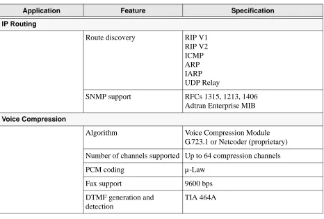
IP Routing
Route discovery RIP V1
RIP V2 ICMP ARP IARP UDP Relay
SNMP support RFCs 1315, 1213, 1406
Adtran Enterprise MIB
Voice Compression
Algorithm Voice Compression Module
G.723.1 or Netcoder (proprietary)
Number of channels supported Up to 64 compression channels
PCM coding µ-Law
Fax support 9600 bps
DTMF generation and detection
TIA 464A
Table 3. ATLAS 830 Specifications (Continued)
ATLAS 800 Series System Manual ATLAS 890 Front Panel Engineering Guidelines
6.
ATLAS 890
FRONT PANEL
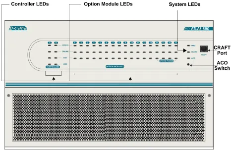
The front panel contains the Alarm Cut-off (ACO) switch, the CRAFT port, and the controller and option modules, and system (fans and alarm) status LEDS. The LEDs provide visual information about the
ATLAS 890 base unit and any option module that may be installed. Figure 3 identifies these features.
Figure 3. ATLAS 890 Front Panel Layout
ACO Switch
The ACO switch deactivates (clears) the Alarm Relay, located on the rear panel, after an alarm condition has occurred. If an alarm condition is corrected and then reoccurs, the Alarm Relay activates again.
Controller LEDs Option Module LEDs
ATLAS 800 Series System Manual ATLAS 890 Front Panel Engineering Guidelines
CRAFT Port
Use the CRAFT port (see Pinout 6) to connect to a computer to configure the system via an EIA-232 connection or to connect to a modem.
Front Panel LEDs
With the ATLAS 890 powered-up, the front panel LEDs provide visual information about the status of the unit and any option modules that may be installed. Table 4 describes the purpose of the front panel LEDs, and Table 5 on page 29 provides information about the meaning of the LED colors.
Pinout 6. ATLAS 890 CRAFT Port (RJ-48C)
Pin Name Description
1,2 Unused —
3 RXDATA Data received by the ATLAS 890
4 Unused —
5 TXDATA Data transmitted by the ATLAS 890
6,7 Unused —
8 Unused —
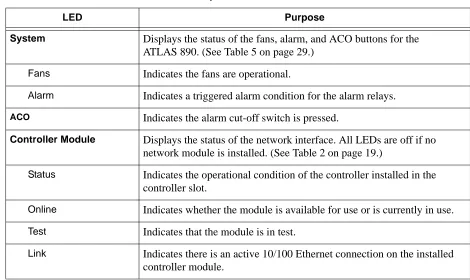
Table 4. ATLAS 890 Front Panel LEDs’ Purpose
LED Purpose
System Displays the status of the fans, alarm, and ACO buttons for the ATLAS 890. (See Table 5 on page 29.)
Fans Indicates the fans are operational.
Alarm Indicates a triggered alarm condition for the alarm relays.
ACO Indicates the alarm cut-off switch is pressed.
Controller Module Displays the status of the network interface. All LEDs are off if no network module is installed. (See Table 2 on page 19.)
Status Indicates the operational condition of the controller installed in the controller slot.
Online Indicates whether the module is available for use or is currently in use. Test Indicates that the module is in test.
ATLAS 800 Series System Manual ATLAS 890 Front Panel Engineering Guidelines
Option Module Displays by row the operational condition of each module installed in the option slots. All LEDs will be off if no option module is installed. (See Table 5 on page 29.)
Status Indicates the operational condition of modules installed in the option slots.
Online Indicates whether the module is available for use or is currently in use. If the module is manually taken offline, this LED is turned off.
Test Indicates that one or more ports within a module are in test.
Table 5. ATLAS 890 LED Description
For These Leds... This Color Light... Indicates That...
Fans Red (solid) Fan speed is too low or fan is disconnected.
Amber (solid) Fan speed is too high.
Green (solid) All fans are functioning properly.
Alarm Red (solid) A fan, external input, or power supply error has occurred. LED will remain red until the ACO button is pressed.
ACO Amber ACO button is being pressed.
Stand-by controller
Status Green (slow blink) Stand-by controller is present.
Online Green (solid) Stand-by controller operational for redundancy. Red (fast blink) Controller cannot automatically become the active
controller while the current active controller is installed.
Test N/A N/A
Link Green (solid) Ethernet link detected.
Table 4. ATLAS 890 Front Panel LEDs’ Purpose (Continued)
ATLAS 800 Series System Manual ATLAS 890 Front Panel Engineering Guidelines
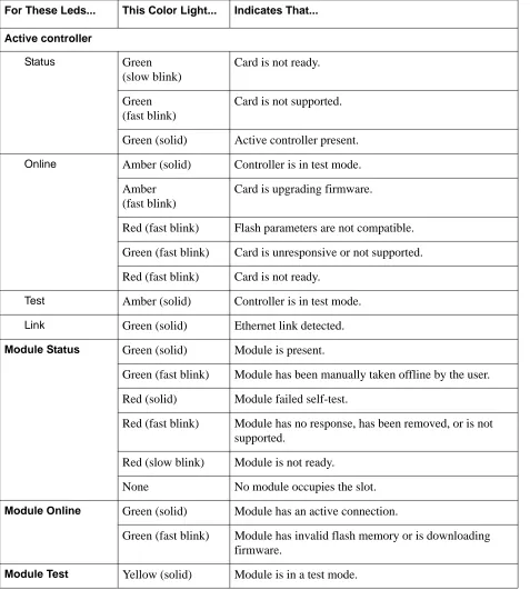
Active controller
Status Green
(slow blink)
Card is not ready.
Green (fast blink)
Card is not supported.
Green (solid) Active controller present.
Online Amber (solid) Controller is in test mode. Amber
(fast blink)
Card is upgrading firmware.
Red (fast blink) Flash parameters are not compatible.
Green (fast blink) Card is unresponsive or not supported.
Red (fast blink) Card is not ready.
Test Amber (solid) Controller is in test mode.
Link Green (solid) Ethernet link detected.
Module Status Green (solid) Module is present.
Green (fast blink) Module has been manually taken offline by the user.
Red (solid) Module failed self-test.
Red (fast blink) Module has no response, has been removed, or is not supported.
Red (slow blink) Module is not ready.
None No module occupies the slot.
Module Online Green (solid) Module has an active connection.
Green (fast blink) Module has invalid flash memory or is downloading firmware.
Module Test Yellow (solid) Module is in a test mode.
Table 5. ATLAS 890 LED Description (Continued)
ATLAS 800 Series System Manual ATLAS 890 Rear Panel Engineering Guidelines
7.
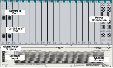
ATLAS 890 REAR PANEL
The ATLAS 890 rear panel contains 16 slots for housing option modules which provide a variety of additional resources and data ports (see Figure 4). All slots are functionally identical. The ATLAS 890 also contains two slots for housing controller modules and a single slot dedicated for power supply use only. The most common configuration is a fully redundant system with two system controllers and two power supplies. A fully redundant AC-powered ATLAS 890 provides 13 option slots. A fully redundant DC-powered ATLAS 890 provides 15 option slots.
Figure 4. ATLAS 890 Rear Panel
Admin In Port
The ADMIN IN port (EIA-232) connects to a computer or modem (see Pinout 7 on page 32). The control port input provides the following functions:
• Accepts EIA-232 input from a PC or a modem for controlling the ATLAS 890. • Operates at 2400, 9600, 19200, or 38400 bps.
• Acts as input for either VT100 or PC control.
• Acts as an interface for flash memory software downloads using XMODEM. Alarm Relay
Outputs
Power Connection ADMIN In
Port
10/100BaseT Port
External
Input Chassis
ATLAS 800 Series System Manual ATLAS 890 Rear Panel Engineering Guidelines
10/100BaseT Connection
The 10/100BaseT port (RJ-48C) provides a 10/100BaseT Ethernet LAN connection, which is used for IP Routing, TFTP, SNMP, and Telnet connections (see Pinout 8).
Pinout 7. ATLAS 890 Admin In (RJ-48C)
Pin Name Description
1 GND Ground—connected to unit chassis
2 RTS Request to send—low control
3 RxData Data received by the ATLAS 890
4 DTR Data terminal ready
5 TxDATA Data transmitted by the ATLAS 890
6 CD Carrier detect
7 Unused —
8 CTS Clear to send—flow control
Pinout 8. ATLAS 890 Ethernet (RJ-48C)
Pin Name Description
1 Tx1 Transmit Positive
2 Tx2 Transmit Negative
3 Rx1 Receive Positive
4, 5 Unused —
6 Rx2 Receive Negative
ATLAS 800 Series System Manual ATLAS 890 Rear Panel Engineering Guidelines
Alarm Relay Connection
This connection alerts the user when a pre-selected alarm condition exists. The four-pin, removable terminal block connects with external wiring (see Pinout 9). Refer to DLP-12, Connecting to the
ATLAS 890 External Input, for detailed instructions. Clear the alarm condition by pressing the ACO switch located on the front panel of the ATLAS 890.
External Input Connection
This connection alerts the user when a pre-selected external alarm condition exists and could be used, for example, to monitor a UPS with dry contacts or another ATLAS 890. The three-pin, removable terminal block connects with external wiring (see Pinout 10). Refer to DLP-12, Connecting to the ATLAS 890 External Input, for detailed instructions. Clear the alarm condition by pressing the ACO switch located on the ATLAS 890 front panel.
Pinout 9. ATLAS 890 Alarm Relay Connector
Pin Name Description
1 NC Normally closed, but opens when a preselected alarm condition is present.
2 NO Normally open, but closes when a preselected alarm condition is present.
3 COM Common connection between external circuitry and NC or NO terminal.
4 GND Chassis Ground
Pinout 10. ATLAS 890 External Relay Monitor Connector
Pin Name Description
1 Input Monitors for the presence or absence of -48 VDC
2 Vout -48 VDC @ 1 mA
ATLAS 800 Series System Manual ATLAS 890 At-A-Glance Specifications Engineering Guidelines
8.
ATLAS 890
AT-A-GLANCE SPECIFICATIONS
Table 6 lists the specifications for the ATLAS 890 system.
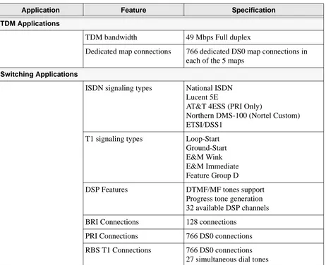
Table 6. ATLAS 890 Specifications
Application Feature Specification
TDM Applications
TDM bandwidth 49 Mbps Full duplex
Dedicated map connections 766 dedicated DS0 map connections in each of the 5 maps
Switching Applications
ISDN signaling types National ISDN Lucent 5E
AT&T 4ESS (PRI Only)
Northern DMS-100 (Nortel Custom) ETSI/DSS1
T1 signaling types Loop-Start
Ground-Start E&M Wink E&M Immediate Feature Group D
DSP Features DTMF/MF tones support
Progress tone generation 32 available DSP channels
BRI Connections 128 connections
PRI Connections 766 DS0 connections
ATLAS 800 Series System Manual ATLAS 890 At-A-Glance Specifications Engineering Guidelines
Frame Relay
Packet throughput 11,700 pkts/sec (64-1500 size packets)
Management signaling interfaces
UNI (user and network) NNI
Management signaling types ANSI T1.617-D (Annex D) ITU-T Q.933-A (Annex A) LMI (Group of four) Auto
Encapsulation RFC 1490
PVC support 990 PVCs per packet endpoint
Congestion control FECN / BECN
Discard eligible (DE)
Quality of service (QOS) Prioritization on a per-PVC basis
Testing (ADTRAN proprietary)
PVC loopback
Round trip delay measurement
SNMP support RFC 1315
PPP
Connection support 35 PPP connections to the internal router (not exceeding 11,700 packets per second)
100 PPP connections to the internal router (requires HDLC Module and cannot exceed 11,700 packets per second)
Authentication support PAP CHAP EAP
Keepalive support On/Off
Interface support Numbered interfaces Unnumbered interfaces
Table 6. ATLAS 890 Specifications (Continued)
ATLAS 800 Series System Manual Option Module Pinouts Engineering Guidelines
9.
OPTION MODULE PINOUTS
Pinouts for all of the available options modules are included here.
Quad T1/PRI Option Module
Each port of the Quad T1/PRI Option Module (P/N 1200185L3) uses a single, eight-position modular jack to connect to the T1 or PRI circuit (see Pinout 11).
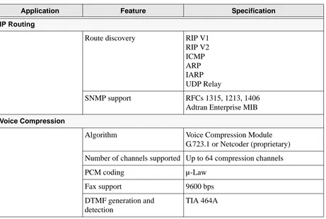
IP Routing
Route discovery RIP V1
RIP V2 ICMP ARP IARP UDP Relay
SNMP support RFCs 1315, 1213, 1406
Adtran Enterprise MIB
Voice Compression
Algorithm Voice Compression Module
G.723.1 or Netcoder (proprietary)
Number of channels supported Up to 64 compression channels
PCM coding µ-Law
Fax support 9600 bps
DTMF generation and detection
TIA 464A
Pinout 11. Quad T1/PRI Module (USOC RJ-48C)
Pin Name Description
1 RxData-Ring (R) Receive data from the network
2 RxData-Tip (T) Receive data from the network
3 Unused —
4 TxData-Ring (R1) Send data towards the network
5 TxData-Tip (T1) Send data towards the network
6,7,8 Unused —
Table 6. ATLAS 890 Specifications (Continued)
ATLAS 800 Series System Manual Option Module Pinouts Engineering Guidelines
Quad E1/PRA Option Module
Using the provided adapter cables, the DB-62 port of the Quad E1/PRA Option Module (P/N 1200264L1) supplies a DB-15 connection (see Pinout 12). See Pinout 13 for the DB-62 interface pinout.
Pinout 12. Quad E1/PRA Module (DB-15) Pin Name Description
1 RT Receive Tip
2 GND Ground
3 TT Transmit Tip
4 GND Ground
5 GND Ground
7 GND Ground
9 RR Receive Ring
11 TR Transmit Ring
Pinout 13. Quad E1/PRA Module (DB-62)
Pin Name Description Pin Name Description
11
1 Pins that are not identified are not used. P(1-4) indicates the Port
P4 TT Port 4 Transmit Tip 42 GND Ground
2 P4 TR Port 4 Transmit Ring 43 P4 RT Port 4 Receive Tip
3 GND Ground 44 P4 RR Port 4 Receive Ring
6 GND Ground 45 GND Ground
7 P3 TT Port 3 Transmit Tip 48 GND Ground
8 P3 TR Port 3 Transmit Ring 49 P3 RT Port 3 Receive Tip
9 GND Ground 50 P3 RR Port 3 Receive Ring
12 GND Ground 51 GND Ground
13 P2 TT Port 2 Transmit Tip 54 GND Ground
14 P2 TR Port 2 Transmit Ring 55 P2 RT Port 2 Receive Tip
15 GND Ground 56 P2 RR Port 2 Receive Ring
18 GND Ground 57 GND Ground
19 P1 TT Port 1 Transmit Tip 60 GND Ground
20 P1 TR Port 1 Transmit Ring 61 P1 RT Port 1 Receive Tip
ATLAS 800 Series System Manual Option Module Pinouts Engineering Guidelines
Quad Nx 56/64 Option Module
Using the provided adapter cables, each DB-78 port of the Quad Nx 56/64 Option Module
(P/N 1200184L1) supplies a V.35 Winchester-style connection (see Pinout 14). Pinout 15 shows the DB-78 interface pinout.
Pinout 14. Quad Nx 56/64 Module (V.35 Winchester)
Pin CCITT Description Pin CCITT Description
A 101 Protective ground (PG) V 115 RX clock (RC-A) to DTE
B 102 Signal ground (SG) X 115 RX clock (RC-B) to DTE
C 105 Request to send (RTS) from DTE
P 103 Transmitted data (TD-A) from DTE
D 106 Clear to send (CTS) to DTE S 103 Transmitted data (TD-B) from DTE
E 107 Data set ready (DSR) to DTE Y 114 TX clock (TC-A) to DTE
F 109 Received line signal detector (DCD) to DTE
AA 114 TX clock (TC-B) to DTE
H — Data terminal ready (DTR) from DTE
U 113 External TX clock (ETC-A) from DTE
J — Ring indicator (RI) W 113 External TX clock (ETC-B) from
DTE
R 104 Received data (RD-A) to DTE NN — Test mode (TM) to DTE
T 104 Received data (RD-B) to DTE
Pinout 15. Quad Nx 56/64 Module (DB-78)
Pin Signal Pin Signal
1 1 RXD-A 2/4 42 GND
2 RXD-B 2/4 43-48 Not used
3 RXC-A 2/4 49 MOD2
4 RXC-B 2/4 50 MOD0
5 TXD-A 2/4 51 EXT-TXC-A 1/3
6 TXD-B 2/4 52 DTR-B 1/3
7 TXC-A 2/4 53 DTR-A 1/3
8 TXC-B 2/4 54 DCD-B 1/3
ATLAS 800 Series System Manual Option Module Pinouts Engineering Guidelines
10 EXT-TXC-A 2/4 56 DSR-B/RI 1/3
11-17 Not used 57 DSR-A 1/3
18 GND 58 CTS-B 1/3
19 GND 59 CTS-A 1/3
20 CHASIS GND 60 CHASIS GND
21 CTS-A 2/4 61 GND
22 CST-B 2/4 62-68 Not used
23 DSR-A 2/4 69 MOD1
24 DSSR-B/RI 2/4 70 EXT-TXC-B 1/3
25 DCD-A 2/4 71 TXC-B 1/3
26 DCD-B 2/4 72 TXC-A 1/3
27 DTR-A 2/4 73 TXD-B 1/3
28 DTR-B 2/4 74 TXD-A 1/3
29-37 Not used 75 RXC-B 1/3
38 RTS-A 1/3 76 RXC-A 1/3
39 RTS-B 1/3 77 RXD-B 1/3
40 RTS-A 2/4 78 RXD-A 1/3
41 RTS-B 2/4
1 1/3 or 2/4 indicates the port on the Nx 56/64 Module
Pinout 15. Quad Nx 56/64 Module (DB-78) (Continued)
ATLAS 800 Series System Manual Option Module Pinouts Engineering Guidelines
Quad USSI Option Module
Pinouts 16 through 20 on the following pages describe the available interfaces for the Quad USSI Option Module (P/N 4200261Lx).
Pinout 16. Quad USSI Module (DB-78)
Pin Signal Description Pin Signal Description Pin Signal Description
11
1 1/3 or 2/4 indicates the port on the USSI Module
RXD-A 2/4 25 DCD-A 2/4 57 DSR-A 1/3
2 RXD-B 2/4 26 DCD-B 2/4 58 CTS-B 1/3
3 RXC-A 2/4 27 DTR-A 2/4 59 CTS-A 1/3
4 RXC-B 2/4 28 DTR-B 2/4 60 CHASIS GND
5 TXD-A 2/4 29-37 Not used 61 GND
6 TXD-B 2/4 38 RTS-A 1/3 62-68 Not used
7 TXC-A 2/4 39 RTS-B 1/3 69 MOD1
8 TXC-B 2/4 40 RTS-A 2/4 70 EXT-TXC-B 1/3
9 EXT-TXC-A 2/4 41 RTS-B 2/4 71 TXC-B 1/3
10 EXT-TXC-A 2/4 43-48 Not used 72 TXC-A 1/3
11-17 Not used 49 MOD2 73 TXD-B 1/3
18 GND 50 MOD0 74 TXD-A 1/3
19 GND 51 EXT-TXC-A 1/3 75 RXC-B 1/3
20 CHASIS GND 52 DTR-B 1/3 76 RXC-A 1/3
21 CTS-A 2/4 53 DTR-A 1/3 77 RXD-B 1/3
22 CST-B 2/4 54 DCD-B 1/3 78 RXD-A 1/3
23 DSR-A 2/4 55 DCD-A 1/3
ATLAS 800 Series System Manual Option Module Pinouts Engineering Guidelines
Pinout 17. Quad USSI Module (EIA-530)
Pin Signal Description Pin Signal Description Pin Signal Description
1 Shield (Ground) 10 Carrier Detect (B) 19 Request to Send (B)
2 Transmit Data (A) 11 Ext. Transmit Clock (B) 20 DTE Ready (A)
3 Received Data (A) 12 Transmit Clock (B) 21 Remote Loopback
4 Request to Send (A) 13 Clear to Send (B) 22 DCE Ready (B)
5 Clear to Send (A) 14 Transmit Data (B) 23 DTE Ready (B)
6 DCE Ready (A) 15 Transmit Clock (A) 24 Ext. Transmit Clock (A)
7 Signal Ground 16 Received Data (B) 25 Test Mode
8 Carrier Detect (A) 17 Receive Clock (A)
9 Received Clock (B) 18 Local Loopback
Pinout 18. Quad USSI Module (RS-449/V.36)
Pin Signal Description Pin Signal Description Pin Signal Description
1 Shield (Ground) 14 Remote Loopback 27 Clear to Send (B)
2 Signaling Rate Indicator
15 Ring Indicator 28 Terminal in Service
3 Not Used 16 Select Frequency 29 DCE Ready (B)
4 Transmit Data (A) 17 Ext. Transmit Clock (A) 30 DTE Ready (B)
5 Transmit Clock (A) 18 Test Mode 31 Carrier Detect (B)
6 Received Data (A) 19 Signal Ground 32 Select Standby
7 Request to Send (A) 20 Receive Common 33 Signal Quality
8 Receive Clock (A) 21 Not Used 34 New Signal
9 Clear to Send (A) 22 Transmit Data (B) 35 Ext. Transmit Clock (B)
10 Local Loopback 23 Transmit Clock (B) 36 Standby/Indicator
11 DCE Ready (A) 24 Receive Data (B) 37 Send Common
12 DTE Ready (A) 25 Request to Send (B)
ATLAS 800 Series System Manual Option Module Pinouts Engineering Guidelines
Pinout 19. Quad USSI Module (RS-232)
Pin Signal Description Pin Signal Description
1 Shield (Ground) 14 Sec. Transmit Data
2 Transmit Data 15 DCE Transmit Clock
3 Received Data 16 Sec. Received Data
4 Request to Send 17 Receive Signal Element Timing
5 Clear to Send 18 Not used
6 Data Set Ready 19 Sec. Request to Send
7 Signal Ground 20 Data Terminal Ready
8 Received Line Signal Detector 21 Signal Quality Detector
9 + Voltage 22 Ring Indicator
10 - Voltage 23 Data Signal Rate Selector
11 Not used 24 DTE Transmit Clock
12 Sec. Received Line Signal Indicator 25 Not used
13 Sec. Clear to Send
Pinout 20. Quad USSI Module (CCITT X.21 V.11)
Pin Signal Description Pin Signal Description
1 Shield (Ground) 8 Signal Ground
2 Transmit Data (A) 9 Transmit Data (B)
3 Request to Send (A) 10 Request to Send (B)
4 Received Data (A) 11 Received Data (B)
5 Carrier Detect (A) 12 Carrier Detect (B)
6 Transmit/Receive Clock (A) 13 Transmit/Received Clock (B)
7 Ext. Transmit Clock (A) 14 Ext. Transmit Clock (B)
ATLAS 800 Series System Manual Option Module Pinouts Engineering Guidelines
Octal BRI ISDN (U-Interface) Option Module
Each port of the Octal BRI ISDN (U-Interface) Option Module (P/N 1200186L2) uses a single RJ-45 jack to connect to a standard BRI U interface circuit (see Pinout 21).
Octal BRI ISDN (S/T Interface) Option Module
Each port of the Octal BRI ISDN (S/T Interface) Option Module uses a single RJ-45 jack to connect to a standard BRI S/T interface circuit (see Pinout 22). The Octal BRI ISDN (S/T Interface) Option Module is only available for use in NT mode (User Term) applications.
Pinout 21. Octal BRI (U-Interface) Module (RJ-45)
Pin Name Description
1, 2, 3, 6, 7, 8 Unused —
4 Ring Ring to and from the Network Interface
5 Tip Tip to and from the Network Interface
Pinout 22. Octal BRI (S/T Interface) Module (RJ-45)
Pin Name Description
1, 2, 7, 8 Unused —
3, 6 Receive Receive for User Term (NT Mode)
ATLAS 800 Series System Manual Option Module Pinouts Engineering Guidelines
Async-232 Option Module
Using the provided adapter cables, each Async-232 Option Module (P/N 1200182L1) interface provides a DB-25 (see Pinout 23).
T3 Option Module
Using the provided RG 59, 75-Ohm cables (P/N 3125I054), each T3 Option Module (P/N 1200223L1) provides BNC connectors for transmit and receive connections (see Pinout 24).
Pinout 23. Async-232 Option Module (DB-25)
Pin Name Description
1 Shield Shielded ground connection
2 TXD Transmit data from DTE
3 RXD Receive data to DTE
4 RTS Request to send from DTE
5 CTS Clear to send to DTE
6 DSR Data set ready to DTE
7 GND Ground
8 DCD Data carrier detect to DTE
9—19, 21, 23—25 Unused n/a
20 DTR Data terminal ready from DTE
22 RI Ring indicator to DTE
Pinout 24. T3 Module (BNC pair, female)
Name Description
RX IN Receive data from the network, 75 ohms ± 5%, unbalanced
ATLAS 800 Series System Manual Option Module Pinouts Engineering Guidelines
T3 Drop and Insert Option Module
Using the provided RG-59, 75-Ohm cables (P/N 3125I054), each T3 Drop and Insert Option Module (P/N 1200225L1) provides BNC connectors for primary and secondary transmit and receive connections (see Pinout 25).
Dual Video Option Module
The Dual Video Option Module (P/N 4200773Lx) provides a standard RS-366 dialing interface (DB-25) and a DTE interface (provided through adapter cables). Pinout 26 shows the RS-366 dialing interface and Pinouts 27 through 29 on the following pages show pinouts for the other available interfaces.
Pinout 25. T3 Drop and Insert Module (BNC pair, female)
Name Description
Primary RX IN Primary receive data from the network, 75 ohms ± 5%, unbalanced
Primary TX OUT Primary transmit data to the network, 75 ohms ± 5%, unbalanced
Secondary RX IN Secondary receive data from the network, 75 ohms ± 5%, unbalanced
Secondary TX OUT Secondary transmit data to the network, 75 ohms ± 5%, unbalanced
Pinout 26. Dual Video Module (RS-366, DB-25)
Pin Name Description Pin Name Description
1 Shield Shielded Ground Connection 14 NB1 Digit Signal Circuit 1
2 DPR Digit Present 15 NB2 Digit Signal Circuit 2
3 ACR Abandon Call and Retry 16 NB4 Digit Signal Circuit 4
4 CRQ Call Request 17 NB8 Digit Signal Circuit 8
5 PND Present Next Digit 18 RC Receive Common
6 PWI Power Indication 19 SC Send Common
7 SG Signal Ground 20-21 Unused n/a
8-12 Unused n/a 22 DLO Data Link Occupied
ATLAS 800 Series System Manual Option Module Pinouts Engineering Guidelines
Pinout 27. Dual Video Module (V.35 Winchester)
Pin CCITT Name Description
A 101 PG Protective ground
B 102 SG Signal ground
C 105 RTS Request to send from DTE
D 106 CTS Clear to send to DTE
E 107 DSR Data set ready to DTE
F 109 DCD Received line signal detector to DTE
H — DTR Data terminal ready from DTE
J — RI Ring indicator
R 104 RD-A Received data to DTE
T 104 RD-B Received data to DTE
V 115 RC-A RX clock to DTE
X 115 RC-B RX clock to DTE
P 103 TD-A Transmitted data from DTE
S 103 TD-B Transmitted data from DTE
Y 114 TC-A TX clock to DTE
AA 114 TC-B TX clock to DTE
U 113 ETC-A External TX clock from DTE
W 113 ETC-B External TX clock from DTE
ATLAS 800 Series System Manual Option Module Pinouts Engineering Guidelines
Pinout 28. Dual Video Module (EIA-530)
Pin Signal Description Pin Signal Description Pin Signal Description
1 Shield (Ground) 10 Carrier Detect (B) 19 Request to Send (B)
2 Transmit Data (A) 11 Ext. Transmit Clock (B) 20 DTE Ready (A)
3 Received Data (A) 12 Transmit Clock (B) 21 Not Used
4 Request to Send (A) 13 Clear to Send (B) 22 DCE Ready (B)
5 Clear to Send (A) 14 Transmit Data (B) 23 DTE Ready (B)
6 DCE Ready (A) 15 Transmit Clock (A) 24 Ext. Transmit Clock (A)
7 Signal Ground 16 Received Data (B) 25 Not Used
8 Carrier Detect (A) 17 Receive Clock (A)
9 Received Clock (B) 18 Not Used
Pinout 29. Dual Video Module (RS-449)
Pin Signal Description Pin Signal Description Pin Signal Description
1 Shield (Ground) 14 Remote Loopback
(Not Supported)
27 Clear to Send (B)
2 Not Used 15 Ring Indicator 28 Not Used
3 Not Used 16 Not Used 29 DCE Ready (B)
4 Transmit Data (A) 17 Ext. Transmit Clock (A) 30 DTE Ready (B)
5 Transmit Clock (A) 18 Test Mode
(Not Supported)
31 Carrier Detect (B)
6 Received Data (A) 19 Signal Ground 32 Not Used
7 Request to Send (A) 20 Not Used 33 Not Used
8 Receive Clock (A) 21 Not Used 34 Not Used
9 Clear to Send (A) 22 Transmit Data (B) 35 Ext. Transmit Clock (B)
10 Local Loopback (Not Supported)
23 Transmit Clock (B) 36 Not Used
11 DCE Ready (A) 24 Receive Data (B) 37 Not Used
12 DTE Ready (A) 25 Request to Send (B)
ATLAS 800 Series System Manual Option Module Pinouts Engineering Guidelines
NxT1 HSSI/V.35 Option Module
The NxT1 HSSI/V/35 Option Module (P/N 1200771L1) uses a single 50 pin SCSI-II interface (or V.35 interface using an optional adapter cable) to combine eight T1s of data (a combination of eight using the four NxT1 HSSI/V.35 Module T1 ports and other T1 ports installed in the system). See Pinouts 30 and 31.
Pinout 30. NxT1 HSSI/V.35 Module (RJ-48C)
Pin Name Description
1 RxData - Ring (R) Receive data from the network
2 RxData - Tip (T) Receive data from the network
3 Unused —
4 TxData - Ring (R1) Send data towards the network
5 TxData-Tip (T1) Send data towards the network
6,7,8 Unused —
Pinout 31. NxT1 HSSI/V.35 Module (50-pin SCSI-II and V.35 Winchester) Pin
(+ Side)
Pin (- Side)
Direction Description
1 26 — HSSI SG - Signal Ground
2 27 O HSSI RT - Receive Timing
3 28 O HSSI CA - DCE Available
4 29 O HSSI RD - Receive Data
5 30 O HSSI LC - Loopback Circuit C
6 31 O HSSI ST - Send Timing
7 32 — HSSI SG - Signal Ground
8 33 I HSSI TA - DTE Available
9 34 I HSSI TT - Terminal Timing
10 35 I HSSI LA - Loopback Circuit A
11 36 I HSSI SD - Send Data
12 37 I HSSI LB - Loopback Circuit B
13 38 — HSSI SG - Signal Ground
— 39 — Ancillary to DCE (Reserved)
ATLAS 800 Series System Manual Option Module Pinouts Engineering Guidelines
Octal FXS Option Module
The Octal FXS Option Module provides eight analog voice-grade interfaces. Each interface can operate in loop-start or ground-start mode, providing talk battery, off-hook supervision, ringing, and E&M signaling conversion. Call progress tones, where necessary, are provided to the modules by the ATLAS.
16 41 I V.35 SD Send Data
— 42 O V.35 DCD - Data Carrier Detect
17-18 43 — Ancillary to DCE (Reserved)
19 44 — HSSI SG - Signal Ground
20 45 O V.35 ST - Send Timing
21 46 O V.35 RT - Receive Timing
22 47 O V.35 RD - Receive Data
23 — O V.35 CTS - Clear to Send
— 48 I V.35 Ground/Present
24 49 O HSSI TM - Test Mode
25 50 — HSSI SG - Signal Ground
Pinout 32. Octal FXS Module (8-pin modular)
Pin Name Description
1,2,3,6,7,8 Unused —
4 Ring Ring to and from the analog phone interface
5 Tip Tip to and from the analog phone interface
Pinout 31. NxT1 HSSI/V.35 Module (50-pin SCSI-II and V.35 Winchester) (Continued)
Pin (+ Side)
Pin (- Side)
SECTION 2
SYSTEM DESCRIPTION
Provides managers with an overview of the ATLAS 800 Series System.
This section contains general information and describes physical and operational concepts, card functions, network relationships, provisioning, testing, alarm status, and system monitoring. This section should be used in conjunction with Section 1, Engineering Guidelines, on page 14 of the system manual.
Table of Contents
System Overview. . . 15
ATLAS 830 . . . 15 ATLAS 890 . . . 15
Features and Benefits . . . 15
Configuration and Management . . . 15 Software Upgradeable . . . 15 Signaling Support . . . 16 ISDN Switch Types . . . 16 Dedicated Connection Maps . . . 16 Switched Connection Maps. . . 16 Testing . . . 16 Performance Monitoring . . . 16 Frame Relay . . . 16 PPP Switching. . . 17
Option Modules Overview . . . 17
ATLAS 800 Series System Manual System Overview System Description
1.
SYSTEM OVERVIEW
The ATLAS 800 Series’ modular and highly scalable platform provides robust solutions for the wide-area communication needs of medium-to-large corporations and network access providers. The ATLAS 800 Series is an Integrated Access System with extensive support of dedicated bandwidth management and access switching. It contains a high-performance CPU and powerful communications drivers which support applications such as frame relay and call switching.
With the ATLAS 800 Series, you can consolidate voice, data, and video applications into a single platform while optimizing wide-area bandwidth and reducing equipment costs. The ATLAS 800 Series
architecture’s expansion slots allows for a variety of modules, making it one of the most versatile access systems on the market.
ATLAS 830
The ATLAS 830 architecture includes a packet switching and a circuit switching bussing scheme. The result is a system that supports bandwidth requirements of up to 30 T1 or Primary Rate ISDN (PRI) circuits. Designed for standalone or rackmount use, the ATLAS 830 provides eight expansion slots that accommodate hot-swappable option modules. A redundant power supply may be installed in slots 7 and 8, if desired. A 10/100BaseT Ethernet connection for IP routing and network management and two onboard T1/PRI interfaces are standard with the ATLAS 830.
ATLAS 890
The ATLAS 890 architecture includes a packet switching and a circuit switching bussing scheme. The result is a system that supports bandwidth requirements of up to 30 T1 or Primary Rate ISDN (PRI) circuits. Designed for standalone or rackmount use, the ATLAS 890 base unit provides two hot-swappable, redundant system controller slots and up to 16 expansion slots that accommodate hot-swappable option modules and up to four hot-swappable, redundant power supplies for a variety of applications. A 10/100BaseT Ethernet connection for IP routing and network management is standard with the ATLAS 890 System Controller Module.
2.
FEATURES AND BENEFITS
The following sections briefly describe features and benefits of the ATLAS 800 Series systems.
Configuration and Management
• VT100 Emulation• SNMP, per MIB II (RFC1213), DS1 MIB (RFC1406), and ADTRAN private MIBs • Telnet
• Dial-up, remote management via external analog modem • Six levels of password protection and privileges
Software Upgradeable
• Flash memory• TFTP download
ATLAS 800 Series System Manual Features and Benefits System Description
Signaling Support
• ISDN D Channel• Robbed Bit, E&M, Ground Start, Loop Start
• Convert between Robbed Bit Signaling and ISDN D Channel • Direct Inward Dialing
ISDN Switch Types
• 5ESS™, DMS-100™, National ISDN, 4ESS™, Euro ISDN (ATLAS 830 only)
Dedicated Connection Maps
• Up to five connection maps• Time of day/day of week configurable • Preserves signaling through cross-connect • No effect on unconfigured channels
Switched Connection Maps
• Inbound and outbound call filtering and blocking
Testing
• Local and remote: payload/line, V.54 (depending on installed modules) • Patterns: 511, QRSS, all ones, all zeros (depending on installed modules)
Performance Monitoring
• Reports: Information for the ATLAS is stored for the last 24 hours, last 15 minutes, and last 5 minutes. • ATLAS 830 can store frame relay performance at user-specified intervals (5, 10, 15, 20, 30 mins). • Performance statistics per TR54016, T1.403, RFC1406
• Alarm reporting per TR54016, T1.403
Frame Relay
• Routes Internet Protocol (IP) traffic between the Ethernet port and a public frame relay network, a private frame relay network, or a point-to-point (PPP) network.
• Concentrates IP traffic from a public or private frame relay network to one or more serial ports (V.35). The protocol passed over the serial port is frame relay (RFC 1490 encapsulation).
• Passes Systems Network Architecture (SNA), Bisync, and other legacy protocols between a public or private frame relay network and an external DTE running frame relay to the ATLAS.
• Performs voice compression/decompression (G.723.1) and interfaces to either a Private Branch Exchange (PBX) or the Public Switched Telephone Network (PSTN). This featur