76:13 (2015) 101–108 | www.jurnalteknologi.utm.my | eISSN 2180–3722 |
Jurnal
Teknologi
Full Paper
O
PTICAL
B
ISTABILITY
I
N
A
LL
-P
ASS
M
OBIUS
C
ONFIGURATION
M
ICRORING
R
ESONATOR
Ahmad Fakhrurrazi Ahmad Noorden
a, Mahdi Bahadoran
a,b,
Kashif Chaudhary
a,b, Muhammad Safwan Aziz
a,b, Muhammad
Arif Jalil
b, Jalil Ali
a,b*, Preecha Yupapin
ca
Laser Centre, Ibnu Sina Institute for Scientific and Industrial
Research (ISI-SIR), Universiti Teknologi Malaysia (UTM), 81310 Johor
Bahru, Malaysia
b
Physics Department, Faculty of Science, Universiti Teknologi
Malaysia (UTM), 81310 Johor Bahru, Malaysia
c
Advanced Studies Center, Faculty of Science King Mongkut’s
Institute of Technology Ladkrabang, Bangkok 10520, Thailand
Article history
Received
10 February 2015
Received in revised form
30 Mei 2015
Accepted
30 June 2015
*Corresponding author
[email protected]
Graphical abstract
Abstract
A novel design of microring resonator called all-pass Mobius ring resonator is used to study optical bistability effect and spectral transmission for all-optical switching application with clockwise hysteresis loop operation. The bright soliton pulse is applied as the input source of the system. The propagation of the pulses within the system is simulated using the transfer matrix analysis. The all-pass Mobius ring resonator is able to operate under high nonlinearity as it has longer propagation length per roundtrip. The all-pass Mobius provides low transmission peak power of 3.65 mW as compared to the conventional all-pass configuration. The output-to-input relation of both design shows that the Mobius configuration is able to generate a higher hysteresis loop width of the bistable signal from 15.79 mW to 18.10 mW input power. The switching power of the optical bistability in Mobius configuration is 3.67 mW for threshold power of 16.95mW. This work shows the Mobius configuration is more suitable to be used for all-optical switching application as compared to the conventional all-pass ring resonator configuration.
Keywords: Mobius ring resonator, hysteresis loop, transfer matrix, optical bistability
Abstrak
Satu reka bentuk novel microring resonator dipanggil semua-pas Mobius cincin resonator digunakan untuk mengkaji kesan bistabiliti optik dan penghantaran spektrum untuk semua-optik permohonan pertukaran dengan operasi gelung histerisis arah jam. Nadi soliton terang digunakan sebagai sumber input sistem. Penyebaran denyut dalam sistem adalah simulasi menggunakan analisis matriks pemindahan. Semua-pas Mobius cincin resonator dapat beroperasi di bawah ketaklelurusan tinggi kerana ia mempunyai panjang pembiakan lagi per terbang. Semua-pas Mobius menyediakan penghantaran puncak kuasa yang rendah daripada 3.65 mW berbanding konfigurasi semua-pas konvensional. Hubungan output ke input reka bentuk kedua-dua menunjukkan bahawa konfigurasi Mobius yang mampu menjana lebar gelung histerisis yang lebih tinggi daripada isyarat bistable dari 15.79 mW untuk 18.10 mW kuasa input. Kuasa beralih daripada bistability optik dalam konfigurasi Mobius 3.67 mW untuk kuasa ambang 16.95 mW. Kerja ini menunjukkan konfigurasi Mobius yang lebih sesuai digunakan untuk semua-optik permohonan pertukaran berbanding dengan semua-pas konfigurasi cincin resonator konvensional.
Kata kunci: Mobius cincin resonator, gelung histerisis, bistabiliti optik, matriks pemindahan
© 2015 Penerbit UTM Press. All rights reserved
10 15 20 25
6 8 10 12 14 16 18
Thro
ug
h
P
o
w
er
Po
u
t
(m
W)
Input Power P
in (mW) All-pass All-pass-M
18.10mW
Pon
15.79mW
Threshold Input
Power Pth
1.0 INTRODUCTION
Optical bistability is one of the important optical properties which has great contribution all-optical signal processing field as it able to provide switching operation in photonics circuit. The optical bistability is defined as the output-to-input power relation that indicates two possible states of output power with respect to certain range of the input power[1]. The optical bistable system can be used in various applications such as memory, optical transistor [2], single photon switching [3-5], and optical flip-flop [5]. There are several techniques which have been used to obtain the optical bistability behavior of output-to-input power relation of an optical system such as microfiber resonator, microring resonator, Fabry-Perot cavity, and nonlinear fiber loop cavities. The graphical approach of analyzing the optical bistability have been conducted by Felber et al. based on the Fabry Perot system with consideration of the optical Kerr effect on the nonlinear medium [6].
The microring resonator is one of the promising components in photonics integrated circuit that has performed potential ability in experimental and theoretical which can provide several versatile applications including generation of optical bistability[7-10]. The design of the microring resonator configuration is an important factor that can affect the generation and the enhancement of the optical bistability [6]. In year 2008, Yupapin et al. has introduced PANDA configuration of microring resonator system to provide optical switching operation grounded of the optical bistability effect [11]. The Mobius shape of ring waveguide have been implemented in resonator circuit for several application such as band-pass filter [12], inductive and capacitive element based on electronic-wired resonator, and also in optical waveguide resonator [13]. However, in our best knowledge there are still no report on the investigation of the optical bistability based on the optical Mobius ring waveguide whether in theoretical or experimental study. Thus, the theoretical investigation is needed to understand the evolution of optical bistability in Mobius configuration of microring resonator system. The nonlinearity of input-output power relation is needed to be analyzed for observing the generation of optical bistable hysteresis loop. This contributes in all-optical switching applications for operating in low power consumption and compact size device.
The scope of this contribution is to provide the analytical formulation of the optical bistability generation based on the transfer matrix analysis. A novel configuration of microring resonator is introduced with the implementation of Mobius shape on the all-pass ring resonator to enhance the optical bistability of output-to-input power relation. The comparison between conventional pass and all-pass Mobius configurations of microring resonator are investigated based on the transmission spectrum and the threshold power of the bistable hysteresis loop.
2.0 ANALYTICAL FORMULATION
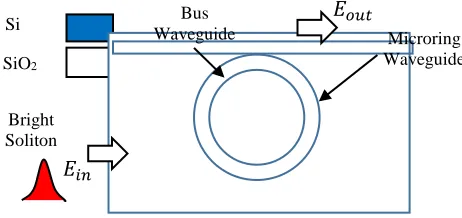
The all-pass configuration of microring resonator system comprises one bus waveguide which physically contact with side the microring waveguide. In this work the SOI microring system is used that consist of silicon as the core waveguide and silicon oxide as the cladding material [14, 15]. The microring resonator system is operated by applying the bright soliton pulse with 1.55m wavelength into the input port of the configuration as shown in Figure 1.
Figure 1 All-pass microring resonator system with the bright
soliton pulse as the input source
The propagation of the optical fields is discussed based on mathematical formulation based on the transfer matrix method [16] the consideration of nonlinear material properties as the resonator medium for the all-pass configuration [17]. The analytical derivation of the optical transfer functions and optical transmission equations are performed to simulate the propagation of soliton pulse inside all-pass microring resonator. The bright soliton equation are used as the input pulse 𝐸𝑖𝑛 which has been applied through the input port of microring resonator system as [18, 19]
𝐸𝑖𝑛= 𝐴 𝑠𝑒𝑐ℎ [
𝑇
𝑇𝑜
] 𝑒𝑥𝑝 [( 𝑧
2𝐿𝐷
) − 𝑖𝜔𝑜𝑡] (1)
Here 𝐸𝑖𝑛 referred to the electric field of bright soliton pulses for input. 𝐴 is amplitude of the optical field and 𝑧 is the propagation distance and 𝑇 is the pulse
propagation time with respect to a moving frame 𝑡 − 𝛽1𝑧 as t is soliton phase shift time. 𝑇𝑜 is the pulse width which is related to soliton pulses dispersion length 𝐿𝐷=
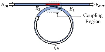
𝑇𝑜/|𝛽2|, where 𝛽1and 𝛽2are the coefficients of the linear and second-order terms of Taylor expansion of propagation constant and 𝑖𝜔𝑜𝑡 is the optical phase shift [20-22]. The phase shift of the soliton pulse is related to temporal coherent function of the input pulse which consist of the nonlinear Kerr effect. Several parameters are needed to be considered for the derivation which are electric field signal Ei, phase shift ξ, cross-coupling 𝑖𝑆𝑖 and self-coupling 𝐶𝑖parameters. The cross and the self-coupling have been illustrated as the black and red arrows within the coupling region as shown in Figure 2.
SiO2
Si
Bright Soliton
𝐸
𝑖𝑛𝐸
𝑜𝑢𝑡Bus
Waveguide Microring
Figure 2 Schematics diagram of all-pass microring resonator system
The all-pass configuration comprises of a coupling region in which will provide 2 by 2 coupled mode. The 2x2 coupler can be measured by multiply the optical propagation field with 𝑖𝑆1 and 𝐶1 coefficients which indicates the coupling of propagation field into other waveguide and transmit within same waveguide respectively. The coupling loss 𝛾1 and the coupling coefficient 𝜅1are fixed parameters needed to be considered in the coupling parameter as Equations (2) and (3)[14, 18, 23].
𝑖𝑆1= √(1 − 𝛾1)(𝜅1) (2)
𝐶1= √(1 − 𝛾1)(1 − 𝜅1) (3)
The soliton light pulse is fed into input port and propagated through the bus waveguide of the microring resonator system. During the propagation, a portion of input soliton pulse is coupled into the ring resonator due to the cross-coupling and rest of soliton pulse travelled along the bus waveguide to the output port [22]. The relation between circulating field 𝐸1, input soliton pulse 𝐸𝑖𝑛, phase shift ξ and output signal
𝐸𝑜𝑢𝑡can be expressed as Equations (4) by using transfer matrix analysis [24-26].
(𝐸1
𝐸𝑜𝑢𝑡) = (
𝐸𝑖𝑛
𝐸2) (
𝑖𝑆1 𝐶1
𝐶1 𝑖𝑆1) (4)
Inside the ring waveguide, the electric field of pulse is experienced single-pass phase shift ξ [7, 17, 27] as it propagated to complete a round trip which define as
𝜉 = exp (−𝛼𝐿
2 + 𝑖𝜃) (5)
Here L is the propagation length, α is the attenuation constant of power loss in ring per unit length. The single pass phase shift is included in the total phase shift of the system since the microring resonator systems are made by the SOI material nonlinear properties [24]. The phase shift can be described in complex form as
𝑖𝜃 = 𝑖𝑘𝑛𝐿 (6)
The nonlinearity phenomenon are considerred inside the system with the change of the total refractive index n due to change in optical intensity which
related to the power of circulating field as illustrates in Equations (7) and (8), where 𝑛𝐿is linear refractive index and 𝑛𝑁𝐿is nonlinear refractive index. This relationship between the optical power P and the refractive index n is called the Kerr effect as given in Equation (8) [22].
𝑛 = 𝑛𝐿+ 𝑛 𝑁𝐿𝐼1 (7)
𝑛 = 𝑛𝐿+ 𝑛 𝑁𝐿
𝑃1
𝐴𝑒𝑓𝑓 (8)
The optical circulating field 𝐸1 with respect to input field 𝐸𝑖𝑛can be obtained as Equation (9) by the derivation from Equation (4).
𝐸1=
𝑖𝑆1𝐸𝑖𝑛
1 − 𝐶1𝜉
(9)
The optical field of 𝐸2can be expressed as
𝐸2= 𝜉 (
𝑖𝑆1𝐸𝑖𝑛
1 − 𝐶1𝜉
) (10)
Thus, the output electric field and output power are obtained by substituting the Equations (9) and (10) into lower part of matrix equation Equation (4) which given as Equations (11) and (12) [28].
𝐸𝑜𝑢𝑡= 𝐸𝑖𝑛
𝐶1− 𝜉(1 − 𝛾)
1 − 𝐶1𝜉
(11)
𝑃𝑜𝑢𝑡= (𝐸𝑜𝑢𝑡)(𝐸𝑜𝑢𝑡∗) = |𝐸𝑜𝑢𝑡|2 (12)
The output-to-input power relation is obtained as Equation (11) and used to analyze the optical bistability effect of all-pass configuration of microring resonator system. The similar steps of derivation have been applied to the all-pass Mobius configuration which comprises of two radius (𝑅1 and 𝑅2 ) per roundtrip as compared to the previous configurations as shown in Figure 3.
The subscript m is introduced to designate the electric fields of all-pass Mobius configuration. The propagation equation also can be determined by using transfer matrix as
(𝐸1𝑚
𝐸𝑜𝑢𝑡𝑚
) = (𝐸𝑖𝑛
𝐸3𝑚
) (𝑖𝑆𝐶1 𝐶1
1 𝑖𝑆1) (13)
The circulating field inside the mobius ring waveguide exhibits the phase shift as follows
(𝐸2𝑚
𝐸3𝑚
) = (𝐸1𝑚
𝐸2𝑚
) (𝜉1 0
0 𝜉2) (14)
The total phase shift of the resonator system consists 2 type of phase shifts which are primary and secondary phase shift. The primary and secondary phase shift are represented the phase shift of the pulse as it propagated in the outer radius R1, and the inner
Figure 3 Schematic diagram of all-pass Mobius configuration
The optical field 𝐸3𝑚need to be considered into the propagation system since the electric field 𝐸2𝑚still experienced secondary phase shift 𝜉2before coupling to the bus waveguide. The total phase shift can be expressed as
𝜉𝑇= exp (
−𝛼𝐿𝑜𝑢𝑡+𝑖𝑛
2 + 𝑖𝜃𝑜𝑢𝑡+𝑖𝑛) (16)
With the inner and outer phase shift are given as
𝜉1= exp (
−𝛼𝐿𝑜𝑢𝑡
2 + 𝑖𝜃𝑜𝑢𝑡) (16)
𝜉2= exp (
−𝛼𝐿𝑖𝑛
2 + 𝑖𝜃𝑖𝑛)
(17)
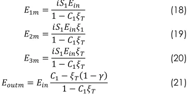
where the inner 𝐿𝑖𝑛= 2𝜋𝑅2and outer 𝐿𝑜𝑢𝑡= 2𝜋𝑅1 are the propagation length which obtained from radius 𝑅2 and radius 𝑅1 of the all-pass Mobius configuration as shown in Figure 3.After the derivation all optical fields within the system can be obtained in terms of input signal which given as
𝐸1𝑚=
𝑖𝑆1𝐸𝑖𝑛
1 − 𝐶1𝜉𝑇
(18)
𝐸2𝑚=
𝑖𝑆1𝐸𝑖𝑛𝜉1
1 − 𝐶1𝜉𝑇
(19)
𝐸3𝑚=
𝑖𝑆1𝐸𝑖𝑛𝜉𝑇
1 − 𝐶1𝜉𝑇
(20)
𝐸𝑜𝑢𝑡𝑚= 𝐸𝑖𝑛
𝐶1− 𝜉𝑇(1 − 𝛾)
1 − 𝐶1𝜉𝑇
(21)
Thus, the optical output power with respect to the input power of the system can be obtained as
𝑃𝑜𝑢𝑡𝑚= (𝐸𝑜𝑢𝑡𝑚)(𝐸𝑜𝑢𝑡𝑚∗) = |𝐸𝑜𝑢𝑡𝑚|2
= |𝐸𝑖𝑛
𝐶1− 𝜉𝑇(1 − 𝛾)
1 − 𝐶1𝜉𝑇
|
2 (22)
The optical output power in Equation (22) is derived to investigate the optical bistability properties of output-to-input power relation for all-pass Mobius configuration. The output power equation shows the effect of the self-coupling parameter, total phase shift and propagation loss towards optical bistability of the Mobius microring resonator system.
3.0 RESULTS AND DISCUSSION
In this section, the all-pass-type configurations of microring resonator are modelled based on the consideration of the practical ring resonator physical parameters such as refractive index, nonlinear index, radius, attenuation constant, coupling coefficient and effective area. The all-pass configuration comprise of a bus waveguide which attached to a single ring waveguide with lateral coupling[17].
The microring resonator is made by the SOI material which consist of a silicon Si medium and SiO2 silica as
the cladding with 2.5 effective refractive index [29] and 4.5×10⁻¹⁸ m2/W nonlinear refractive index[30]. The
microring resonator system is operated generally with 0.5 coupling coefficient κ and 0.01 propagation loss 𝛾
for obtaining the nonlinearity and optical bistability. The radius of all-pass microring resonator system is 2.5 μm and for all-pass mobius configuration comprises of two radius which are 1.5 μm for R2 and 2.5 μm R1. The
effective area of the system is 450nm × 220nm[31] with the attenuation constant of 0.02 dB/cm[32]. The MRR systems are simulation as refer to the optical soliton pulse propagation within the bus waveguide and coupling into ring waveguide as the pulse reached the ring waveguide. The iteration of MRR system is used to simulated circulating pulse in the ring and undergo the interferences between circulating and coupling pulse from the bus waveguide. The bright soliton laser pulse [33] is used as the input source with 50mW operating power, and 1.55 μm wavelength [34] as shown in Figure 4. The optical spectrum of the bright soliton pulse is simulated based on Equation (1) which comprises several fixed parameters as dispersion length 𝐿D, pulse width and propagation length. The red dashed line indicates the 50 mW peak power of the soliton pulse at 1.55 μm which has been fed in the microring resonator system.
Figure 4 Optical bright soliton signal spectrum
The generation of optical power transmission is discussed based on the iterative method which applied to the transfer matrix analysis of propagation equation. The iterative equation have been simulated to obtain optical circulating powers and optical output power.
1.51 1.52 1.53 1.54 1.55 1.56 1.57 1.58 1.59 x 10⁻⁶ 0
0.01 0.02 0.03 0.04 0.05
In
p
u
t P
ow
er
(
W)
Wavelength(m)
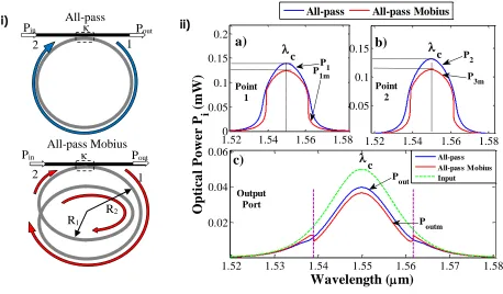
Figure 5 The optical power spectrum of all-pas and all-pass Mobius configuration i) schematics diagram with circulating points (1 and 2) of optical field , ii) (a) and (b) are the power of circulated field at point 1 and point 2 respectively, c) is the output power of the microring system
The circulating power of electric fields E1 and E2 of
the all-pass are compared with the power of electric field E1m and E3m of all-pass Mobius configuration
which defined as Equation (4) and (13). Figure 5 i) shows the position of circulating fields E1, E1m, and E2, E3m which labelled as 1 and 2 for both configuration
before and after coupling region respectively.
The legends of ‘all-pass’ and ‘all-pass M’ of the graph represent the power of all-pass and all-pass Mobius configuration respectively. In Figure 5 ii) a) and b), the peak powers of 1550 nm centre wavelength are obtained for both configuration. The all-pass configuration of microring resonator produces 13.93 mW peak power at point 1 and 13.09 mW at point 2 which are higher than Mobius configuration with 12.39 mW at point 1 and 11.21 mW at point 2. The all-pass Mobius configuration provides lower peak power at output port with 3.65mW as compared to the conventional all-pass configuration which generated 3.97mW peak power which illustrated in Figure 5 ii) c). The spectrum of all-pass mobius output power shows a small perturbation of the soliton shape due to the enhancement of nonlinear effect by the extra phase shift ξR2 which happened as the pulses propagated in
inner radius R2 of the resonator system as depicts in
Figure 5 ii) b). The extra phase shift triggers the nonlinear effect with respect to the based on the circulating power E2m before reach E3m at point 2. Thus,
the increasing of propagation roundtrip can affect the shape of the output soliton pulse which has
decrement at 1.539 μm and 1.561 μm wavelength as purple dashed line in Figure 5 c).
The slightly lower output power spectrum in the Mobius-type configuration is due to the losses which occurs as the soliton pulse travel in extra circulation trail of R2. The second circulation trail provides the
additional phase shift as exp
L/ 2iknl
to theincident pulse with the attenuation loss -α. The phase shift reduces the optical electric field power as the soliton pulse propagates from point 1 to point 2 in circulation trails in all-pass Mobius configuration as Figure 5 i). The power of the output signal is lower as compared to the circulated power at point 1 and 2. The decrement of the output power is caused by the coupling losses ‘γ’ which occurred as the pulse coupled back into the bus waveguide within the microring resonator system. The optical bistability can be obtained by inspecting the output to input relation of MRR system for both configuration as shown in Figure 6. The result of the relation shows that all-pass Mobius configuration able to produce the optical bistability behavior of output signal which is contrast with the conventional pass configuration. The all-pass configuration only provides the slightly nonlinear relation between output to input power. The all-pass Mobius configuration generates the optical bistability behavior of output-input signal in form of clockwise operation of hysteresis loop as illustrated with the green arrow in Figure 6). The brown dashed line shows the range of the input power that undergoes the
1
2
All-pass
P
inκ
P
outAll-pass Mobius
P
inκ
P
out1
2
i)
ii)
R
1R
21.52
1.53
1.54
1.55
1.56
1.57
1.58
0.02
0.04
0.06
Opti
ca
l
P
o
w
er
P
i
(m
W)
Wavelength (
m)
1.52
0
1.54
1.56
1.58
0.05
0.1
0.15
0.2
1.52
1.54
1.56
1.58
0.05
0.1
0.15
All-pass
All-pass Mobius
All-pass All-pass Mobius Input
a)
c
c
c)
c
P
out
Poutm
Point 1
b)
Point 2
P2
P
3m
P1mP1
optical bistable effects which initiated at 15.79 mW and end at 18.10mW. The mean of the minimum input power and maximum input power can be introduced as threshold power Pthof the switching purposes [35].
The threshold power triggered on and off operation powers which obtained by the minimum and maximum output powers signal. The hysteresis loop comprises 16.95 mW P_th with 9.11 mW off operation power and 12.78 mW on operation power. The difference between the on and off operation is known as switching power in which obtained as 3.67mW for the all-pass mobius configuration. The optical bistability behaviour of the output-input power relation is operated by varying the input power signal. The all-pass mobius configuration operated a clockwise hysteresis loop of optical bistability as shown in Figure 6.
Figure 6 Hysteresis loop of optical bistability behaviour on all-pass and all-all-pass mobius configuration MRR system
The increasing in input power produced the increasing in output power until the amount of the input power exceeding the threshold point, then the switching operation will be triggered. For clockwise hysteresis loop, the switch off operation will occur when the input power is increased beyond the threshold power which in contrast with the on operation that needed the decrement of input power below threshold power.
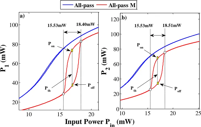
In Figure 7, the optical bistability can be observed clearly in the all-pass mobius configuration which contrast with the conventional all-pass configuration the output-input relation shows on a small change of circulated power along the variation of the input power. The small change is not suitable to be used for the switching purposes. At point 1, the input optical power is initiated to undergo bistable effect at 15.53 mW and end at 18.40mW which is lower range of optical bistability than power at point 2. The optical threshold powers are obtained as 16.97mW for point 1 and 17.02 mW at point 2 as shown as the dashed line between two yellowish rectangular dotted in Figures 7 a) and b) respectively. The on operation powers for point 1 and 2 circulated field are attained as 74.40 mW and 67.86 mW respectively and the off operation powers are obtained as 37.43 mW and 34.24mW respectively. Thus, the switching power of point 1 and 2 can be calculated as 36.97 mW and 33.62 mW respectively.
Figure 7 Circulated power at point 1 a) and 2 b) plotted with respect to input power
10 15 20 25
6 8 10 12 14 16 18
Thro
ug
h
P
o
w
er
P
ou
t
(m
W)
Input Power P
in
(mW)
All-pass All-pass-M
18.10mW
P on 15.79mW
Threshold Input Power P
th P
off
10
15
20
20
40
60
80
100
P
1
(m
W)
Input Power P
in
(mW)
All-pass
All-pass M
10
15
20
25
0
20
40
60
80
100
120
P
2
(m
W)
b)
a)
18.40mW 15.53mW 18.51mW
15.53mW
P
th
P
th
P
on
Poff
Pon
The relation between intracavity power of P1 and P2
with the input power are obtained the anti-clockwise bistability hysteresis loops. As the input power increase, the optical output power triggered the on
operation as the optical power increased exponentially. As the input power increase up to the end the hysteresis shape the signal has another possible output which known as off operation of the optical flip-flop. The on switching operation can be performed by increasing the input power beyond the threshold power as shown Figure 7. Practically, the increasing of the optical power will led to the electron recombination within the core material and enhance the refractive index of the material. The rise of the refractive index are increased the wavenumber and phase of the input signal and moved the Bragg resonance and photonics band to a broaden wavelength. Since the Bragg resonance wavelength becomes nearer to the input wavelength, the internal optical power is increased and induced the positive feedback of the hysteresis loop which triggered the upward switching of bistability. Thus, the positive feedback shows the increase of the nonlinear refractive index, internal optical power and the Bragg resonance which amplified the resonance signal of the system. The output signal is remained at high value Pon even the
input signal is decreased to the initial state as threshold point Pth which illustrate in Figures 7 a) and
b). The larger output signal can be obtained by new position of Bragg-resonance which increase the resonance signal. The constant decrement of carrier-density is needed to hold the position of Bragg resonance and sustain high value optical output power[35]. The off operation occurs when the input power has been decreased lower than threshold power and enhances the carrier density to recover which reduce the waveguide refractive index. The Bragg resonance wavelength is reduced approaching the value of centre wavelength by the SPM within the system. As the resonance peak higher the signal wavelength, the positive feedback loop produces shorter Bragg resonance wavelength and decrease the output power[35]. Thus, the off operation of optical switching is possible to be conducted by the anticlockwise hysteresis loop of the all-pass Mobius configuration.
4.0 CONCLUSION
The analytical formulation is performed for the propagation electric field with the microring resonator system based on transfer matrix method. The all-pass Mobius able to produce great phase shift as compare to conventional all-pass configuration of microring resonator system. The comparison between Mobius and conventional microring resonator system is demonstrated based on all-pass configuration for the transmission output power and the optical bistability on output-to-input relation. The all-pass Mobius configuration able to exceed the
performance of convectional configuration in which able to obtain the nonlinear transmission output power spectrum and produce clockwise switching operation of bistable hysteresis loop. The result shows that the all-pass Mobius provides low transmission peak power of 3.65 mW as compared to the conventional all-pass configuration with distorted bell shape spectrum. The output-to-input relation of both design shows that the Mobius configuration is able to produce a higher hysteresis loop width of the bistable signal from 15.79mW to 18.10mW input power. The switching power of the optical bistability in Mobius configuration is 3.67 mW for threshold power of 16.95mW. This work demonstrates the Mobius configuration is more applicable to be used for all-optical switching applications as compared to the conventional configuration.
Acknowledgement
We would like to thank the Laser Centre, Ibnu Sina ISIR, Universiti Teknologi Malaysia (UTM) and King Mongkut’s Institute of Technology (KMITL), Thailand for providing research facilities. This research work has supported by UTM’s Flagship (00G39) research Grant and MyBrain15 scholarship.
References
[1] Lynch, S. and A. Steele. 2011. Nonlinear Optical Fibre Resonators with Applications in Electrical Engineering and Computing. In Applications of Chaos and Nonlinear Dynamics in Engineering-Vol. 1. 2011, Springer-Verlag Berlin: London.
[2] Yanik, M. F., S. H. Fan, M. Soljacic, and J. D. Joannopoulos. 2003. All-optical Transistor Action with Bistable Switching in a Photonic Crystal Cross-Waveguide Geometry. Optics Letters. 28(24): 2506-2508.
[3] Yang, W. G., A. Joshi, and M. Xiao. 2007. Single-photon all-Optical Switching Using Coupled Microring Resonators. Pramana-Journal of Physics. 69(2): 219-228.
[4] Han, X. F., Y. X. Weng, R. Wang, X. H. Chen, K. H. Luo, L. A. Wu, and J. M. Zhao. 2008. Single-photon Level Ultrafast All-Optical Switching.Applied Physics Letters. 92(15).
[5] Bahrampour, A. R., M. Karimi, M. A. Qamsari, H. R. Neiad, and S. Keyvaninia. 2008. All-optical Set-reset Flip-flop Based on the Passive Microring-Resonator Bistability. Optics Communications. 281(20): 5104-5113.
[6] Felber, F. and J. Marburger. 1976. Theory of Nonresonant Multistable Optical Devices. Applied Physics Letters. 28(12): 731-733.
[7] Alexandropoulos, D., H. Simos, M. J. Adams, and D. Syvridis. 2008. Optical Bistability in Active Semiconductor Microring Structures. IEEE Journal of Selected Topics in Quantum Electronics. 14(3): 918-926.
[8] Shafiei, M. and M. Khanzadeh. 2010. Low-threshold Bistability in Nonlinear Microring Tower Resonator.Optics Express. 18(25): 25509-25518.
[9] Zhang, L. B., Y. H. Fei, Y. M. Cao, and S. W. Chen. 2014. Experimental Observations of Thermo-optical Bistability and Self-pulsation in Silicon Microring Resonators.Journal of the Optical Society of America B-Optical Physics. 31(2): 201-206.
Transmission. Optical Fiber Communication Conference. Th2A. 27.
[11] Bahadoran, M., J. Ali, and P.P. Yupapin. 2013.Ultrafast all-Optical Switching Using Signal Flow Graph for PANDA Resonator.Applied Optics. 52(12): 2866-2873.
[12] Pond, J. M., S. J. Liu, and N. Newman. 2001. Bandpass Filters Using Dual-Mode and Quad-Mode Mobius Resonators.Ieee Transactions on Microwave Theory and Techniques. 49(12): 2363-2368.
[13] Li, S., L. Ma, V. Fomin, S. Böttner, M. Jorgensen, and O. Schmidt. 2013. Non-integer Optical Modes in a M\" Obius-Ring Resonator.arXiv preprint arXiv:1311.7158.
[14] Bahadoran, M., A. F. A. Noorden, K. Chaudhary, M. S. Aziz, J. Ali, and P. Yupapin. 2014. Nano Force Sensing Using Symmetric Double Stage Micro Resonator.Measurement. 58: 215-220.
[15] Long, Y., H. Zhang, C. Li, C. Gui, Q. Yang, and J. Wang. 2015. Ultra-high Peak Rejection Notch Microwave Photonic Filter Using a Single Silicon Microring Resonator. Optical Fiber Communication Conference. W2A. 58. [16] Poon, J. K. S., J. Scheuer, S. Mookherjea, G. T. Paloczi, Y. Y.
Huang, and A. Yariv. 2004. Matrix Analysis of Microring Coupled-resonator Optical Waveguides. Optics Express. 12(1): 90-103.
[17] Heebner, J., R. Grover, and T. A. Ibrahim. 2008. Optical Microresonators: Theory, Fabrication, and Applications. London: Springer Verlag.
[18] Bahadoran, M., A. F. A. Noorden, K. Chaudhary, F. S. Mohajer, M. S. Aziz, S. Hashim, J. Ali, and P. Yupapin. 2014. Modeling and Analysis of a Microresonating Biosensor for Detection of Salmonella Bacteria in Human Blood.Sensors. 14(7): 12885-12899.
[19] Rajan, M. S. M., A. Mahalingam, and A. Uthayakumar. 2014. Nonlinear Tunneling of Optical Soliton in 3 Coupled NLS Equation with Symbolic Computation. Annals of Physics. 346: 1-13.
[20] Agrawal, G. P. 2011. Nonlinear Fiber Optics: Its History and Recent Progress [Invited].Journal of the Optical Society of America B-Optical Physics. 28(12): A1-A10.
[21] Kivshar, Y. S. and G. Agrawal. 2003. Optical Solitons: From Fibers to Photonic Crystals: Academic Press.
[22] Lynch, S. 2004. Dynamical Systems with Applications using MATLAB®). Boston: Springer.
[23] Bahadoran, M., M. S. Aziz, A. F. A. Noorden, M. A. Jalil, J. Ali, and P .P. Yupapin. 2014. Novel Approach to Determine the Young's Modulus in Silicon-on-Insulator Waveguide Using Microring Resonator.Digest Journal of Nanomaterials and Biostructures. 9(3): 1095-1104.
[24] Rukhlenko, I. D., M. Premaratne, and G. P. Agrawal. 2010. Analytical Study of Optical Bistability in Silicon Ring Resonators.Optics Letters. 35(1): 55-57.
[25] Nikolova, D. and K. Bergman. 2014. Analysis of Silicon Photonic Microring-based Multistage Switches. Integrated Photonics Research, Silicon and Nanophotonics. JT2B. 3. [26] Lakra, S. and S. Mandal. 2014. Modeling and Performance
Analysis of Vertically Coupled Triple Microring Resonator in The Z Domain.Applied optics. 53(36): 8381-8388.
[27] Bahadoran, M., A. F. A. Noorden, F. S. Mohajer, M. H. Abd Mubin, K. Chaudhary, M. A. Jalil, J. Ali, and P. Yupapin. 2014. Detection of Salmonella Bacterium in Drinking Water Using Microring Resonator.Artificial Cells, Nanomedicine, and Biotechnology. (0): 1-7.
[28] Banerjee, S., M. Mitra, and L. Rondoni. 2011. Applications of Chaos and Nonlinear Dynamics in Engineering. Springer.
[29] Nawrocka, M. S., T. Liu, X. Wang, and R. R. Panepucci. 2006. Tunable Silicon Microring Resonator with Wide Free Spectral Range.Applied Physics Letters. 89(7).
[30] Koos, C., L. Jacome, C. Poulton, J. Leuthold, and W. Freude. 2007. Nonlinear Silicon-On-Insulator Waveguides for All-Optical Signal Processing. Optics Express. 15(10): 5976-5990.
[31] Shuai, L., W. Yuanda, Y. Xiaojie, A. Junming, L. Jianguang, W. Hongjie, and H. Xiongwei. 2011. Tunable Filters Based on an SOI Nano-Wire Waveguide Micro Ring Resonator. Journal of Semiconductors. 32(8): 084007.
[32] Herrera, G. V., T. Bauer, M. G. Blain, P. E. Dodd, R. Dondero, E. J. Garcia, P. C. Galambos, D. L. Hetherington, J. J. Hudgens, F. B. McCormick, G. N. Nielson, C. D. Nordquist, M. Okandan, R. H. Olsson, K. Ortiz, M. R. Platzbecker, P. J. Resnick, R. J. Shul, M. J. Shaw, C. T. Sullivan, and M. R. Watts. 2008. SOI-Enabled MEMS Processes Lead to Novel Mechanical, Optical, and Atomic Physics Devices. 2008 IEEE International SOI Conference, Proceedings. 5-8.
[33] Sanchez, F., P. Grelu, H. Leblond, A. Komarov, K. Komarov, M. Salhi, A. Niang, F. Amrani, C. Lecaplain, and S. Chouli. 2014. Manipulating Dissipative Soliton Ensembles in Passively Mode-Locked Fiber Lasers. Optical Fiber Technology. 20(6): 562-574.
[34] Oktem, B., C. Ulgudur, and F. O. Ilday. 2010. Soliton-Similariton Fibre Laser.Nature Photonics. 4(5): 307-311. [35] Maywar, D. N., G. P. Agrawal, and Y. Nakano. 2001.