ISSN: 2319-8753
International Journal of Innovative Research in Science,
Engineering and Technology
(An ISO 3297: 2007 Certified Organization) Vol. 3, Issue 4, April 2014
Generation Fuel Cost Minimization of Power
Grid Using Primal Dual Interior Point OPF
(Optimal Power Flow) Method
1
Abdullah Umar, 2Anwar.S.Siddiqui, 3Naqui Anwer,
Research Scholar (EE), F/O Engineering, OPJS University, Churu, Raj., India.
Professor (EE), F/O Engineering & Technology, Jamia Millia Islamia, India.
Research Scholar (EE), F/O Engineering & Technology, Jamia Millia Islamia, India
Abstract: This paper presents an efficient and reliable interior point approach to obtain optimal power flow (OPF) problem solution. The Interior Point method (IP) is found to be the most efficient algorithm for optimal power flow solution. The IP algorithm is coded in MATLAB and the performance is tested on IEEE 14 bus test system with fuel cost minimization as objective function. It maintains good accuracy while achieving the high speed of convergence when compared to other known linear programming methods. The solution obtained by this algorithm proves to be robust to solve the OPF problem of power grid.
Keywords: Interior point method, optimal power flow, optimization techniques, cost minimization, power grid, MATLAB.
I. INTRODUCTION
Present day commercial OPF programs can solve very large and complex power systems optimization problems in a relatively less time. Many different solution methods have been suggested to solve OPF problems. In a conventional power flow, the values of the control variables are predetermined. In an OPF, the values of some or all of the control variables need to be known so as to optimize (minimize or maximize) a predefined objective. The OPF calculation has many applications in power systems, real-time control, operational planning, long-term planning and energy management systems (EMSs) [1–2]. OPF continues to be significant due to the growth in power system size and complex interconnections [3 – 4]. For example, OPF should support deregulation transactions or furnish information on what reinforcement is required. OPF studies can decide the tradeoffs between reinforcements and control options as per the results obtained from carrying out OPF studies. It is clarified when a control option enhances utilization of an existing asset (e.g., generation or transmission), or when a control option is an inexpensive alternative to installing new facilities. Issues of priority of transmission access and VAr pricing or auxiliary costing to afford price and purchases can be done by OPF.
The main goal of a generic OPF is to reduce the costs of meeting the load demand for a power system while up keeping the security of the system. From the viewpoint of an OPF, the maintenance of system security requires keeping each device in the power system within its desired operation range at steady-state. This will include maximum and minimum outputs for generators, maximum MVA flows on transmission lines and transformers, as well as keeping system bus voltages within specified ranges.
ISSN: 2319-8753
International Journal of Innovative Research in Science,
Engineering and Technology
(An ISO 3297: 2007 Certified Organization) Vol. 3, Issue 4, April 2014
angles as well. The OPF also is able to monitor system security issues including line overloads and low or high voltage problems. If any security problems occur, the OPF will modify its controls to fix them, i.e., remove a transmission line overload [13].
The quality of the solution depends on the accuracy of the model used. It is essential to define problem properly with clearly stated objectives be given at the onset. No two-power system utilities have the same type of devices and operating requirements. The model form presented here allows OPF development to easily customize its solution to different cases under study [5–8].
OPF, to a large extent depends on static optimization method for minimizing a scalar optimization function (e.g., cost). It was first introduced in the 1960s by Tinney and Dommel [3]. It employs first-order gradient algorithm for minimization objective function subject to equality and inequality constraints. Solution methods were not popular as they are computationally intensive than traditional power flow. The next generation OPF has been complex as power systems operation or planning need to know the limit, the cost of power, incentive for adding units, and building transmission systems a particular load entity.
II. OPTIMAL POWER FLOW CHALLENGES
The demand for an OPF tool has been increasing to assess the state and recommended control actions both for off line and online studies, since the first OPF paper was presented in 60’s. The thrust for OPF to solve problems of today’s deregulated industry and the unsolved problem in the vertically integrated industry has posed further challenges to OPF to evaluate the capabilities of existing OPF in terms of its potential and abilities [9].
Many challenges are before OPF remain to be answered. They can be listed as given below.
1. Because of the consideration of large number of variety of constraints and due to non linearity of mathematical models OPF poses a big challenge for the mathematicians as well as for engineers in obtaining optimum solutions. 2. The deregulated electricity market seeks answer from OPF, to address a variety of different types of market participants, data model requirements and real time processing and selection of appropriate costing for each unbundled service evaluation.
3. To cope up with response time requirements, modelling of externalities (loop flow, environmental and simultaneous transfers), practicality and sensitivity for on line use.
4. How well the future OPF provide local or global control measures to support the impact of critical contingencies, which threaten system voltage and angle stability simulated.
5. Future OPF has to address the gamut of operation and planning environment in providing new generation facilities, unbundled transmission services and other resources allocations.
Finally it has to be simple to use and portable and fast enough.
III. OPTIMAL POWER FLOW PROBLEM
In an OPF, the values of some or all of the control variables need to be found so as to optimise (minimise or maximize) a predefined objective. It is also important that the proper problem definition with clearly stated objectives be given at the onset. The quality of the solution depends on the accuracy of the model studied. Objectives must be modelled and its practicality with possible solutions.
Objective function takes various forms such as fuel cost, transmission losses and reactive source allocation. Usually the objective function of interest is the minimisation of total production cost of scheduled generating units. This is most used as it reflects current economic dispatch practice and importantly cost related aspect is always ranked high among operational requirements in power systems [15].
OPF aims to optimise a certain objective, subject to the network power flow equations and system and equipment operating limits. The optimal condition is attained by adjusting the available controls to minimise an objective function subject to specified operating and security requirements.
ISSN: 2319-8753
International Journal of Innovative Research in Science,
Engineering and Technology
(An ISO 3297: 2007 Certified Organization) Vol. 3, Issue 4, April 2014
Active power objectives
1. Economic dispatch (minimum cost, losses, MW generation or transmission losses) 2. Environmental dispatch
3. Maximum power transfer
Reactive power objectives
MW and MVAr loss minimization General goals
1. Minimum deviation from a target schedule 2. Minimum control shifts to alleviate Violations 3. Least absolute shift approximation of control shift
Among the above the following objectives are most commonly used:
(a) Fuel or active power cost optimisation (b) Active power loss minimisation
(c) VAr planning to minimise the cost of reactive power support
The mathematical description of the OPF problem is presented below:
OPF Objective Function for Fuel Cost Minimization
The OPF problem can be formulated as an optimization problem [10] and is as follows:
Total Generation cost function is expressed as:
( ) = ∑ ( + + ) (1)
The objective function is expressed as:
Min ( ) = ( , ) (2)
Subject to satisfaction of Non linear Equality constraints:
( , ) = 0 (3)
and Non Linear Inequality constraints:
ℎ( , )≤0 (4)
≤ ≤ (5)
≤ ≤ (6)
( ) is total cost function ( , ) is the scalar objective, ( , ) = 0 represents nonlinear equality constraints (power flow equations), andℎ( , ) is the nonlinear inequality constraint of vector arguments x, u.
ISSN: 2319-8753
International Journal of Innovative Research in Science,
Engineering and Technology
(An ISO 3297: 2007 Certified Organization) Vol. 3, Issue 4, April 2014
Bus voltage magnitudes and phase angles
MVAr output of generators designated for bus voltage control
Fixed parameters such as the reference bus angle
Non controlled generator MW and MVAr outputs
Non controlled MW and MVAr loads
Fixed bus voltages, line parameters
The vector u consists of control variables including:
Real and reactive power generation
Phase – shifter angles
Net interchange
Load MW and MVAr (load shedding)
DC transmission line flows
Control voltage settings
LTC transformer tap settings
The equality and inequality constraints are:
Limits on all control variables
Power flow equations
Generation / load balance
Branch flow limits (MW, MVAr, MVA)
Bus voltage limits
Active / reactive reserve limits
Generator MVAr limits
Corridor (transmission interface) limits
Constraints for Objective Function of Fuel Cost Minimization
The network equality constraints are represented by the load flow equations
( , )− + = 0 (7)
( , )− + = 0 (8)
Where:
( , ) = | |∑ | ‖ |cos ( − − ) (9)
( , ) = | |∑ | ‖ |sin ( − − ) (10)
= | |∟ (11) and load balance equation:
∑ ( )− ∑ ( )− = 0 (12)
The Inequality constraints representing the limits on all variables, line flow constraints are as:
≤ ≤ , i=1, 2,..., N (13) ≤ ≤ , i=1, 2,...,NG (14)
ISSN: 2319-8753
International Journal of Innovative Research in Science,
Engineering and Technology
(An ISO 3297: 2007 Certified Organization) Vol. 3, Issue 4, April 2014
− ≤ − ≤ , i=1,2,..., (16) Where i, j are the nodes of line − ≤ − ≤ , i=1,2,..., (17) Where i, j are the nodes of line
≤ i=1,2,..., (18) ≤ ≤ i=1,2,..., (19) ≤ ≤ i=1,2,..., (20)
IV. INTERIOR POINT METHOD
It has been found that, the projective scaling algorithm for linear programming proposed by N. Karmarkar is characterized by significant speed advantages for large problems reported to be as much as 12:1 when compared to the simplex method. Further, this method has a polynomial bound on worst-case running time that is better than the ellipsoid algorithms. Karmarkar’s algorithm is significantly different from Dantzig’s simplex method. Karmarkar’s interior point rarely visits too many extreme points before an optimal point is found. In addition, the IP method stays in the interior of the polytope and tries to position a current solution as the “center of the universe” in finding a better direction for the next move. By properly choosing the step lengths, an optimal solution is achieved after a number of iterations. Although this IP approach requires more computational time in finding a moving direction than the traditional simplex method, better moving direction is achieved resulting in less iteration. In this way, the IP approach has become a major rival of the simplex method and has attracted attention in the optimization community. The Interior Point Method [10] is one of the most efficient algorithms. The IP method classification is a relatively new optimization approach that was applied to solve power system optimization problems in the late 1980s and early 1990s and as can be seen from the list of references [11]. The Interior Point Method (IPM) can solve a large scale linear programming problem by moving through the interior, rather than the boundary as in the simplex method, of the feasible reason to find an optimal solution. The IP method was originally proposed to solve linear programming problems; however later it was implemented to efficiently handle quadratic programming problems. It is known as an interior method, since it finds improved search directions strictly in the interior of the feasible space as shown in Fig.1.
Fig.1. Polytope of a two – dimension feasible region.
The basic ideas involved in the iteration process of Interior Point Method as proposed by N. K.Karmarkar [12], are given below. In order to have a comprehensive idea of the optimisation process, the difference between the simplex and interior point methods is described geometrically. Consider an interior path, described by xi, as shown in Fig.1. In the simplex method the solution goes from corner point to corner point, as indicated by xi. The steepest descent direction is represented by c. The main features of the IPM as shown in Fig.1 are:
1) Starting from an interior point, the method constructs a path that reaches the optimal solution after little iteration (less than the simplex method).
2) The IPM leads to a “good assessment” of the optimal solution after the first few iterations. This feature is very important, because for each linearization of the original formulation an exact result of Quadratic Programming problem is not imperative. Normally it is enough to obtain a point near the optimal solution because each QP sub problem is already an approximation of the original problem.
ISSN: 2319-8753
International Journal of Innovative Research in Science,
Engineering and Technology
(An ISO 3297: 2007 Certified Organization) Vol. 3, Issue 4, April 2014
been found. The formal is the determination of a search direction for each variable in the search space by a Newton’s method. The lateral is the determination of a step length normally assigned a value as close to unity as possible to accelerate solution convergence while strictly maintaining primal and dual feasibility. A calculated solution in each iteration to be checked for optimality by the Karush – Kuhn – Tucker (KKT) conditions, which consist of primal feasibility, dual feasibility and complementary slackness.
OPF Problem Formulation by Primal — Dual Interior Point Method
As has been mentioned, the objective function considered in this paper is to minimize the total production cost of scheduled generating units. OPF formulation consists of three main components: objective function, equality constraints, and inequality constraints [16-17].
An OPF problem is generally formulated as per Eq. (1) – (6).
Objective Function
The objective function is given by Eq. (2) and is reproduced below.
( ) = ∑ ( + + )
Equality Constraints
The equality constraints are active/reactive power flow equations.
Nonlinear equations can be linearized by the Taylor’s expansion using
∆ ( , )
∆ ( , ) =
∆ ∆
Where is the Jacobian matrix.
Transmission loss (PL) can be directly calculated from the power flow.
Inequality Constraints
The inequality constraints consist of generator active/reactive power limits, voltage magnitude limits, and transformer tap position limits.
Solution Algorithm
The PDIPM method is started by arranging a primal quadratic programming problem into a standard form as:
Minimize + (21)
Subject to = , ≥0 (22)
Eq. (21) can be transformed into the corresponding dual problem having the form.
ISSN: 2319-8753
International Journal of Innovative Research in Science,
Engineering and Technology
(An ISO 3297: 2007 Certified Organization) Vol. 3, Issue 4, April 2014
− + (23)
Subject to – + + = ,
≥0 (24)
= , ≥0 (Primal feasibility) (25)
– + + = , ≥0 (Dual feasibility) (26)
= (Complementary Slackness) (27)
Where
=( ) (28)
From the KKT conditions Eq. (25-27), the directions of translation are calculated using the Newton’s method which yields the following system Eq.
0 0
− 0
=
−
− + + −
−
(29)
The right hand side of Eq. (29) is so-called slackness vectors and can be assigned to new variables as
= − (30)
= + − − (31)
= − (32)
From Eq. (29) – (32), we have
= (33)
− + + = (34)
+ = (35)
Combining and rearranging Eq. (34) and Eq. (35) gives
− + ( + ) = ( + ) ( − ) (36)
With Eq. (33) and Eq. (36), a dual search direction can be derived a
ISSN: 2319-8753
International Journal of Innovative Research in Science,
Engineering and Technology
(An ISO 3297: 2007 Certified Organization) Vol. 3, Issue 4, April 2014
The equation for a primal search direction can be derived from Eq. (36).
= ( + ) [ ( − ) + ] (38)
With the primal search direction and Eq. (35), a slack search direction can be obtained by
= ( − ) (39)
To find appropriate step lengths while keeping the primal and dual problem feasible, Eq. (40) – Eq. (43) are used.
= min − | < 0 (40)
= min − | < 0 (41)
= min( , ) (42)
= 0.99 (43)
An updated solution can be computed by Eq. (44) – (46).
= + (44)
= + (45)
= + (46)
Algorithm for PDIPM
The PDIPM algorithm applied to the OPF problem is summarized step-by-step as follows.
Step 1: Read relevant input data.
Step 2: Perform a base case power flow by a power flow subroutine.
Step 3: Establish an OPF model.
Step 4: Compute Eq. (30) – (32).
Step 5: Calculate search directions with Eq. (37) – (39).
Step 6: Compute primal, dual and actual step-lengths with Eq. (40) – (43).
Step 7: Update the solution vectors with Eq. (44) – (46).
Step 8: Check if the optimality conditions are satisfied by Eq. (25) – (27) and if μ ≤ ε (ε =0.001 is chosen). If yes, go to the next step. Otherwise go to step 4.
Step 9: Perform the power flow subroutine.
Step 10: Check if there are any violations in Eq. (15) and Eq. (19). If no, go to the next step; otherwise, go to step 4.
Step 11: Check if a change in the objective function is less than or equal to the prespecified tolerance. If yes, go to the next step; otherwise, go to step 4.
ISSN: 2319-8753
International Journal of Innovative Research in Science,
Engineering and Technology
(An ISO 3297: 2007 Certified Organization) Vol. 3, Issue 4, April 2014
V. OPF TEST CASE: - IEEE 14 BUS TEST SYSTEM
In this study, the standard IEEE 14-Bus 5 Generator test system is considered to investigate effectiveness of the proposed method. The IEEE 14-bus system has 20 transmission lines [14]. The single line diagram is shown in Fig.2.
Fig. 2. IEEE 14-Bus test System
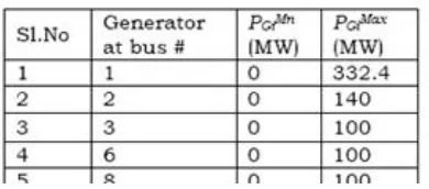
The values of fuel cost coefficients are given in Table 1. The total load demand of the system is 259 MW and 5 -Generators should share load optimally.
Table 1: Generator Fuel Cost Coefficients
Table 2: Generator Operating Limits
(Minimum or Maximum Generation limits of Generators are presented in Table 2)
ISSN: 2319-8753
International Journal of Innovative Research in Science,
Engineering and Technology
(An ISO 3297: 2007 Certified Organization) Vol. 3, Issue 4, April 2014
VI. OPF RESULTS
CPU Computational Time= 0.29 seconds Total Generation Cost = 8081.53 $/hr
Table 3.1 OPF Solution: Generation Schedule
Parameter OPF Solution by IP Method (MW)
PG1 194.33
PG2 36.72
PG3 28.74
PG6 11.20
PG8 8.50
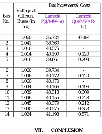
Table 3.2 Voltage Magnitude and Incremental Costs at Different Buses.
Bus No.
Voltage at different Buses (in p.u)
Bus Incremental Costs
Lambda P($/MW-hr)
Lambda
Q($/MVAR-hr)
1 1.060 36.724 -0.094
2 1.041 38.360 -
3 1.016 40.575 -
4 1.014 40.190 0.120
5 1.016 39.661 0.208
6 1.060 39.734 -
7 1.046 40.172 0.120
8 1.060 40.170 -
9 1.044 40.166 0.196
10 1.039 40.318 0.309 11 1.046 40.155 0.228 12 1.045 40.379 0.212 13 1.040 40.575 0.353 14 1.024 41.198 0.571
VII. CONCLUSION
ISSN: 2319-8753
International Journal of Innovative Research in Science,
Engineering and Technology
(An ISO 3297: 2007 Certified Organization) Vol. 3, Issue 4, April 2014
REFERENCES
[1] Carpentier, J. “Contribution to the economic dispatch problem”, Bull.Sac. France Elect, Vol.8, pp. 431-437, 1962.
[2] Carpinelli, G., Lauria, D. and Varilone, P. “Voltage stability analysis in unbalanced power systems by optimal power flow”, IEE Proceedings of Generation, Transmission and Distribution., Vol. 153, No. 3, pp.261-268, 2006.
[3] Dommel, H.W and Tinney, W.F. “Optimal power flow solutions,” IEEE Transactions on Power Apparatus and Systems, Vol. 87, No. 10, pp. 1866-1876, 1968.
[4] Devaraj, D. and Preetha Roselyn, J. “Genetic algorithm based reactive power dispatch for voltage stability improvement, International Journal of Electric power and energy systems, Volume 32, issue 10, pp.1151-1158, 2010.
[5] Esaka, T., Kataoka, Y., Ohtaka, T. and Iwamoto, S. “Voltage stability preventive and emergency preventive control using VIPI sensitivities”, Proc. of IEEE/PES Power Systems Conference and Exposition, Vol. 1, pp. 509-516, 2004.
[6] Florin Capitanescu and Louis Wehenkel. “A new iterative approach to the corrective security constrained optimal power flow problem”, IEEE Transactions on Power Systems, Vol. 23, No. 4, pp. 1533-154, 2008.
[7] Florin Capitanescu and Van Cutsem, T. “Preventive control of voltage security margins: A multicontingency sensitivity based approach”, IEEE Trans. on Power Systems, Vol. 17, No. 2, pp. 358-364, 2002.
[8] Florin Capitanescu, Van Cutsen, T. and Loiyis Wehenkel, “Coupling optimization and dynamic simulation for preventive, corrective control of voltage instability” IEEE Transactions on power systems, Vol. 24, No.2, pp.796-805, 2009.
[9] Ejbee, G.C and Wollenberg B.F,”Automatic contingency selecetion,” IEEE Transactions on power apparatus and systems, Vol.98, No.3, pp.97-108, 1989.
[10] Angel, L.Trigo, Jose, L.Martinez, Jesus Riqueline and Esther Romero. “A heuristic technique to determine corrective actions for reactive power flows”, Electric Power System Research, Vol. 81, issue 1, pp.90-98, 2011.
[11] Wang, X., Ejebe, G.C., Tong, J. and Waight, J.G. “Preventive / corrective control for voltage stability using direct interior point method”, IEEE Transactions on power systems, Vol.13, No.3, pp.878- 883, 1998.
[12] Bertram, T.J., Demaree, K.D. and Dangelmaier, L.C. “An Integrated Package for Real-Time Security Enhancement”, PICA Proc., Seattle, WA, pp.18-25, 1989.
[13] Amar nath, R V., Department of EEE, JNTU. URL-http://hdl.handle.net/10603/4566.
[14] Naqui Anwer, Anwar S. Siddiqui, Abdullah Umar, “Analysis of UPFC, SSSC with and without POD in Congestion Management of Transmission System”, 5th IEEE International Conference on Power Electronics, Delhi Technological University, New Delhi, December 06-08, 2012.
[15] Anwar S. Siddiqui, Naqui Anwer, Abdullah Umar, “Reducing Parametric Limitations of Transmission Lines Using Series FACTS Controllers”, IEEE sponsored National Conference, Galgotias College of Engineering & Technology, Greater Noida, India, 2014.
[16] Naqui Anwer, Anwar S. Siddiqui, Ahmad S. Anees, “A Lossless Switching Technique for Smart Grid Applications”, Elsevier International Journal of Electrical Power and Energy Systems, Vol. 49, pp 213-220, 2013.