Performance Analysis of PID and IMC
Controller for Hydrometallurgical Process
G.Guna1, P.Sivakumar2, Dr.D.Prabhakaran3, Dr.M.Thirumarimurugan4
P.G. Student, Department of Chemical Engineering, Coimbatore Institute of Technology, Coimbatore,
Tamil Nadu, India1
Assistant Professor, Department of Chemical Engineering, Coimbatore Institute of Technology, Coimbatore,
Tamil Nadu, India2
Associate Professor, Department of Chemical Engineering, Coimbatore Institute of Technology, Coimbatore,
Tamil Nadu, India3
Associate Professor, Department of Chemical Engineering, Coimbatore Institute of Technology, Coimbatore,
Tamil Nadu, India4
ABSTRACT: The ability of PI and PID controller has pervasive acceptance in control industry. The Internal Model Controller (IMC) based approach for controller design is one of them via IMC and its equivalent IMC based PID is also one of the control approach in industries. Hence Implementation is done with simulink by means of MATLAB Simulation Software. The result of comparison shows that IMC has good settling time, tracking capability and disturbance denunciation responses over normal PID controller.
KEYWORDS:PID, IMC, E-Waste, Recycling, Recovery, etc.
I. INTRODUCTION
Like hazardous waste, the problem of E-waste has grown to be an immediate and long tenure concern as its unregulated accumulation and recycling can lead to an important environmental tribulations endangering human health. The Information Technology has revolutionized the way of life, work and communicates bringing countless benefits and wealth to all its users. The conception of pioneering and emerging technologies and the globalization of the economy have made a whole range of products available and affordable to the people altering their lifestyles significantly. New electronic products have become an essential part of our daily lives providing us with more comfort, security, easy and faster acquisition and learning of new information. But at the same time, it has also led to unrestrained resource consumption and an alarming waste generation. Developing countries like India face the problem of E-waste management. The rapid growth of machinery, up gradation of newer technologies and a high rate of obsolescence in the electronics industry have led to one of the best growing waste streams in the world which consist of end of life electrical and electronic products .It consists of a whole range of electrical and electronic items such as refrigerators, washing machines, computers and printers, Televisions, mobiles, i-pods, etc., each of which contain toxic materials.
typewriters, compact discs, headphones, batteries, mobile phones and chargers, remotes, LCD/Plasma TVs, air conditioners and other household appliances. The composition of E-waste is miscellaneous and it falls under hazardous and non-hazardous categories. As the fastest growing component of municipal waste over the world, it is estimated that about 50MT of E-waste is globally generated every year.
Ignition of electronic waste by traditional incinerator for municipal solid waste is also hazardous. For example, copper is a catalyst for dioxin creation when flame-retardants are incinerated. This is of particular anxiety as the incineration of brominated flame retardants (BFRs) at squat temperature. It was anticipated that emissions from waste incineration report for 36 tonnes per year of mercury and 16 tonnes per year of cadmium in the EU Community. The hierarchy of treatment of e-waste promote reuse the whole equipment first, remanufacturing, then recovery of materials by recycling procedures, and as a last remedy, disposal by incineration and land filling.
Recycling of electronic waste is an important theme not only from the point of ravage treatment but also from the recovery aspect of valuable materials. The US Environmental Protection Agency (EPA) has recognized seven major benefits, such as saving in energy and diminution in pollutions when scrap iron and steel are used as a replacement for of virgin materials. Using recycled materials in place of virgin materials results in momentous energy savings.
Fig.1.Flowchart for Recovery of Base and Precious Metals
II. INTRODUCTION TO GENERAL CONTROLLERS
PID controllers use a 3 basic behavior types or modes: P - proportional, I - integrative and D - derivative. While proportional and integrative modes are also used as single control modes, a derivative mode is rarely used on its own in control systems.
Combinations such as PI and PD control are very often in practical systems.
PID Controller:
(P mode). Derivative mode improves stability of the system and enables increase in gain K and decrease in integral time constant Ti, which increases speed of the controller response. PID controller is used when dealing with higher order capacitive processes (processes with more than one energy storage) when their dynamic is not similar to the dynamics of an integrator (like in many thermal processes). PID controller is often used in industry, but also in the control of mobile objects (course and trajectory following included) when stability and precise reference following are required. Conventional autopilot is for the most part PID type controllers.
PID Tuning Software: There is some prepared software that they can easily calculate the gain parameter. Any kind of theoretical methods can be selected in some these methods.
Some Examples:
I. MATLAB Simulink PID Controller Tuning,
II. BESTune, Exper Tune etc.
III. IMC CONTROLLER
Internal Model Control (IMC) is a commonly used technique that provides a transparent mode for the design and tuning of various types of control. The ability of proportional-integral (PI) and proportional-integral-derivative (PID) controllers to meet most of the control objectives has led to their widespread acceptance in the control industry. The Internal Model Control (IMC)-based approach for controller design is one of them using IMC and its equivalent IMC based PID to be used in control applications in industries. It is because, for practical applications or an actual process in industries PID controller algorithm is simple and robust to handle the model inaccuracies and hence using IMC-PID tuning method a clear trade-off between closed-loop performance and robustness to model inaccuracies is achieved with a single tuning parameter.
Also the IMC-PID controller allows good set-point tracking but sulky disturbance response especially for the process with a small time-delay/time-constant ratio. But, for many process control applications, disturbance rejection for the unstable processes is much more important than set point tracking. Hence, controller design that emphasizes disturbance rejection rather than set point tracking is an important design problem that has to be taken into consideration.
In this thesis, we propose an optimum IMC filter to design an IMC-PID controller for better set-point tracking of unstable processes. The proposed controller works for different values of the filter tuning parameters to achieve the desired response As the IMC approach is based on pole zero cancellation, methods which comprise IMC design principles result in a good set point responses. However, the IMC results in a long settling time for the load disturbances for lag dominant processes which are not desirable in the control industry.
In our study we have taken several transfer functions for the model of the actual process or plant as we have exactly little or no knowledge of the actual process which incorporates within it the effect of model uncertainties and disturbances entering into the process. Also, the parameters of the physical system vary with operating conditions and time and hence, it is essential to design a control system that shows robust performance in the case of the above mentioned situations. Then we tried to tune our IMC controller for different values of the filter tuning factor.
Since all the IMC-PID approaches involve some kind of model reduction techniques to convert the IMC controller to the PID controller so approximation error usually occurs. This error becomes severe for the process with time delay. For this we have taken some transfer functions with significant time delay or with non invertible portions i.e. containing RHP poles or the zeroes. Here we have used different techniques like factorization to get rid off these error containing stuffs. It is because if these errors are not removed then even if IMC filter gives best IMC performance but structurally causes a major error in conversion to the PID controller, then the resulting PID controller could have poor control performance.
Thus in our approach to IMC and IMC based PID controller to be used in industrial process control applications, there exists the optimum filter structure for each specific process model to give the best PID performance. For a given filter
structure, as λ decreases, the inconsistency between the ideal and the PID controller increases while the nominal IMC performance improves. It indicates that an optimum λ value also exist which compromises these two effects to give the best performance. Thus what we mean by the best filter structure is the filter that gives the best PID performance for
Fig.2.Basic IMC Structure
The various parameters used in the IMC basic structure shown above are as follows: Qc= IMC controller
Gp= actual process or plant Gp*= process or plant model r= set point
R‟= modified set point (corrects for model error and disturbances)
u= manipulated input (controller output) d= disturbance
d*= estimated disturbance y= measured process output y*= process model output Feedback signal:
d*= (Gp - Gp*)u +d Signal to the controller: R‟= r- d*= r- (Gp - Gp*) u – d.
IMC Strategy
As stated above that that actual process differs from the model of the process i.e. process model mismatch is common due to unknown disturbances entering into the system. Due to which open loop control system is difficult to implement so we require a control strategy through which we can achieve a perfect control. Thus the control strategy which we shall apply to achieve perfect control is known as INTERNAL MODEL CONTROL (IMC) strategy.
Fig.3. IMC Strategy
In the above figure, d(s) is the unknown disturbance affecting the system. The manipulated input u(s) is introduced to both the process and its model. The process output, y(s), is compared with the output of the model resulting in the signal d*(s). Hence the feedback signal send to the controller is
d*(s) = [Gp(s) – Gp*(s)].u(s) + d(s)
In case d(s) is zero then feedback signal will depend upon the difference between the actual process and its model. If actual process is same as process model i.e. Gp(s) = Gp*(s) then feedback signal d*(s) is equal to the unknown disturbance.
So for this case d*(s) may be regarded as information that is missing in the model signifies and can be therefore used to improve control for the process. This is done by sending an error signal to the controller.
R’(s) = r(s) – d*(s) (input to the controller)
And output of the controller is the manipulated input u(s). It is send to both process and its model. u(s) = R‟(s) . Gc(s) = [r(s) – d*(s)] Gc(s)
= [ r(s) – {[Gp(s) – Gp*(s)].u(s) + d(s)} ] . Gc(s)
u(s) = [ [r(s) – d(s)] Gc(s) ] / [ 1 + { Gp(s) – Gp*(s) } Gc(s) ]
But
y(s) = Gp(s) . u(s) + d(s)
Hence, closed loop transfer function for IMC scheme is
y(s) = {Gc(s) . Gp(s) . r(s) + [1 – Gc(s) . Gp* (s)] . d(s)} / { 1 + [Gp(s) – Gp* (s)] Gc(s) }
Now if Gc(s) is equal to the inverse of the process model and if Gp(s) = Gp*(s) then perfect set point tracking and
disturbance rejection can be achieved.
Also to improve the robustness of the system the effect of model mismatch should be minimized. Since mismatch between the actual process and the model usually occur at high frequency end of the systems frequency response, a low pass filter Gf(s) is usually added to attenuate the effects of process model mismatch.
Thus the internal model controller is usually designed as the inverse of the process model in series with the low pass filter
i.e. Gimc(s) = Gc(s). Gf(s)
Where order of the filter is usually chosen so that the controller is proper and to prevent excessive differential control action. The resulting closed loop then becomes
y(s) = {Gimc(s) . Gp(s) . r(s) + [1 – Gimc(s) . Gp* (s)] . d(s)} / { 1 + [Gp(s) – Gp* (s)] Gimc(s) }
IV. RESULTS AND CONCLUSION
The below stated block diagram and the simulation graph are the reperesentation of PID controller for the process under study
Simulation Diagram
Controller was tuned with MATLAB as simulation software.
Simulation Graph
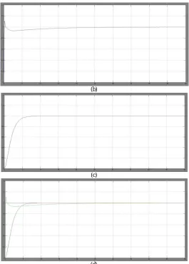
(b)
(c)
(d)
Fig 4: (a) Combined Simulation Diagram Of PID And IMC Controllers, (b) Simulation Graph of PID Controller,(c) Simulation Graph of IMC Controller,(d) Combined Simulation Graph of IMC and PID Controller
The above are the simulation response of the process under study, where the controller response of PID and IMC are studied.
S.No Controller
Rise Time
(sec)
Overshoot (%)
Settling Time
(sec)
1 PID 28.94 5.129 596
2 IMC 40.9 4.103 450
Table 1.Comparison for the Above Result
V. CONCLUSION AND FUTURE WORK
controller. Thus some of the other advanced controllers such as MPC controllers can be implemented for the process to obtain a faster response clearly.
REFERENCES
[1] EC, Draft proposal for a European parliament and council directive on waste electrical and electronic equipment, European Commission (EC) Report, Brussels, Belgium, 2000.
[2] J. Cui, E. Forssberg, Mechanical recycling ofwaste electric and electronic equipment: a review, J. Hazard. Mater. 99 (3) (2003) 243–263. [3] EPCEU, “Directive 2002/96/EC of the European Parliament and of the Council of 27 January 2003 on waste electrical and electronic equipment (WEEE), Off. J. Eur. Union L37 (2003) 24–38.
[4] SVTC, “Just say no to E-waste: Background document on hazards and waste from computers, 2007-11-07, http://svtc.igc.org/cleancc/ pubs/sayno.htm.
[5] X. Niu, Y. Li, Treatment of waste printed wire boards in electronic waste for safe disposal, J. Hazard. Mater. 145 (3) (2007) 410–416. [6] J.Williams, L.H. Shu, Analysis of remanufacturer waste streams for electronic products IEEE International Symposium on Electronics and the Environment, pp. 279–284.
[7] ISRI, Scrap recycling: where tomorrow begins, Institute of scrap recycling industries Inc. (ISRI) Report, http://www.isri.org/isri-downloads/ scrap2.pdf, 2003-11-06, Washington DC, USA, 2003.
[8] J.E. Hoffmann, Recovering precious metals from electronic scrap, Jom-J. Miner. Met. Mater. Soc. 44 (7) (1992) 43–48.