Study of Dynamics of a Tube Array under Cross Flow by means of CFD-
Simulation
Mingmin Ren and Jfirgen Stabel
Framatome ANP GmbH, Erlangen, Germany
ABSTRACT
Flow-induced vibrations of fuel assemblies in an operating reactor are one of the main causes of fuel rod fretting failures. Therefore, to understand the mechanism of flow-induced vibration of tube array will help us to improve the fuel rod support design to prevent the fuel rod fretting failures. In this paper a Computational Fluid Dynamics (CFD) model has been presented for the simulation of fluid dynamics of tube array in a cross flow. The verifications of the CFD model have been performed in comparison of the experimental results.
First, we use this CFD model to calculate the added mass coefficients of a 4x7 tube array in a channel. One of the middle tubes is moving with a predefined sine function while all of the rest tubes are in rest. All fluid around the tubes in the channel is modelled with fluid cells by the CFD code STAR-CD. A non-linear k-g turbulent model has been used in the transient analysis. After each time step, the fluid forces on the tubes are calculated, the middle tube is moved with a predefined sine function, the mesh of the CFD model is then adapted and the boundary conditions on the moving tube are updated with the velocities of the tube motion. The added mass coefficients are calculated and compared with the experimental data. A good agreement has been achieved between the CFD simulation and the Experiments.
Then, the fluid force coefficients of a 4x7 tube array in a channel are calculated by means of the CFD model. Reduced velocities between 1.5 and 10 and Reynolds number between 6000 and 24000, based on the flow bundle gap velocity, have been used in the CFD simulations. The frequencies of the tube vibrations are 2.5 Hz and 4.0 Hz, respectively. The fluid force coefficients in dependence on the reduced velocities are compared with the data from the experiments [4]. The comparisons of magnitude of fluid force coefficients with the data from Tanaka's experiments show a good agreement between the CFD simulation and the Experiments. The calculated phase angles agree well with the experimental data in lower reduced velocity region. With the increasing of the reduced velocity, the calculated phase angles show more volatile than the experimental ones.
Using this CFD model the fluid force coefficients of a tube array in a cross flow can be determined, then the equations of motion of a tube array can be solved and the dynamics of a tube array can be studied thoroughly. The improvement of fuel rod supports to prevent flow-induced vibration can be achieved in the early design phase.
I N T R O D U C T I O N
The fuel assemblies in an operating reactor are submerged in water and may experience various axial and cross flow. Fluid flow excites fuel rod vibrations and the fuel rod motions affect fluid pressure distributions and fluid forces on fuel rods. Such flow-induced vibrations could result under certain conditions, for example if the ratio of fluid force to fuel rod support damping is sufficiently large, in fuel rod vibration with a large amplitude, which could lead to fretting failures. Therefore, to understand the mechanism of the fluid dynamics of a tube array in a cross flow will help us to improve the fuel rod support design in respect of flow-induced vibration and fretting.
Generally fluid forces acting on a tube array in cross flow can be divided into three kinds of forces: an inertia force due to added mass of fluid, a damping force due to fluid viscosity, and a stiffness force due to the tube displacement. Under the assumption that the vibration amplitude is small and that a linear equation is applicable, the fluid force then can be written as follows:
F . P ' D 2 . .Cm .
2..[p D
. " . " V C~ J ( + P . . . " V2 C K . Y (1)2 2 2
SMiRT 16, Washington DC, August 2001 Paper # 1024
where
Cm
is the added mass coefficient, CD is the fluid damping coefficient, CK is the fluid stiffness coefficient, X is the displacement of the tube in X-direction, 9 is the fluid density, D is the tube diameter, and V is the bundle gap velocity.For the case of steady state vibration (constant vibration amplitude and frequency), the equation (1) can be reduced as:
F : 1 V2 I (2"Tc'f)2"D2
2"Tc'f'D
-~.p . . . .
C •
V2
+i'C o"
V
i..
--2"P"
V~ .C +i.--.Cz) +C .X
+Cx]'X
1
v c(v,) x
(2)
- - - _ _ o p o • o
2
From Eq. (3), one can see that the fluid force coefficient C(VR) is a complex number depending on the reduced velocity.
Under the assumptions that the fluid dynamic forces acting on the tube O, as shown in Fig. 2, are mainly induced not only by the vibration of tube O itself, but also by the vibrations of the neighbouring tubes L, R, U and D, and that the fluid dynamic forces are allowed to be superposed linearly, the fluid dynamic forces acting on a tube can be written by
1
.V2. Sj~=l(CXjx.Yj+Cxjr.y)
(3)F,
1
.V2.~j=(Crjx.Xj+Crjr.y)
(4)=7.p
where j = 1 - 5 denote the five tubes (O, L, R, U, D). The items
Cxjx,
etc. are complex fluid force coefficients. Thefirst suffix indicates the direction of the force, the second the position of the vibrating tube and the third the
direction of the tube vibration respectively. For example,
Cxer
signifies the fluid force coefficient in the X-direction induced by the right tube vibrating in the Y-direction. The fluid force corresponding to each fluid force
coefficient is then defined as F with the same suffices. For example,
Fxox
is expressed as follows:1
Fxo x = - 2 . p . V 2 .Cxo x . X o
(5)Z
As one can see, if the fluid force coefficients can be determined, then the equations of motion of a tube array can be solved and the dynamics of a tube array can be studied thoroughly. But unfortunately, it is very difficult to obtain the fluid force coefficients of a tube array in a cross flow. Analytical approaches for obtaining fluid force coefficient based on the potential theory are only applicable to obtain added mass coefficients and not applicable to obtain fluid damping and fluid stiffness coefficients.
A series of experimental investigations has been performed to obtain the fluid force coefficients of a tube array in cross flow. Experiments with a single row of tubes supported by elastic spars in
a cross flow have been performed by Connors [1] (see Fig. 1). He Flow Direction
foundthatthetubesabruptlystarttovibratewithlargeamplitudeata ~ ; ~ ; ~ ;
certain velocity in accordance with the well-defined system vibration
mode. He measured the fluid forces on one tube displaced by the C ) C ) ( ~ ( ~ @ C ) C )
observed vibration mode. He showed that at the critical velocity the Fig. 1 Single Row Tubes
The most extensive experiments for the measurements of fluid dynamic forces on a multi-row tubes under cross flow have been performed by Tanaka [3], Tanaka and Takahara [4], and Tanaka et al [5]. Under the assumption that the fluid dynamic forces on the tube O in a tube array are mainly affected by the vibration of itself, and by the vibrations of the upper and lower tubes U and R, as well as the left and right tubes L and R (see Fig. 2), the fluid dynamic forces on the tubes O, L, R, U and D in a square tube array with pitch-to- diameter ratio of 1.33 and 1.42 were measured in the experiments. Their experiments show that the fluid force coefficients can be regarded as a function of the reduced velocity VR in a Reynolds number range from 6000 to 24000. The critical flow velocities have also been determined for the tube array vibration in water and in air.
Flow Direction
®
©
oo@@ x
o
0 0 0 @
o o o o o Y o o
Fig. 2 Multi-Row TubesIn this paper a CFD model has been developed for calculation of fluid force coefficients of a tube array in a cross flow. The results from the CFD simulations are compared with experimental results and discussed here.
Added Mass Coefficients
First we develop a CFD model to calculate the added mass coefficients. This CFD model consists of a 4x7 tube array in a channel. The tube diameter is 30 mm and the pitch-to-diameter ratio is 1.33. The channel width is 280 mm. This is the same geometry as used in Tanaka' experiments [4]. The tube O is vibrating with a constant amplitude A and frequency f in still water while all of the other tubes are in rest (see Fig. 2). All fluid around the tubes in the channel is modelled with fluid cells by the CFD code STAR-CD. A non-linear k-~ turbulent model has been used for turbulent fluid flow in the transient analysis. After each time step, the fluid forces on the tubes are calculated, the tube O is moving with a predef'med sine function, the mesh of the CFD model is then adapted and the boundary conditions on the moving tube are updated with the velocities of the tube motion.
By setting flow velocity V = 0 in Eq. (1), the fluid dynamic force can be written as follows:
o r
F = 1 - ~ . p . D2 . C .J( . . . . 2 P .1 D 2 C m A (2 ~r . . . . . .
f)2 X
- 2 . F
C,, = D2 . . (6)
p . .A.(2 n"
f)2.X
The fluid forces acting on the tubes are calculated from the CFD model. Using Eq. (6) the added mass coefficients are determined and listed in Table 1. The values from the CFD simulations are in good agreement with the one from Tanaka's experiments.
Table 1. Comparison of Added Mass Coefficients
Experimental Data CFD-Simulation
Cm,xox 2.058 2.211
Cm,XLX -0.511 -0.485
Cm,xt~x 0.565 0.671
Cm,XDX 0.558 0.618
Cm, vov 2.121 2.262
Cm, YL Y 0.605 0.723
Cm, YU Y -0.465 -0.446
FLUID F O R C E C O E F F I C I E N T S
Then, we use the above developed CFD model to calculate the fluid force coefficients of a 4x7 tube array in a cross flow. The tube diameter is 30 mm and the pitch-to-diameter ratio is 1.33. The tube O is vibrating with a constant amplitude A = 30 mm, which is 10% of the tube diameter. All of the other tubes are in rest (see Fig. 2). Again, all fluid around the tubes in the channel is modelled with fluid cells by the CFD code STAR-CD. A constant flow velocity is applied at the inlet boundary. A non-linear k-~ turbulent model has been used for turbulent fluid flow in the transient analysis. After each time step, the fluid forces on the tubes are calculated, the tube O is moving with a predefined sine function, the mesh of the CFD model is then adapted and the boundary conditions on the moving tube are updated with the velocities of the tube motion. The CFD simulations have been performed with the reduced velocities between 1.5 and 10 and Reynolds number between 6000 and 24000, based
on the flow bundle gap velocity. These are corresponding to the experimental conditions of Tanaka. The
frequencies of 2.5 Hz and 4.0 Hz are used for the vibration of the tube O respectively.
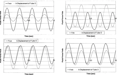
Typical time histories of fluid forces and displacement of the vibrating tube are shown in Fig. 3. Normally there is always a phase angle between the fluid force and the tube vibration. Applying the Fourier analysis to the calculated time histories of fluid forces, the magnitudes of fluid force and phase angles are determined from the fundamental Fourier coefficients. A positive value of phase angle denotes that the fluid force leads the tube displacement.
I' [_Fxox .... x-o,s0,ace ento, xubeo I ...
Time [sec]
. . . i
- - F x u x - X-Displacement of Tube 0 I
/
i
/
i
J
\/
\J
L/
\J
. . . Time [sec]
/\
/ \
/ \
/ \
/ i
/'
/
I
/\
i ~ J ', i ',. i
i
i
!
',~
i
i
i
'~
- - F x l x of Tube 0
... ... X-Displacement . . .
Time [see]
. . .
i
- - F x d x ... X-Displacement of Tube 0 l ... I
Time [see]
Fig. 3 Time Histories of Fluid Forces and Displacement of the Vibrating Tube
35 1 ... ~ ... ] --O-CFD-Simulation, 2.5Hz Ii
30 ~ . . . -t -O-CFg-Simulation, 4.0 Hz
|
25
"6 2o
~ lO
5
0 ,
2 3 4 5 6 7 8 9 10
60
'~' 50
Q
.~. 40
o
~ 30
'6
~ 20
e~
< 10
m
" 0
-O--CFD-Simulation, 2.5 Hz ... - ~.~
-O- CFD-Simulation, 4.0 Hz ~ i
Tanaka's Experiments ^ / i
. i
u
... c~ i
.."" WI i
i , }~ i , i i i ,
lb
- 1 0 ... i
Reduced Velocity
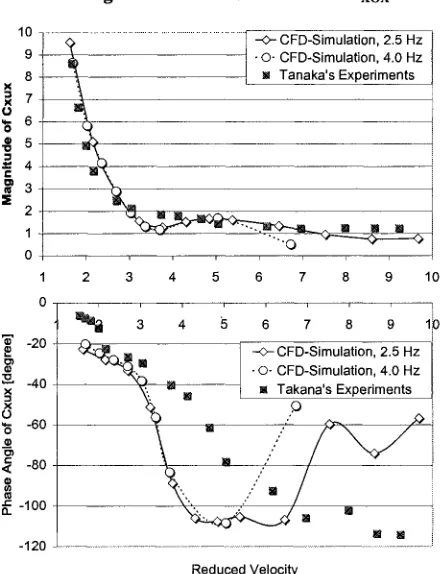
Fig. 4 Fluid Force Coefficient Cxox
~' -20
.-a. -40 =x
X
O -60
< -80
"= -100
Q.
... ~ - ... ~ CFD-Simulation, 2.5 Hz • O- CFD-Simulation, 4.0 Hz ~= Tanaka's Experiments
m
, i i i i , ,
-120
2 3 4 5 6 7 8 9 10
i i , i J , , 1
3 4 5 6 7 8 9 1~
~ ~ ; O . . , ---I --O--CFD-Simulation, 2.5 Hz i
~ . m
. ~ / -O-CFD-Simulation, 4.0 Hz
~., " m | I Takana's Experiments
' ,(~ ill ,,"
m ,'~
II Im
Reduced Velocity
Fig. 6 Fluid Force Coefficient Cxux
9
8
_x 7
~6
o 5
0
~ 4 ~ 3
=E 2 1 0
-O-CFD-Simulation, 2.5 Hz m
~~==i © CFD-Simulation, 4.0 Hz
• _ Tanaka's Experiments _ ~ f
"t ,~-N m
,
~
1 2 3 4 5 6 7 8 9 10
50 ...
0 . . . .
2 3 4 5 6 7 8 9 ~1.0
-50 --O--CFD-Simulation, 2.5 Hz a
-©- CFD-Simulation, 4.0 Hz Tanaka's Experiments
-100 m ~
-150
-200 ...
Reduced Velocity
Fig. 5 Fluid Force Coefficient CxLx
10 9 8 7 6 5 4 3 2 1
... ~ ... " ~ © ~ Tanaka's CFD-Simulation, CFD-Simulation, Experiments 4.02.5 Hz Hz
~ , " ' : ~ ~ - ' ~ ' ~ - ~
0
1 2 3 4 5 6 7 8 9 10
120 ...
--O-CFD-Simulation, 2.5 Hz A
-O- CFD-Simulation, 4.0 Hz ,H'
100 M_ Tanaka's Experiment~ .O ~ /
80
'.. • ,...,.,'~"
20 ~ ~ ~ - " "' =~ i
0 j ~ j j j ~ ~ j
1 2 3 4 5 6 7 8 9 10
Reduced Velocity
The comparisons of magnitude of fluid force coefficients with the data from Tanaka's experiments show a good agreement between the CFD simulation and the Experiments. The calculated phase angles agree well with the experimental data in lower reduced velocity region. With increase of the reduced velocity, the calculated phase angles show more volatile than the experimental ones.
CONCLUSION
A CFD model to simulate the fluid dynamics of a tube array in a cross flow has been developed. This CFD model has been verified by comparisons of the experimental data from Tanaka [3].
First, the added mass coefficients of a 4x7 tube array in a water channel have been calculated by means of the CFD model. In comparison with the experimental data good agreements have been achieved (see Table 1).
Then, the fluid force coefficients of a 4x7 tube array in a cross flow have been calculated. The CFD simulations have been performed with the reduced velocities between 1.5 and 10 and Reynolds number between 6000 and 24000, based on the flow bundle gap velocity. The frequencies of the tube vibrations are 2.5 Hz and 4.0 Hz, respectively. The fluid force coefficients in dependence on the reduced velocities are compared with the data from the Tanaka's experiments. The comparisons of magnitude of fluid force coefficients with the data from Tanaka's experiments show a good agreement between the CFD simulation and the Experiments. The calculated phase angles agree well with the experimental data in lower reduced velocity region. With the increasing of the reduced velocity, the calculated phase angles show more volatile than the experimental ones.
Using this CFD model the fluid force coefficients of a tube array in a cross flow can be determined, then the equations of motion of a tube array can be solved and the dynamics of a tube array can be studied in detail. The improvement of fuel rod support design with regard to prevent flow induced vibration can be achieved in the early design phase.
NOMENCLATURE
C
CD
CKCm
D F f V VR X Pfluid force coefficiem (dimensionless) fluid damping coefficient (dimensionless) fluid stiffness coefficient (dimensionless) added mass coefficient (dimensionless) tube diameter
fluid dynamic force tube vibration frequency flow bundle gap velocity reduced velocity (V/(Df) ) displacement of tube fluid density
R E F E R E N C E S
1. Connors, J. J., "Fluid elastic vibration of tube arrays excited by cross flow", Symposium of flow-induced vibration in heat exchangers, ASME Winter Annual Meeting, December 1970
2. Blevins, R. D., "Fluid elastic whirling of a tube row", Joumal of Pressure Vessel Technology Transactions of the ASME, 1974, vol. 96, pp. 263-267.
3. Tanaka, H., "Study on Fluidelastic Vibration of Tube Bundle", Nihon KiKai Gakki Ronbunshu, or Japan
Society of Mechanical Engineering, 1980, Section B, Vol. 46, pp 1398-1407
4. Tanaka, H. and Takahara, S., "Fluid Elastic Vibration of Tube Arrays in Cross Flow ", Joumal of Sound
and Vibration, 1981, Vol. 77, pp. 19-37