20th International Conference on Structural Mechanics in Reactor Technology (SMiRT 20) Espoo, Finland, August 9-14, 2009 SMiRT 20-Division 2, Paper 2503
Structural Integrity Assessment of a Rupture Disc Housing with Explicit
FE-Simulation
Christian Bergler
a, R. Trieglaff
aa
TÜV Nord SysTec GmbH & Co. KG , Hamburg, Germany, [email protected]
Keywords: rupture disk, LS-Dyna, explicit dynamics, impact simulation, ALE.
1
ABSTRACT
Structural integrity of reactor components is most generally proven based on stress calculation without or with limited plastic deformation. Dynamic problems may often conservatively be verified with load factors on quasi-static calculations. However dynamic and highly nonlinear explicit Finite-Element (FE)-simulation may give a deeper insight to a physical problem or may be useful if a conservative approach cannot be easily made. Therefore it can give an important contribution to the assessment of safety aspects in case of large deformations and short time dynamic loads during faulted or emergency plant conditions. In this paper, the impact-simulation for a rupture disk housing is taken as an example to discuss safety factors complying with current regulations and to describe sources of conservatism depending on the level of detail of the idealisation.
2
INTRODUCTION
Low pressure turbines of PWR power plants are generally equipped with rupture discs to avoid a pressure overload that could lead to a damage of the turbine and the condenser.
To avoid an intake of air in case of a defect or imploded rupture disc membrane, a freely supported plate in the rupture disk housing withstands the vacuum forces. In case of a rupture disc burst caused by an excess pressure in the turbine, the plate is accelerated and impacts the retaining clamps mounted on the housing.
The aim of the investigation is to assure the structural integrity of the rupture disc housing in compliance with essential safety standards. Moreover the calculations are taken as an example to discuss general aspects and safety margins for short time dynamic and impact simulation.
The calculations described here have been carried out with LS-Dyna based on explicit time integration. Beside a purely Langrangian calculation an arbitrary Lagrange Eulerian (ALE) approach to capture the fluid structure interaction, as e.g. used in the automotive industry for airbag inflation simulation, has been tested. Further applications for explicit FE-simulation related to nuclear energy safety concerns can be found e.g. for dropped load impact, plane crash, explosion shock waves and container (spent fuel cask) certification. Also for postulated pipe breaks the dynamic effects on the neighbouring systems may be simulated
3
IMPACT SIMULATION
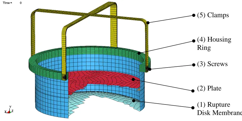
Figure 1 shows the geometry of the rupture disk housing. After the burst of the rupture disk membrane (1) the outtake of steam accelerates the plate (2) that impacts the clamps (5). The full geometry of the housing has been modelled to assess different unsymmetric impact conditions. The clamps and the housing ring (4) are modelled with solid elements; the rupture disk membrane, plate and the cylindrical part of the housing are modelled with shell elements. The screws (3) attaching the clamps to the housing-ring are modelled simplified as solid head and bolt tied to the ring. Pre-stress at the bolts is applied via the *INIT-IAL_STRESS_SECTION [1] keyword.
Figure 1. FE-Model of the rupture disk housing
Material Modelling
For the clamp material the isotropic elastic-plastic, rate dependent material model *MAT_124 (*MAT-_PLASTICITY_COMPRESSION_TENSION) has been used. For *MAT_124 different true stress vs. logarithmic plastic strain curves may be applied for tension and compression. As typically used for metallic parts, the elastic-plastic material model *MAT_24 (*MAT_PIECEWISE_LINEAR_PLASTICITY) with arbitrary stress versus strain curves and arbitrary strain rate dependency has been used for all other parts of the structure. In order to account for necking, material degradation and damage may be induced via the plasticity load curves by reducing the stress when uniform strain is exceeded.
Minimum material strength values have been applied for the clamps. For the impacting plate mean material strength data has been used, as minimum values may potentially be non-conservative.
3.2 Impact Simulation - Lagrange
For the purely Lagrangian impact simulation an initial velocity has been applied to the plate. Beside an impact position with a zero horizontal angle an arbitrary initial angle position of the plate before the impact has been investigated. A constant pressure is applied to the plate during the impact, to account for the impulse of the steam flow.
(5) Clamps
(4) Housing
Ring
(3) Screws
(2) Plate
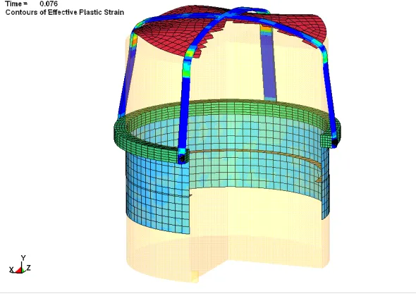
Figure 2. Deformed shape after impact – plastic strains at the clamps and stress in the screw at max. loading
Simulation Results
Maximum plastic deformation occurs at the arcs of the clamps and at the drill holes. For the nominal burst conditions the minimum failure strain is not exceeded.
The maximum stresses at the screws calculated by section forces or directly taken from the stress output are compared to the maximum allowable stresses. In this case for nominal burst conditions, the screws are not predicted to fail.
3.3 Impact Simulation - ALE
The impact velocity of the plate may conservatively be determined by basic equations. The precise prediction of velocity and impact position of the plate underlies an uncertainty depending on the conditions of the membrane burst and the steam flow.
The dynamic effects of the steam flow can be simulated using the ALE capability within LS-Dyna. Thus the applicability of basic formulas may be verified and parameters as steam flow velocity vector and burst initiation may be varied. In our simulation the thermodynamic state of the steam is defined by the equation of state *EOS_IDEAL_GAS together with the material card *MAT_NULL. The *BOUNDARY_-AMBIENT_EOS has been used for ‘reservoir’ elements to predetermine the thermodynamic state inside the turbine throughout the simulation time. The outflow velocity can be controlled by a function for the *BOUNDARY_PRESCRIBED_MOTION card. As a simplification the air above the membrane is modelled as *INITIAL_VOID. The mass of the steam is transported from element to element in the fixed Eulerian mesh and the contact to the structure is defined by *CONSTRAINED_LAGRANGE_IN_SOLID, in this case penalty based with erosion.
Simulation Results
Figure 3. Burst of the Membrane.
Figure 4. Acceleration of the plate after membrane burst – velocity vectors of the fluid.
Figure 5. Deformed shape after impact – plastic strains at the clamps
4
SAFETY MARGINS
Generally safety factors have to be applied or a strain criterion has to be met in order to account for the uncertainties of a simulation. For the described loading scenario the following uncertainties may lead to an inaccuracy of the predicted results:
- deviation of material properties
- manufacturing tolerance, manufacturing defects
- flow boundary conditions and parameters
- ..
For the rupture disk housing potential defects might occur at the following locations:
Clamps (arcs and drill holes):
Rupture of the clamps is induced if the plastic failure strain is exceeded. Generally a failure strain criterion should account for triaxiality, because for specific load cases and geometries failure may occur due to a hydrostatic spall pressure without exceeding the uniaxial quasi-static failure strain. So it generally has to be checked if the available plastic failure strain value is valid for an acceptance criterion to prove the structural integrity. Also it should be noticed that failure strains in material standards are generally conservative and do not account for local phenomena as necking etc.
Screws:
In this case failure of the screws is assumed, when a maximum allowable bolt-stress is exceeded. For scenarios, where the early failure of fasteners is not conservative, failure loads have to be mean or maximum values.
types (considering large deflections or not). Moreover the regulations contain partly varying rules to determine yield stresses and safety factors for the relevant service levels.
According to KTA 3201.2 [2] and 3204 [3] an elastic-ideal-plastic material law is applied for limit load calculations with the yield stress and the safety factor depending on the operating condition. Nevertheless for specific load cases in explicit dynamic simulations a conservative elastic-ideal-plastic material curve may lead to an unrealistic overall response of the structure. Also minimum material values are not necessarily conservative if e.g. applied for impactors. In ASME VIII-2 [5] true stress vs. strain curves are applied for large deflection analyses with a safety factor of 2,4 for design load cases.
If structural parts simply have to withstand a dynamic load regardless of the residual deformation, a service level D safety margin for a calculation with a conservative realistic material stress-strain curve appears to be valid. Taking into account the different requirements for Plastic Collapse simulations a safety factor of 1,5 on the relevant load appears adequate to prove the integrity of structural parts (except screws) at short time dynamic loading. The proposed load factor on the relevant load corresponds to a factor on the introduced energy to be absorbed by the system.