Assessing the Effect of FRP System On
Compressive and Shear Bending Strength Of
Concrete Elements
Seyyed Mohammad Amin Seddigh Marvasti
*1, Babak Beheshti
2, Hamid Chegini
3, Mohammad
Taghipour
4*1
Civil Engineering, Non-Profit Institution of Higher Education, ABA, Abyek, Qazvin, Iran 2
School of Mechanics, Science & Research Branch of Islamic Azad University, Tehran, Iran 3
Director of Graduate Studies, Non-Profit Institution of Higher Education, ABA, Abyek, Qazvin, Iran 4
Research Assistant of Non-Profit Institution of Higher Education, ABA, Abyek, Qazvin, Iran
ABSTRACT: Behavior of reinforced concrete structure depends on correct behavior of beam and column so much. Access to necessary bending strength, prevention of changing permanent configuration and prevention of bending failure of section cause to pay attention making resistant of concrete elements specially bearing beams of structures .with due attention to importance of subject, this research pays to assess effect of FRP system on pressure and cutting and bending strength of concrete elements. Therefore the aim of this research is decomposition behavior of concrete barrage under it is weight force .For this reason ,making Abaco software ,was used .In the first step ,we will assess four models with fixed section and lengths of 20,30,40,50,meter .In the next step,we will assess three models with length 30meter ,and reformed section surface .results showed ,strengthening of columns in area of connection causes to increase 10.5 percent of lateral stability load .Also strengthening of FRP in connection cause to increase ductility in frame .
KEYWORDS: FRP, Reinforced Concrete, Bending Strength, Shear Strength, Compressive Strength,Making Abaco
Software.
I.INTRODUCTION
Assessment and selection present repair materials is a difficulty stage to repair and remaking .A lot of new repair materials cause to develop suggested companies of usage services,which causes to create competition fields .To repair ,keeping and remarking there is not any special rule, also there is not any standard and procedure which give cover for using the materials(1).
Nowadays development and improvement of knowledge and technology,effort for coexistence of human societies with natural phenomena ,like earthquake which it is demolition signs,treats human life .It has made it closer to it is purpose(12).
Vibratory area of Iran also is recovered the happening of repeated earthquakes on it is here and there in it is history of thousands year old and beside civilizations and affluences it is head has sinked in earth ,and from growth and renewed affluences second life has been created .
This ups and downs has arrived to second life by appearing noticeable growth in engineering knowledge of earthquake and seismology ,by enjoyment of worthy scientific capitals of scientist and connoisseur professors ,also in endeavor efficient students and researchers (2).
around section ,external pre weave of members,shortening space of supports and lately also twisting round of members by FAP(7).
FRP is a composite with high tensile strength which has spread usage in making resistant of concrete structure in front of earthquake force because of high tensile strength down weight ,and suitable durability,(in front of corrosion) (3 and 4) .
On a side usual movement of science on structure –earthquake engineering area has caused to take profit for making better and making resistant from new ways and new materials in recent years that yet have not had so much background in making building industry among these technologies FRP (Polymer Composite Materials by Fibers)care enjoying from special place as far as some of experts opinion ,FRP must be named third millennium materials which opened a new hatch in progress of civil engineers ,in a species that today several structures are made resistant by this technology (5).
Behavior of reinforced concrete structure so ,much depend to correct behavior of beam and column.Assess to necessary bending strength ,prevention of bending failure of section and prevention of changing permanent configuration cause to pay attention making resistant of concrete elements specially bearing beams of structure (11).In this article pays to assess effect of FRP system on pressure and cutting and bending strength of concrete elements .
II.THE MEANING OF FRP
This word is abbreviator of word ,(Fiber Reinforced Polymer or Plastic ) FRP can be used to repair or strengthening and making better kinds of concrete structures wit installing on surface (Slabs and beams ,column , bearing walls,shenages and fondasion )and in residential ,official and commercial building ,industrial buildings,machinery supports and heavy installation ,watery structures such as barrage ,canal ,and –etc ,patch and rail bridges ,water and liquids sources and stores ,silos and cooling towers(6).
In other words ,a composite and compound material is applied that has formed from a matrix and a strengthened material in form of fibers.matrix is compound of a resin (polyster,epoxy,… )and suitable added materials which use to decrease cost of matrix and improve characteristic of resin from them .In composites strengthened material caused to create high mechanical quality ,while the matrix has the role of translocation of external load to fibers and protection of them in front of aggression external environment .Fibers in composites have allocated to themselves so much and original duty of endurance load is charge of them .Kind of fibers ,suitable amount of them for usage and method of putting them can be affected on tensile , compressive ,bending ,fatigue strength , transition coefficients of heat and electricity and the most important of all price which each of mentioned factors can be an assigned factor for refusing or accepting kinds of various fibers(13).
Mechanical benefits of fibers,formation of fibers(for found two directions fibers)and paste are used to original factors in physical efficiency of FRP composites .For this reason composites are named in attention to kind of used fibers in them .Usual fibers that are discussed in produce composite materials are consisted of :glass fibers(GFRP) ,Carbon(CFRP) Aramid (AFRP)and (VFRP).
FRP system is defined like this,thatfibers and resins are used to produce several compound layers .In a way that usage resin use to stick several compound layers on surface of following concrete and covers for protecting of combined materials .Usual covers that are used to apparent beauty are taken in consideration as part of FRP system(14).
III.EXPERIENTIAL BACKGROUND OF RESEARCH
To start work , first we point to a research work that was done in Hong Kong by Chrisopher et al .In 2006 .In this test reinforced concrete beam is chosen in dimensions of length 3.6m and in dimensions of 150*400 mm and for strengthening this beam from carbon fibers is chosen in thickness 0.44 mm which it is Medlalsetisiteh equal to 235 GPA and it is tensile strength equal to 4.2 GPA(8)
were stayed for presentation of failure early time by nails in three point which two first nails in length 50.8mm and third nail in size 30.5mm.(9)
In another research which is done in Singapore university by Mr Mohammad Maaleg et al . in 2001 , a set of concrete beams are made in dimensions of 150*115 mm and length 1500 mm which inside beam was used of 2 bars in above beam and 3 bars in down beam which diameter of each bars was equal 10 mm were used to make rein forced beams.And position to become commercial of bars was equal fy=535 MPA and stirrup in diameter 6 mm in distance of 60 mm was used to make reinforced cutting beam which it is following strength also was equal FY= 365MPA
IV.STAY OF DOING RESEARCH WORK
In this project , the aim of concrete barrage behavior analysis ,is under it is weight force .for this reason ,making Abaque software is used ,kinds of processing in Abaqus content to three stage by some files with each other 1- the stage of pre processing (Abaqus /CAE) 2- The stage of processing (Abaqus standard /Explicit ) and 3- The stage of post processing (Abaqus /viewer)
In the first stage we will assess four models with fixed section and lengths of 20,30,40,50,m.Then in the next stage we will examine three models with length of 30 m , and reformed section surface .
1- Module Part
This model contains 2 parts .The first part is concrete frame and second part is mesh reinforcements .We name the first part frame and the second part Grid .This kinds of parts have been made by three parts (Construction of column geometry,Construction of beam geometry ,Construction of longitudinal bars geometry) .This part will be made by helping the item create pare .Solid Almans will be used to make model in three dimensional area .This Alman has three degree of transition freedom. Also kind of Almans will be taken in to consideration like deformable .
2- Module Property
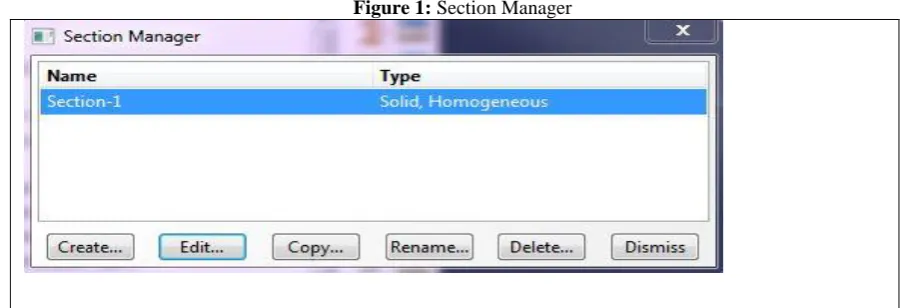
materials will be made and will be appropriated to parts .In first step , the kind of required material will be made to help item create material .Frame is a kind of concrete and will have nonlinear behavior .For this purpose we will be satisfied with recording density ,elastic modulus and poisons ratio and plastic behavior of concrete ,then kind of the environment will be defined in regard to be homogenous by create section item of kind of environment . figure1 said that all sections will be from kind of homogeneous with solid Almans.
Figure 1: Section Manager
3-module Assembly
In this modulus ,resting position of parts will be defined as compared to each other .For this purpose ,we will use of create instance selection.In this making model first concrete parts containing beam and column will be put near each other and made them marge.The mesh reinforcement will be made Marge by longitudinal bars.At the end two parts of concrete frame and mesh reinforcement will be put at the suitable place as compared to Global coordinate machine.. 4-Module step
In this modules ,kind of related analysis must be defined .In first stem create step selection is cut until kinds of analysis are defined in it . In this making model both two frames will be setteled under similar wheeled loading ,for this reason general static analysis will be used .Also this selections for showing color cantor will be made active in field out putpart.Also , in next stage , history out put section will be used to getting the data in some spots as compared with time .It is necessary to say that before this section ,this sets must be assigned which results are important in those spots for us .At set in the name of Displacment in the parts of roof and another set in the name of base shear will be defined in place of supports ,because of drawing of Histerziscurve. Then this sets will be used to assign changing place of frame and prop shear in history output .
5-Module interaction
Interaction between parts will be assigned in this module .The only explanatory interaction is friction connection between mesh reinforced and concrete .For this purpose ,we will used of Embedded selection.In this state ,mesh reinforcement will be chosen as Embedded and also concrete frame as host.
6- Module Load
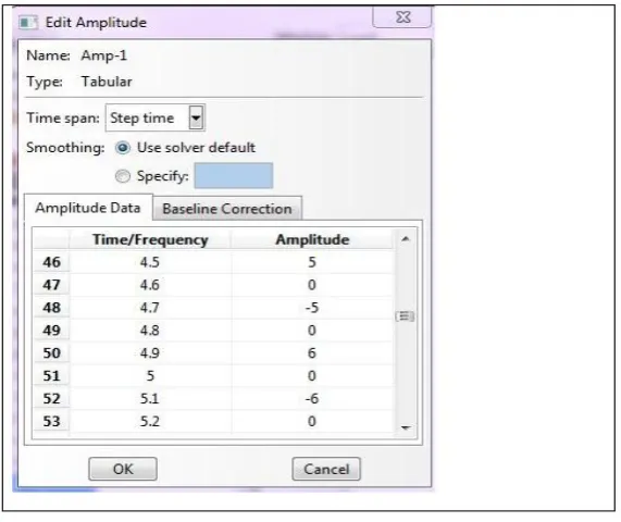
Boundary conditions and loading will be defined in this module .first boundary conditions will be defined .We click on create Boundary condition .Part prop of columns will be controlled according to figure like restraint .Methods of boundary conditions is in the manner that three degree of transfer freedom .As for the kind of loading boundary conditions will be applied like changing of cyclic transfer place to frame.For this purpose also we click on create Boundary condition selection .Kind of cyclic losding will be delineated in amplitude chart .Also ,as for direction of coordinates Pivots ,gravity acceleration will be interned like figure.
7- Module Mesh
Making gait of parts will be done in this module .In first step size and the number of gait will be characterized by helping the seed edges selection and in continuance ,making gait will be done by mesh part instance .After making gate ,kind of gate will be studied by using of verify mesh selection that gait does not have error or earning .Gaits with error prevention of analysis and gaits with warning will be caused to create error in results .Kind of Alamns is in concrete frame of C3D8R.The important point is necessary to regular making gait which form partition . when the model is brown means that making gait is weak and after partition ,model will be become green which meant regular making gait.
8.Module Job
This module is related to processing of model and software will start to solve the defined numeral problem .In first stage ,great job will be chosen and in next stage with choosing the submit selection , soft ware will be started to analysis .By choosing the monitor selection , we can look to analysis process ,and at the end after arriving the condition to complete choose the results selection until results have been shown.
Figure 3: job monitor
V.FINDINGS
1 – Behaviors cure of materials
Table 1: Behavioral Characteristics of Style Bar
Elastic Range Plastic Range
Poisson`s Ratio Elastic modulus Strian Stress(MPA)
0.3 210 0.00135 300
0.1865 300
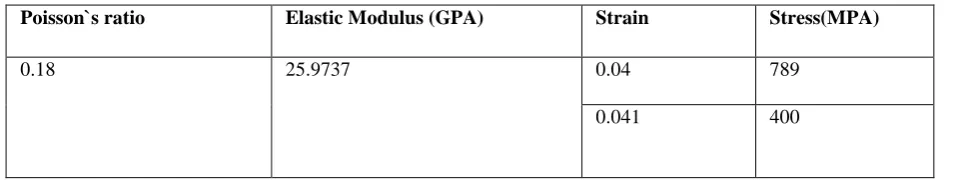
FRP bars will be lacked of plastic ratio and after elastic behavior will be involved failure . Table 2:Behavioral Characteristics of FRP bar
Poisson`s ratio Elastic Modulus (GPA) Strain Stress(MPA)
0.18 25.9737 0.04 789
0.041 400
Behavioral characteristics of concrete are in following :
Table3 :Characteristics of elastic stage of concrete
Poisson ratio Young's modulus (MPa)
0.18 18011.48
Table 4: Characteristics of Plastic Stage of Concrete.
Viscosity Parameter K Fb0/fc0 Eccentricity Dilation Angle 0.001 0.666 1.16 0.1 30.5
. . . . 0.0013 0.43 0.0014 0.40 2-Loading
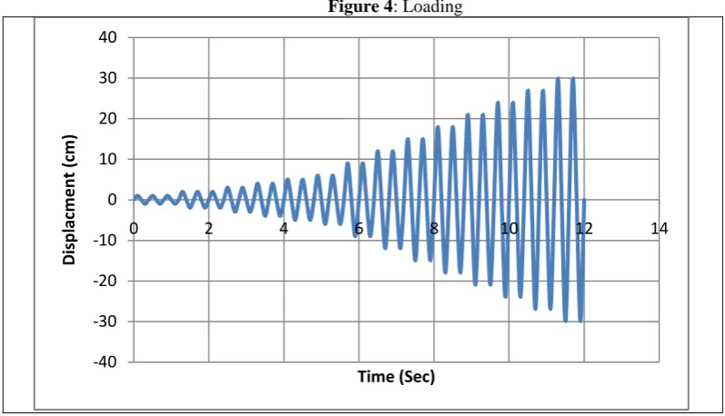
Loading is like increasing cycle .This changing place will be entered slowly from amount of 1 centimeter to 30 centimeter in roof .Where as cycling loadings do slowly ,kind of analysis will be down like static . In this case ,effects of speed and rush is zero and structure will not be stood under vibration.
Figure 4: Loading
VI.CYCLIC LOADING
In this section ,all exits of Abaqus software will be shown after analysis.Cyclic curve has been shown to two conditions of steel and FRP bar .Horizontal axis against changing of lateral place with structure and vertical axis is introducer of pier shear .surface under curve in each cycle is explanatory wasting energy of incidence to structure .whatever this surface is larger means that wasting energy is more bas happened in structure .In the case that steel bar is used in frame structure will be more shapeable and for some changing place ,pier shear will be experienced less . But in FRP bars because of increasing yield stress of that fragile behavior ,it is hardness will be increased and probable earthquake of structure will experience changing of lateral place less in floors . But pier shear more will be done on structure pier that it is results are larger stresses in structure .To arrive to more ductility ,the percentage of FRP can be decreased that it is result is economy in construction expense .
-40 -30 -20 -10 0 10 20 30 40
0 2 4 6 8 10 12 14
Figure 5: cyclic curve of FRP and steel bar
I n
following figures Maisez stress of concrete will be shown accompanied by FRP in various step.
S, Mises –Time 00
S, Mises –Time 01
-300 -200 -100 0 100 200 300
-40 -30 -20 -10 0 10 20 30 40
B
ase
Sh
e
ar
(k
N
)
Displacment (cm)
Steel
S, Mises –Time 02
S, Mises –Time 04
S, Mises –Time 05
S, Mises –Time 07
S, Mises –Time 09
S, Mises –Time 10
VII.CONCLUSION
Abstract of findings are presented there :
1- strengthening of columns in area of connection caused to increase 10.5 percent of lateral stability loud. 2-strengthening of FRP in connections cause to increase ductility in frame.
Injured buildings because of happening earthquake and /or buildings which are recognized weak in the manner that their first strengthening must be recovered and /or even their strengthening becomes more they are repaired and strengthened until endure the next earthquakes .The repaired buildings must supply the obligation of regulations .Anyway repairingand strengthening vibratory of a building may be more expensive The end decision about that whether repaired and making resistant are done ,or if do how is ,need to assess economical multilateral .Nowadays application of advanced composite materials is increasing in civil engineering for reinforcing and making resistant of structures.Composite materials are made from combination of two materials fiber and matrix that fibers are usually from carbon ,glass and aramid and matrix is from family of polymer matrixes like Apoksi. Composite materials will be had an assigned role for reinforcing of strategic structures specially marine structures and making resistant of executed reinforced concrete structures in earthquake area because of having variety and good benefits in near future .As yet performed examinations all were confirmatory to increase axial ,shear and bending strength of strengthened samples by composite fiber .Strengthened beams by CFRP and GFRP from bearing capacity (end strength ) show more suitable condition than beams without strengthening and also decreasing of changing the vertical figure while servicing and limiting width and spreading cracks in concrete is expected to more endurance
VIII.SUGGESTIONS
It is suggested that by doing following complementally research and taking enjoyment from results of this research a compressive model final from concrete beam and also strengthened concrete structures with FRP composite .
1-Using of FRP fibers in concrete members and putting it in corrosion areas.
2-Using perspired FRP system in concrete members and building perspired members by FRP system.
3-Using of various concretes like high strength concrete and self compaction concrete and strengthening them by FRP system.
4-Building various concrete parts like shear wall and reinforced concrete slab and strengthening them by using FRP system.
REFERENCES
[1] Hewlett, P.C.(1987), Material and techniques Keynote paper Structural Faults and Repair, London, 24. [2] Regulations for seismic design of buildings Standard (2008), edition 3.
[3] Supaviriyakit, T., Pornpongsaroj, P. and Pimanmas, A.,(2004), Finite element analysis of FRP-strengthened RC beams , Song klanakarin J. Sci. Techno, 26(4) : 497-507.
[4] Paulay, T. and Priestley, M.(1992), seismic Design of Reinforced Concrete and Masonry Buildings; John Wiley &Sons , New York. [5] MojtabaTaghaviAbrishami, seismic strengthening of reinforced concrete structures using composite
[6] Taljsten, B. Carolin, A.,(1999), Strengthening of a Concrete Railway Bridge in Lulea with Carbon Fiber reinforced Polymers –CFRP: load Bearing Capacity before and after Strengthening Technical Report 1999:18 Lulea University of Technology . Structural Engineering . 61pp. [7] An Lin Lu Zhito and Jin Zhiqiang (2001), The First Bridge Strengthening by CFRP Plate in china Elsevier Ltd. All right resaved.
[8] Bo Gao, Jang-Kyo Kim, Christopher K.Y.Leung,(2006) Optimization of tapered end design for strip bonded to RC beam Composites Science and Technology 66 (2006) 1266– 1273
[9] Lawrence C. Bank, DushyantArora,(2006), Analysis of RC beams strengthened with mechanically fastened ,FRP (MF-FRP) strips Elsevier .com /locate/compatriot
[10] Maalej, M. & Y. Bian.(2001). Interfacial shear stress concentration in RC beams strengthened in flexure with Externally-Bonded FRP. pp 519-526. In FRP composites in civil engineering. Vol. I.. Editor (J.G. Teng). Elsevier Science Ltd.
[11] Guide for the design and construction of Externally Bonded FRP system for strengthening concrete structure ACI440.2R(2002). [12] Smith,S.T., Teng, J.G. (2002)“ FRP-strengthened RC beams. I: review of debonding strength models”, Engineering Structures 2:395-385. [13] 13.Nanni, A., “concrete repair with Externally Bonded FRP Reinforcement (1995), concrete enternational, vol17,No. 6,june1995, pp . 22-26. [14] Nanni,A.,Focacci, And Cobb.C.A ,(1998) “ Proposed Procedure For the desin of RC Flexural Members strengthened With FRP Sheets