Mathematical Modeling of Grid Connected
PV System Using S-Transforms
J. Srinu Naik1, Dr. K. Chandra Sekhar2
Associate Professor, PNC&VIET, Repudi (V), Guntur (Dst), AP, India1
Professor, RVR &JC College of Engineering, Chowdavaram, Guntur (Dst), AP, India2
ABSTRACT: This paper presents the mathematical modeling of PV system connected to grid with S-transforms. Mathematical modeling of power electronic converters is an issue for power engineers from long time. Conventional modeling goes away from using transfer functions due to the involvement of high degree non-linearity in power converters. In this paper, mathematical modeling of grid connected PV system was developed using S-transforms. Three phase outputs were shown for grid connected PV system.
KEYWORDS:PV, Modeling, Power Converter,Grid.
I.INTRODUCTION
Reducing global warming, improved public health and environment quality, vast and inexhaustible energy supply, economic supply and stable energy supply makes renewable energy a prospect for electrical energy generation. Renewable energy is classified as energythat comes from resources like sun light (known as solar), wind, geo-thermal heat and rain that are constantly replenished.Renewable energy can serve as a replacement to electricity, motor fuels, ruralenergy and heating. Solar and wind are mostly used and solar is the dominant renewable energy source being used. Since the evolution of power electronic converters, engineers have tried to develop different mathematical models and analysis techniques with their respective control circuits for different power converters. Modelling based on small signal analysis was used most. This methodology uses power converter circuits for development of mathematical models. This method fails to predict the fast dynamics of the converters whereas they are very good in sensing slow dynamics.
Fig.1: System with PV integration to utility Grid
II.GRID CONNECTED PV SYSTEM
Fig.2: PV string equivalent circuit
Grid connected PV equivalent was shown in figure 2 and consists of current source, anti-parallel diode, shunt resistance due to leakage current and series resistance. Current through diode is Id and current from PV is Ipv. PV array is formed
by connecting all the PV strings in series. Each PV string looks like in figure 2. The current from PV cell is given by
= [exp( ( ))]−1 (1)
where k is Boltzmann constant, T is the temperature, Rs is the equivalent series resistance of the array, Rsh is the
shunt resistance of the PV array due to leakage current, I0 is the reverse saturation current of PV cell.
Generally the output of PV cell is connected to a DC-DC converter. The output of PV system will be a low-voltage output and this low-voltage output needs to be increased to a desired value. The DC-DC converter performs this task of step-up low voltage to required desired voltage.
III.TRANSFER FUNCTION DERIVATION
(a)The transfer function of the PV array current to the instantaneous power is given by
( ) ( )=
( ) ( )
( ) ( )=
( ) ( )
( ) ( )
( )
( ) (2)
=
( )
( )
( ) (3)
The transfer function from the solar panel’s input current to the output of the averaging module, P can be written as shown in eqn. (4)
=
( )
( )( )
( )
( )
(4)
Simplified transfer function for PV cell can be written as
(5)
(b)Transfer function of a boost converter:
Fig.3: Boost converter
Fig.4: Boost converter when switch is closed Fig.5: Boost converter when switch is open
When the switch position function is set to u = 1, we obtain, using Kirchhoff’s voltage and Kirchhoff’s current laws, the dynamics described by the following set of equations,
= (6)
=− (7)
When the switch position function is set to u = 0, we obtain the dynamics described by the equations,
=− + (8)
= − (9)
The Boost converter dynamics is then described by the following bilinear 1 type of system:
=−(1− ) + (10)
= (1− ) − (11)
However, transfer function of a boost converter in real time implementation can be written more precisely as shown in the below equation [4]-[6]
( ) = = (12)
Here, R is the output resistance seen by the dc-dc converter and can be written as shown in eqn.(13)
Fig.6: Block diagram of single phase inverter
(C) Figure 6 shows the system block diagram of the single phase inverter the input and output transfer function of inverter is:
( ) = ( )− ( ) (14)
The frequency transfer function can be expressed as
( ) = ( )− ( ) (15)
To determine the transfer function:
( )− ( )− ( )− ( ) = 0
(16)
( )− ( ) = ( ) + (17)
( )
( )= 1 +
( )
( ) (18)
( )
( )= 1 +
( )
( ) (19)
( )
( )= (20)
( )
( )= (21)
The overall transfer function of the system consisting of PV system, boost converter and the inverter can obtained by combining all the three individual transfer functions of PV system, boost converter and inverter as
( )=( )
( )( )
( )
( )
IV.MATLAB/SIMULINK MODEL AND RESULTS
Fig.7: Matlab model of overall system with PV system, Boost converter and inverter for grid connection
Fig.8: current waveform of the system
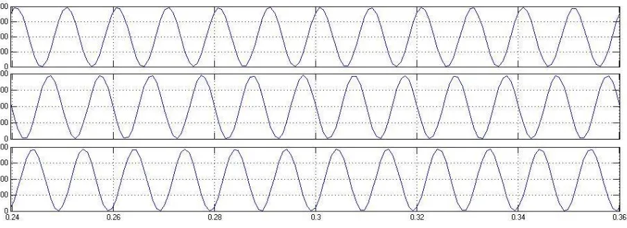
Fig.9: Power waveform of the individual three phases of the system
V.CONCLUSION
This paper presents the mathematical modeling of PV system connected to grid with s-transforms. For a long time, mathematical modeling of power electronic converters is an issue for power engineers. Conventional modeling goes away from using transfer functions due to the involvement of high degree non-linearity in power converters. This paper presents mathematical modeling of grid connected pv system developed using s-transforms. Complete modeling of PV system, boost converter and inverter were shown. The output currents and power of the grid were also shown which were obtained using mathematical modeling.
REFERENCES
[1] H. Sira-Ramirez, “A geometric approach to pulse-width modulated control in nonlinear dynamical systems,” IEEE Trans. Automat. Contr., vol. AC-34, no. 2, pp. 184–187, Feb. 1989.
[2] R. W. Erickson and D. Maksimovic, Fundamentals of Power Electronics, 2nd ed. Boston, MA: Kluwer, 2001.
[3] Mahdavi, J.; Emaadi, A.; Bellar, M.D.; Ehsani, M., "Analysis of power electronic converters using the generalized state-space averaging approach," Circuits and Systems I: Fundamental Theory and Applications, IEEE Transactions on , vol.44, no.8, pp.767,770, Aug 1997. [4] F. L. Luo, H. Ye , “Small Signal Analysis of Energy Factor and Mathematical Modeling for Power DC–DC Converters”, IEEE Transactions
on Power Electronics, VOL. 22, NO. 1, JANUARY 2007, pp. 69 – 79.
[5] F. L. Luo and H. Ye, “Energy factor and mathematical modeling for power dc–dc converters,” Proc. Inst. Elect. Eng., vol. 152, no. 2, pp. 191– 198, Mar. 2005.
[6] F. L. Luo and H. Ye, “Mathematical modeling for power dc–dc converters,” in Proc. IEEE Int. Conf. POWERCON’04, Singapore, Nov. 21– 24, 2004, pp. 323–328.
[7] S. Mazumder, M. Alfayyoummi, A.H. Nayfeh, D. Borojevic, “A Theoretical and Experimental Investigation of the Nonlinear Dynamics of DC-DC Converters,” IEEE transactions on power electronics, vol. 16, no. 2, March 2001, pp. 729 – 734.
[8] Botao Miao; Zane, R.; Maksimovic, D., "System identification of power converters with digital control through cross-correlation methods,"Power Electronics, IEEE Transactions on , vol.20, no.5, pp.1093,1099, Sept.2005.
[9] Algreer, Maher; Armstrong, Matthew; Giaouris, D., "Active Online System Identification of Switch Mode DC–DC Power Converter Based on Efficient Recursive DCD-IIR Adaptive Filter," Power Electronics, IEEE Transactions on , vol.27, no.11, pp.4425,4435, Nov. 2012.
[10] Godfrey, K.R., "Introduction to binary signals used in system identification," Control 1991. Control '91., International Conference on , vol., no., pp.161,166 vol.1, 25-28 Mar 1991.
[11] G. E. Pitel, P. T. Krein, “Real-time system identification for load monitoring and transient handling of Dc-Dc supplies,” PESC 2008, pp. 3807 – 3813.
[12] G. M. Buiatti, A.M.R Amaral, A. J. M. Cardoso, “Parameter Estimation of a DC/DC Buck converter using a continuous time model,” European Conference on Power Electronics and Applications, 2007, pp. 1 – 8.
[13] M.M. Peretz, S. Ben-Yaakov, “Time Domain Identification of PWM Converters for Digital Controllers Design”, PESC 2007, pp. 809 – 813. [14] Yao, G.; Norum, L., "New transfer function model for PWM power converter," Industrial Electronics Society, 1990. IECON '90., 16th Annual
Conference of IEEE , vol., no., pp.1135,1142 vol.2, 27-30 Nov 1990.
[15] Villalva, M.G.; Gazoli, J.R.; Filho, E.R., "Comprehensive Approach to Modeling and Simulation of Photovoltaic Arrays," Power Electronics, IEEE Transactions on , vol.24, no.5, pp.1198,1208, May 2009.
BIOGRAPHY
J. Srinu Naick received his B.E degree in Electrical & Electronics Engineering from Andhra university Vishakhapatnam AP, India in 2003 and M.Tech with Energetics from NIT Calicut, Calicut, Kerala, India in 2007. He is having 13 years of teaching and research experience. He is currently Associate Professor& Head in the Department of Electrical & Electronics Engineering, PNC&VIET, Repudi, Phringipuram, Guntur, AP, India. His Research interests are in the areas of Power systems Industrial Drives & FACTS Controllers.