ISSN 2286-4822 www.euacademic.org
Impact Factor: 3.4546 (UIF) DRJI Value: 5.9 (B+)
Design and Implementation of a Car Controller
System Based on VB.net Language and Serial Port
AHMED M. OJIEMY
Almustaqbal University College Babylon, Iraq
Abstract:
In this the paper we presented a practical application of the system of intelligent remote car via radio waves (RF) control. In general the designer system with the help of the user to move the car and the control of the various trends of the vehicle by controlling the personal calculator to the user, where the said system provides a lot of cost, accuracy and flexibility when compared with the traditional method, which is often controlled by cable. In this system it was made available to work and take advantage of the (Serial Port) and synchronized with the program (the graphical interface GUI) that we have designed. Where the system can synchronize the data sent and received via the (Serial Port) have been mentioned.
The proposed system generally consists of a node connected to a computer, close consists of Arduino, in addition to the transmitter circuit to send a signal to the receiver control circuit mounted on the vehicle to receive data and control the suggestions. In addition to the presence of a computer in order to display the control panel and the data on a computer screen using VB.NET programming languages and display them in a precise manner for each corner of the angles that going by car.
Key words: RF waves, Serial Port, VB.NET, Arduino UNO.
1- INTRODUCTION
An RF module (radio frequency module) is a (usually) small electronic device used to transmit and/or receive radio signals between two devices. In an embedded system it is often desirable to communicate with another device wirelessly. This wireless communication may be accomplished through optical communication or through radio frequency (RF)communication. For many applications the medium of choice is RF since it does not require line of sight. RF communications incorporate a transmitter and/or receiver.
RF modules are widely used in electronic design owing to the difficulty of designing radio circuitry. Good electronic radio design is notoriously complex because of the sensitivity of radio circuits and the accuracy of components and layouts required to achieve operation on a specific frequency. In addition, reliable RF communication circuit requires careful monitoring of the manufacturing process to ensure that the RF performance is not adversely affected. Finally, radio circuits are usually subject to limits on radiated emissions, and require conformance testing and certification by a standardization organization such as ETSI or the U.S. Federal Communications Commission(FCC). For these reasons, design engineers will often design a circuit for an application which requires radio communication and then "drop in" a pre-made radio module rather than attempt a discrete design, saving time and money on development.
red communication designs as they have the advantage of not requiring line-of-sight operation.
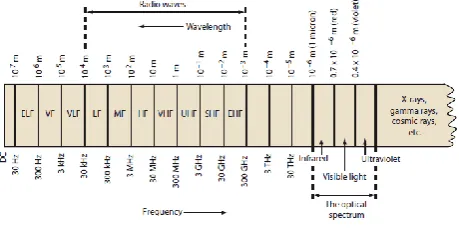
Several carrier frequencies are commonly used in commercially-available RF modules, including those in the industrial, scientific and medical (ISM) radio bands such as 433.92 MHz, 915 MHz, and 2400 MHz These frequencies are used because of national and international regulations governing the used of radio for communication. Short Range Devices may also use frequencies available for unlicensed such as 315 MHz and 868 MHz
RF modules may comply with a defined protocol for RF communications such as ZigBee, Bluetooth low energy, or Wi-Fi, or they may implement a proprietary protocol.
Figure 1 Frequency Spectrum
2- SERIAL PORT
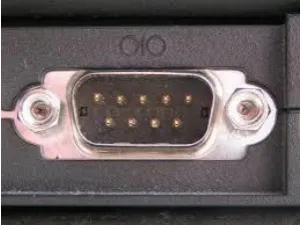
In computing, a serial port is a serial communication interface through which information transfers in or out one bit at a time (in contrast to a parallel port).[1] Throughout most of the history of personal computers, data was transferred through serial ports to devices such as modems, terminals and various peripherals.
RS-232 standard, intended to interface with a modem or with a similar communication device.
Modern computers without serial ports may require serial-to-USB converters to allow compatibility with RS 232 serial devices. Serial ports are still used in applications such as industrial automation systems, scientific instruments, point of sale systems and some industrial and consumer products. Server computers may use a serial port as a control console for diagnostics. Network equipment (such as routers and switches) often use serial console for configuration. Serial ports are still used in these areas as they are simple, cheap and their console functions are highly standardized and widespread. A serial port requires very little supporting software from the host system
Figure 2 Serial Port
3- PROCESSOR (MCU)
The MCU is used to process the data coming from the serial port of the computer. The processor subunit used in this system is the Atmel MCU (ATmega328), we used the Arduino platform that contains the ATmega328 MCU and this platform is the open source platform which is easy to use in terms of software and hardware see Figure bellow. The most important specifications of the MCU are.
Digital I/O 14 Pin
Flash Memory 32 KB (ATmega328) Clock Speed 16 MHz
MCU is programmed through the Arduino programming language which is integrated development environment (IDE). This language based on C / C + + language. We programmed the MCU to control the unit tasks receives data from the serial port of the computer, processing and sending orders to relay shield for the purpose of control of the gate.
Figure 3 Atmel MCU (ATmega328) and the Arduino pin out
4- PROPOSED SYSTEM
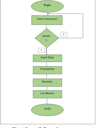
Figure 4 Overall system design
The MCU operation steps and all system as shown in the flowchart in Figure below:
Firstly, we have been connecting the arduino plat form to the pins shows in the figure below.
Figure 5 Pins connection
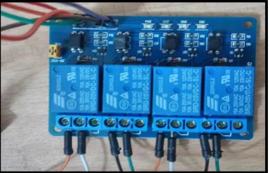
We have been used a relay shield to control the direction of the car and increasing the flexibility in the controlling process. Figure below shows the practical relay shield.
Figure 6 Practical Relay Shield Circuit
Serial Port Connection
Then we have modified our car to receive the signal as shown in the figure below:
Figure 7 Practical Transmission Circuit
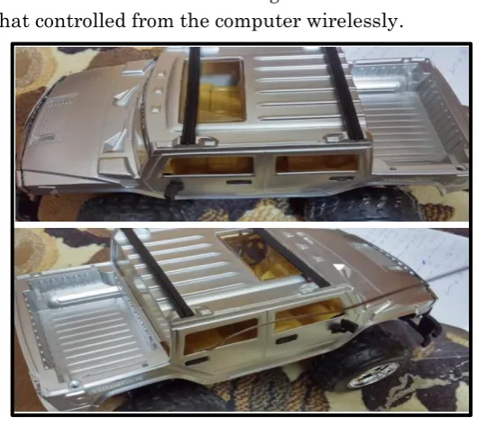
The pictures below were taken during make the test connection of car that controlled from the computer wirelessly.
Figure 8 Practical Car during test process
5- GUI AND SOFTWARE
inside the Arduino and this is used to control and send data to sending circuit and from the serial com in order to send it to the base station for another signal processing . Then we have built and programmed Graphical User Interface (GUI) using visual basic language or (VB.NET).
Figure9 Graphical User Interface (GUI)
REFERENCES
[1] Webopedia (2003-09-03). "What is serial port? - A Word Definition from the Webopedia Computer Dictionary". Webopedia.com.Retrieved 2009-08-07.
[2] D. Heatley, D. Wisely, I. Neild, and P. Cochrane, \Op- tical wireless
The story so far," IEEE Communications Magazine", pp. 72{82, Dec.
1998.
[3] John G. Webster, "Measurement, Instrumentation, and Sensors,Handbook", Text book, CRC Press LLC. , 1999.
[4] "How many Arduinos are "in the wild?" About 300,000". Adafruit Industries. May 15, 2011. Retrieved 2013-05-26.
[5] “Plug pulled on live website seen by millions" by Oliver Burkeman in The Guardian, January 3, 2004.
[7] "Optiboot Bootloader for Arduino and Atmel AVR". Retrieved 2015-10-01.
[8] "Programming Arduino Getting Started with Sketches". McGraw-Hill. Nov 8, 2011. Retrieved 2013-03-28. [9] “Reference guide: Graphics Technical Options and Decisions”,