CFD Analysis of Heat Transfer Rate in Tube in Tube Helical
Coil Heat Exchanger
Mohammed Imran1, Gaurav Tiwari2 and Alwar singh Yadav3
1M.Tech Student/ Mewar University/ Chittorgarh
Rajasthan/ India
2
Dept. of Mechanical Engg., VNIT/ Nagpur Maharashtra/ India
3
Dept. of Mechanical Engg., Mewar University/ Chittorgarh Rajasthan/ India
Abstract
Heat exchangers are the important engineering systems with wide variety of applications including power plants, nuclear reactors, refrigeration and air- conditioning systems, heat recovery systems, chemical processing and food industries. Helical coil configuration is very effective for heat exchangers and chemical reactors because they can accommodate a large heat transfer area in a small space, with high heat transfer coefficients. There is a wide application of coiled heat exchanger in the field of cryogenics and other industrial applications for its enhanced heat transfer characteristics and compact structure. Lots of researches are going on to improve the heat transfer rate of the helical coil heat exchanger. Here, in this work, an analysis has been done for a tube-in-tube helical heat exchanger with constant heat transfer coefficient with turbulent flow. In this paper numerical study of helical coil tube-in-tube heat exchanger is done for different boundary conditions and optimizes condition of heat transfer is found out for different D/d ratio. The turbulent flow model with counter flow heat exchanger is considered for analysis purpose. The effect of D/d ratio on heat transfer rate and pumping power is found out for different boundary conditions
.
Keywords: D/d ratio, Nusselt number, friction factor, LMTD.
1. Introduction
The heat exchanger is a device which is used to transfer heat between two fluids which may be in direct contact or may flow separately in two tubes or channels. We find numerous applications of heat exchangers in day to day life. A heat exchanger may be defined as equipment which transfers the energy from a hot fluid in a cold fluid, with maximum rate and minimum investment and running cost. The rate of transfer of heat depends on the conductivity of the dividing wall and convective heat transfer coefficient between the wall and fluids. For example condensers and evaporators used in refrigerators and air conditioners. In thermal power plant heat exchangers are used in boilers, condensers, air coolers and chilling towers etc. Similarly
the heat exchangers used in automobile industries are in the form of radiators and oil coolers in engines.
The purpose of constructing a heat exchanger is to get an efficient method of heat transfer from one fluid to another, by direct contact or by indirect contact. The heat transfer occurs by three principles: conduction, convection and radiation. In a heat exchanger the heat transfer through radiation is not taken into account as it is negligible in comparison to conduction and convection. [2]
1.1
Type of heat exchangers
1.1.1 According to Heat transfer process:-
Direct Contact Type: Direct contact type Heat exchangers are the heat exchanger in which two immiscible fluids are directly mixed with each other to transfer heat between two fluids.
Transfer Type Heat Exchanger: Transfer type or Recuperater type heat exchanger in which two fluid flows simultaneously through two tubes separated by walls.
Regenerators Type Heat Exchanger: Regenerator type heat exchanger the hot and cold fluid flow alternatively on same surface.
1.1.2 According to Constructional Features:-
Tubular Heat Exchanger: Tubular heat exchangers are placed concentric to each other and two fluids flows in two tubes separated by wall
Shell and Tube type Heat Exchanger: Shell and tube type heat exchanger consists of shell and large number of parallel tubes.
Finned Tube Heat Exchanger: For improving the heat transfer rate fins are provided on the outer surface of the heat exchangers.
1.1.3 According to flow arrangement:-
Counter Flow: Counter flow heat exchanger two fluids flow in opposite direction.
Cross Flow: Cross flow type heat exchanger two fluids flow perpendicular to each other.
1.1.4 Helical coil heat exchanger
Recent developments in design of heat exchangers to full fill the demand of industries has led to the evolution of helical coil heat exchanger as helical coil has many advantages over a straight tube.
The double pipe or the tube in tube type heat exchanger consists of one pipe placed concentrically inside another pipe having a greater diameter. The flow in this configuration can be of two types: parallel flow and counter-flow. It can be arranged in a lot of series and parallel configurations to meet the different heat transfer requirements.
Fig.1 Double pipe helical coil
2. LITERATURE REVIEW
Usman Ur Rehman [5] studied the heat transfer and flow distribution in a shell and tube heat exchanger and compared them with the experimental results. The model showed an average error of around 20% in the heat transfer and the pressure difference.
Vimal Kumar, et.al [6] Nigam conducted an experiment on tube-in-tube heat exchanger and observed that with the increase in operating pressure in the inner tube, the overall heat transfer coefficient increases and the friction factor value in the inner-coiled tube was in agreement with the literature data.
Nawras H. et al. [7] studied on the mechanical and thermal performance of elliptical tubes used for polymer heat exchangers. The mechanical analysis showed that the streamlined shape of the outer tube had an optimal thermal performance.
N. Ghorbani et al. [8] conducted a practical experiment on a vertical helically coiled heat exchanger and found that the coil surface area was the most influential geometrical parameter on the heat transfer coefficient and effect of tube diameter is almost negligible on overall heat transfer coefficient.
Jayakumar et al.[13] had done numerical and experimental work on helical coil heat exchanger considering fluid to fluid heat transfer. They had taken different boundary conditions for example constant heat flux, constant wall temperature and constant heat transfer coefficient.
Jayakumar et al.[14] had done the numerical and experimental analysis to find out the variation of local Nusselt number along the length and circumference of a helical tube. They had changed the pitch circle diameter, tube pitch and pipe diameter and their influence on heat.
Kumar et al. [16] had investigated hydrodynamic and heat transfer characteristic of tube in tube helical heat exchanger at pilot plant scale. They had done the experiment in a counter flow heat exchanger.
Lu et al. [19] had done the experimental and numerical study on the shell-side thermal- hydraulic performance of multilayer spiral wound heat exchangers under different thermal boundary wall conditions.
J. S. Jayakumar et al. [28] studied the constant thermal and transport properties of the heat transfer medium and their effect on the prediction of heat transfer coefficients. Arbitrary boundary conditions were not applicable for the determination of heat transfer for a fluid-to-fluid heat exchanger.
3. PROBLEM FORMULATION
In the literature survey we found that so much work had been done to enhance the heat transfer rate in heat exchanger. But there is no work has been done to optimize the heat transfer rate with respect to power consumption. For simplification in numerical analysis I consider only two turns but in practical problems it may be large number of turns depending on the requirements. The coil diameter (D) was varying from 100mm to 250mm in an interval of 50mm that is 100mm, 150mm, 200mm respectively. As the coil diameter increases the length of the exchanger (L) also increases. The inner tube diameter (d1) was 10mm. the thickness (t) of the tube was taken 0.5mm. The outer tube diameter (d2) was taken 20mm. In my study I fixed the tube diameter (both inner and outer diameter) of the heat exchanger and vary the coil diameter of the tube to see the effect of curvature ratio (d/D) on heat transfer characteristics of a helical coil heat exchanger. The pitch of the coil was taken 40mm that is the total height of the tube was 80mm.
3.1. Boundary conditions
Case 2: Insulated outer wall was taken in the next condition, as given in the Fig. 3.2 (c). At d3=21mm; q=0W/m2.
Table 3.1 Properties of water: [1]
Table 3.2 Properties of copper: [1]
4. RESULTS
4.1 Constant outer wall temperature
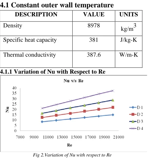
4.1.1 Variation of Nu with Respect to Re
Fig 2.Variation of Nu with respect to Re 4.1.2 Variation of friction factor with respect to Reynolds number for different D/d ratio
Fig.3 variation of friction factor (f) with respect to Re for different D/d ratio
4.1.3 Variation of Nu with Respect to D/d Ratio
Fig.4 variation of Nu with respect to D/d
4.1.4 Variation of friction factor [f] with respect to D/d Ratios
Fig.5 variation of friction factor [f] with respect to D/d Ratio
4.1.5 Variation of LMTD with respect to Re for different D/d ratio
DESCRIPTION VALUE UNITS
Viscosity 0.001003 kg/m-s
Density 998.2
kg/m3
Specific heat capacity 4182 J/kg-K
Thermal conductivity 0.6 W/m-K
DESCRIPTION VALUE UNITS
Density 8978
kg/m3
Specific heat capacity 381 J/kg-K
Fig.6 variation of LMTD with respect to Re for different D/d ratio
4.1.6 Variation of Qnet with respect to Re for different D/d ratio
Fig.7 variation of Qnet with respect to Re for different D/d ratio
4.1.7 Variation of Qnet with respect D/d ratio
Fig.8 variation of Qnet with respect to D/d ratio
5. Conclusions
Numerical simulation has been carried out for tube in tube helical coil heat exchanger subjected to different boundary conditions. Nusselt number, Darcy friction factor, Log means temperature difference pressure drop variation with respect to Reynolds number for different D/d ratio is plotted. In practical application different boundary conditions imposed on the outer wall of exchangers are constant heat flux conditions in power plant boiler, condenser and evaporator etc. insulated outer wall condition in general case of exchanger used in laboratory and educational institutions, and convective heat transfer condition in food, automobile and process industries.
Following are the outcome of above study:-
•
With increase in the Reynolds number, the Nusselt number for the inner tube increase.However, with increases in flow rate
turbulence between the fluid element increases
which will enhance the mixing of the fluid and ultimately the Nusselt number or the heat transfer rate increases.
•
With increases in D/d ratio (inverse of curvature ratio) the Nusselt number will decreases; for a particular value of Reynolds number. Nusselt number has maximum value for D/d=25.•
The outer wall boundary condition does not have any significant effect on the inner Nusselt number, which can be confirmed from the results.•
Friction factor decreases with increase in Reynolds number due to relative roughness of surface, and velocity of flowing fluid.•
Log mean temperature difference increases at a steady rate with increase in Reynolds number.•
As long as the heat transfer is concerned fromthe hot fluid any boundary condition can be assumed for outer wall of external tube because it does not affect significantly the heat transfer rate.
Acknowledgments
I take this opportunity to express my deep sense of gratitude and respect towards my guide Dr. Gaurav Tiwari, Department of Mechanical Engineering, VNIT, Nagpur. I am very much indebted to his for the generosity, expertise and guidance. It is a great pleasure for me to express my gratitude towards those who are involved in the completion of my thesis. I whole-heartedly thank to our Dy. Dean Mr. D.K Sharma, Mr. Amit Kumar, Mr. Dinesh Kumar and Mr. Pradeshi ram for their guidance. I am also indebted to all Staff and others who gave me their valuable time and guidance.
I am also grateful to Co-Guide Mr. Alwar Singh Yadav who gave me his valuable time in completion of my thesis.
References
[1] Styabrata Kanungo, numerical analysis to optimize the heat transfer rate of tube in tube helical coil heat exchangers, NIT Rourkela, (2014).
[2] Danial florez-orrego, experimental and CFD study of singal phase cone helical coiled heat exchanger, ECOS, (2012).
[3] Dr. K.E.Reby roy, numerical analysis of forced convection heat transfer through helical channels, IJEST 4 (2012).
[5] Eiamsa-ard Smith., Promvonge Pongjet., Heat transfer characteristics in a tube fitted with helical screw-tape with/without core-rod inserts, International Communications in Heat and Mass Transfer, vol.-34 (2007) 176–185.
[6] Ferng Y.M., Lin W.C., Chieng C.C., Numerically investigated effects of different Dean number and pitch size on flow and heat transfer characteristics in a helically coil-tube heat exchanger, Applied Thermal Engineering, vol.-36 (2012) 378-385.
[7] Genic Srbislav B., Jacimovic Branislav M., Jaric Marko S., Budimir Nikola J., Dobrnjac Mirko M., Research on the shell-side thermal performances of heat exchangers with helical tube coils, International Journal of Heat and Mass Transfer, vol.-55 (2012) 4295–4300. [8] Ghorbani Nasser., Taherian Hessam., Gorji Mofid., Mirgolbabaei Hessam., An experimental study of thermal performance of shell-and-coil heat exchangers, International Communications in Heat and Mass Transfer, vol.-37 (2010) 775–781.
[9] Huminic Gabriela., Huminic Angel., Heat transfer characteristics in double tube helical heat exchangers using nanofluids, International Journal of Heat and Mass Transfer, vol.-54 (2011)
[10] Jahanmir Gh.S., Farhadi F., Twisted bundle heat
exchangers performance evaluation by CFD,
International Communications in Heat and Mass Transfer, vol.-39 (2012) 1654–1660.
[11] Jamshidi Naghmeh., Farhadi Mousa., Sedighi Kurosh., Ganji Davood Domeiry., Optimization of design parameters for nanofluids flowing inside helical coils, International Communications in Heat and Mass Transfer, vol.-39 (2012) 311–317.
[12] Jamshidi N., Farhadi M., Ganji D.D., Sedighi K., Experimental analysis of heat transfer enhancement in shell and helical tube heat exchangers, Applied Thermal Engineering, vol.-51 (2013) 644-652.
[13] Jayakumar J.S., Mahajani S.M., Mandal J.C., Vijayan P.K., Bhoi Rohidas., Experimental and CFD estimation of heat transfer in helically coiled heat exchangers, International journal of Chemical Engineering Research and Design, Vol.-86 (2008):221-232.
[14] Jayakumar J.S, Mahajani S.M., Mandal J.C., Iyer Kannan N., Vijayan P.K., CFD analysis of single-phase flows inside helically coiled tubes, Computers and Chemical Engineering, vol.- 34 (2010) 430–446.
[15] Kharat Rahul., Bhardwaj Nitin., Jha R.S., Development of heat transfer coefficient correlation for concentric helical coil heat exchanger, International Journal of Thermal Sciences, vol.-48 (2009) 2300–2308. [16] Kumar V., Saini S., Sharma M., Nigam K.D.P., Pressure drop and heat transfer in tube in tube helical
heat exchanger, Chemical Engineering Science, vol.-61 (2006): 4403–4416.
[17] Lee Tzong-Shing ., Wu Wu-Chieh., Chuah Yew-Khoy., Wang Sheng-Kai., An improvement of airflow and heat transfer performance of multi-coil condensers by different coil configurations, International journal of refrigeration, vol.-33 (2010) 1370-1376.
[18] Li Yan., Jiang Xiumin., Huang Xiangyong., Jia Jigang., Tong Jianhui., Optimization of high- pressure shell-and-tube heat exchanger for syngas cooling in an IGCC, International Journal of Heat and Mass Transfer, vol.-53 (2010) 4543–4551.
[19] Lu Xing., Du Xueping., Zeng Min., Zhang Sen.,
Wang Qiuwang., Shell-side thermal-hydraulic
performances of multilayer spiral-wound heat
exchangers under different wall thermal boundary conditions, Applied Thermal Engineering, Article in press(2014) 1-12.