ISSN (Print) : 2320 – 3765 ISSN (Online): 2278 – 8875
I
nternational
J
ournal of
A
dvanced
R
esearch in
E
lectrical,
E
lectronics and
I
nstrumentation
E
ngineering
(An ISO 3297: 2007 Certified Organization)
Vol. 5, Issue 5, May 2016
Design and Development of High Efficiency,
Low Cost Three Phase Induction Motor
Controller for Solar Water Pump
Dr. S. N. Patil1, Swati A. Killedar2
Associate Professor, Dept. of Electrical Engineering, TSSM’S BSCOER, Narhe, Pune, India1
PG Student [Power System], Dept. of Electrical Engineering, TSSM’S BSCOER, Narhe, Pune, India2
ABSTRACT: In this paper a three phase induction motor controller for a photovoltaic powered water pump without
the use of chemical storage element is presented. The use of a three-phase induction motor is a better solution to the dc motor water pumping system. This system is use to achieve a more efficient, reliable, maintenance-free, and cheaper solution than that use dc motors or low-voltage synchronous motors. The developed system is based on a Single-Ended Primary Inductor converter (SEPIC) and a full-bridge three-phase voltage source inverter (VSI).Maximum Power Point Tracking (MPPT) algorithm has been developed and implemented to maximize the use of solar power generated at any given instant. By using MATLAB/ Simulink model is implemented. The system is expected to have a high lifetime due to the inexistence of storage element. As a result, the system is a economical solution to deliver water to household, industrial and agricultural activities which require water supply.
KEYWORDS: Photovoltaic (PV) power systems, Single-Ended Primary Inductor Converter (SEPIC), Voltage Source
Inverter (VSI), Maximum Power Point Tracking (MPPT).
I.INTRODUCTION
The increased use of water pumping and increasing cost of conventional energy sources promote the use of solar energy as an energy source for the water pumping especially in isolated sites. Photovoltaic powered systems are becoming increasingly popular due to (i) the absence of the power line near the water pumping sites in remote areas, frequent shortage of electrical power and hence failure to meet the ever rising load demand (ii) environmental degradation caused by the fossil fuel based power plants (iii) ever rising cost of fossil fuel based electricity and (iv) fast declining cost of PV electricity[1].The majority of the available commercial converters are based on an intermediate storage system, performed with the use of lead–acid batteries, and dc motors to drive the water pump[2]. The batteries used to operate the motor at its rated power even though low solar radiation condition. Generally, the batteries used in this type of system have a low life span, only two years on average, which is extremely low compared to the useful life of 20 years of a PV module [2]. Also, they make the installation and maintenance cost of such systems considerably high [3].The majority of systems use low-voltage dc motors, thus avoiding a boost stage between the PV module and the motor. But, dc motors have lower efficiency and higher maintenance cost compared to induction motors and are no suitable for applications in isolated areas [3].
ISSN (Print) : 2320 – 3765 ISSN (Online): 2278 – 8875
I
nternational
J
ournal of
A
dvanced
R
esearch in
E
lectrical,
E
lectronics and
I
nstrumentation
E
ngineering
(An ISO 3297: 2007 Certified Organization)
Vol. 5, Issue 5, May 2016
for proposing the DC-DC Converters, hence SEPIC is better [7]. PV pumping systems without battery can provide a cost effective use of solar energy. Nowadays, due to development of IM drive systems it is possible to use a more robust and less expensive motor for photovoltaic pumping application [9] [10]. Following are the features of current topology: high efficiency due to the low energy available; low cost; no specific training needed to operate the system; minimum amount of maintenance possible and high life span comparable to the usable life of 20 years of a PV panel.
The aim of this paper is to show how to achieve an effective solar water pumping system without use of batteries. This system consists of PV array, MPPT, SEPIC, Inverter, Induction motor and pumping system.
II.BLOCK DIAGRAM
Fig. 1 Block diagram of the proposed system.
Fig.1. shows the simplified block diagram of proposed PV water pumping system. The energy produced by the PV panel is fed to the motor through a converter with two power stages: a dc-dc single ended primary inductor converter (SEPIC) and dc-ac phase inverter. DC-DC converter is used to boost the voltage of the panels and a dc/ac three-phase inverter to convert the dc voltage to three-three-phase ac voltage. The inverter is based on a classic topology and uses a sinusoidal pulse width modulation (PWM) The use of this PWM strategy is to improve the output voltage level as compared to sinusoidal PWM modulation. MPPT algorithm is implemented through dc-dc converter. Pulse width modulation signal is given to three phase inverter and it continuously check speed of induction motor, and generate required signal to drive the water pump.
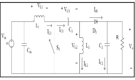
III.DC-DC CONVERTER
Fig. 2 Diagram for a basic SEPIC converter
ISSN (Print) : 2320 – 3765 ISSN (Online): 2278 – 8875
I
nternational
J
ournal of
A
dvanced
R
esearch in
E
lectrical,
E
lectronics and
I
nstrumentation
E
ngineering
(An ISO 3297: 2007 Certified Organization)
Vol. 5, Issue 5, May 2016
low/the switch is off, the inductors output through the diode to the load and the capacitors are charged. The greater the percentage of time (duty cycle) the pulse is low, the greater the output will be. This is because the longer the inductors charge, the greater their voltage will be. The converter will fail if capacitors will not be charge because of pulse being too long. This dc-dc converter allowing the electrical voltage at its output to be greater than, less than, or equal to that at its input; the output of the SEPIC is controlled by the duty cycle of the control switch. Step up or step down the voltage of SEPIC depends primarily on the duty cycle and the parasitic elements in the circuit.
The output of an ideal SEPIC converter [8] is given by (1)
= ( ⁄ −1 1) (1)
However, this does not account for losses due to parasitic elements such as the diode drop ( ). Then above equation becomes
+ = ( ⁄ −1 1) (2)
This becomes
= (3)
In theory, the larger the inductors are the better the circuit will operate and reduce the ripple. However, larger inductors are more expensive and have a larger internal resistance. This greater internal resistance will make the converter less efficient. Creating the best converter requires choosing inductors that are just large enough to keep the voltage and current ripple at an acceptable amount.
=
∆ (4)
IV.MPPT CONTROL
Perturb and Observe MPPT algorithm is used to achieve maximum power point. Maximum power point tracker uses different control circuits to search for this point and allow the converter circuit to extract the maximum power available from cell. The operating point on the characteristics of the PV module primarily depends on the impedance matching of the PV module with respect to the connected load. A dc–dc converter between the PV module and the load acts as an interface to operate at MPP by changing the duty cycle of the converter generated by the MPPT controller. Using input and output voltage relation for SEPIC ( ie. = ( ⁄ −1 1) ), efficiency of the converter can be expressed by (5)
= =
/ = = (5)
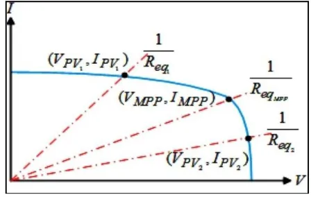
Where and are the PV voltage and current, respectively. The equivalent input resistance ( ) of the converter as seen by the PV module can be obtained from (5) as follows:
= (6)
From (6), it can be noticed that, by changing the duty cycle, the operating point can be changed as changes, as shown in Fig. 3, and the MPPT controller should change the duty cycle in order to track the peak power.
ISSN (Print) : 2320 – 3765 ISSN (Online): 2278 – 8875
I
nternational
J
ournal of
A
dvanced
R
esearch in
E
lectrical,
E
lectronics and
I
nstrumentation
E
ngineering
(An ISO 3297: 2007 Certified Organization)
Vol. 5, Issue 5, May 2016
Fig. 4 P–Vcharacteristics to achieve maximum power point
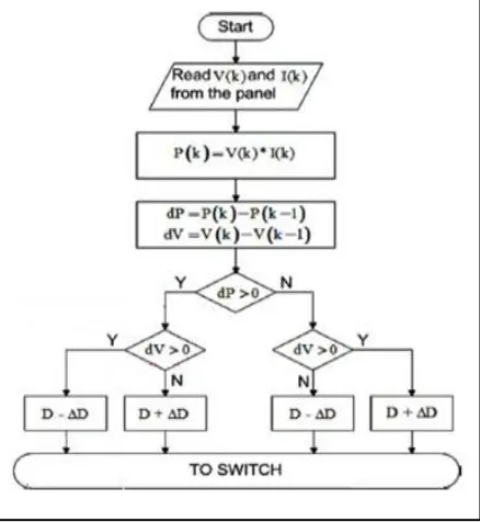
In the current method the controller adjusts the voltage from array and measures power, if the power increases, further adjustments in the direction are tried until there is no increase of power. This is called P and O method. It is the most commonly used MPPT method Because of ease of implementation. PV modules output power curve as a function of voltage (P-V curve), at the constant irradiance and the constant module temperature, assuming the PV module is operating at a point which is away from the MPP. From the P–Vcharacteristics shown in fig.4, it can be visualized that the operating voltage of the PV module is perturbed by a small increment, and the resulting change of power, P is observed. If the P is positive, then the operating point has moved toward the MPP. Thus, further voltage adjustments in the same direction should move the operating point toward the MPP. Direction of perturbation should be reversed if the P is negative as the operating point has moved away from the MPP. The duty cycle and the PV voltage ( ) are inversely proportional to each other, i.e., an increase in duty cycle causes the ( ) to decrease and vice versa. The flow chart of P and O algorithm is shown in fig. 5.
ISSN (Print) : 2320 – 3765 ISSN (Online): 2278 – 8875
I
nternational
J
ournal of
A
dvanced
R
esearch in
E
lectrical,
E
lectronics and
I
nstrumentation
E
ngineering
(An ISO 3297: 2007 Certified Organization)
Vol. 5, Issue 5, May 2016
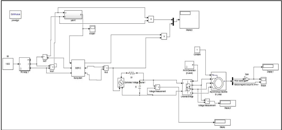
V. SIMULINK DESIGNS FOR PV WATER PUMPING SYSTEM
The most important decision in this process is the choosing of the solar cells. Silicon is the major manufactured materials exist for solar cells. Silicon was the material of the first solar cells and nowadays is mostly used in terrestrial settings due to its low production cost and low efficiency. Terrestrial applications generally value cost over surface area consumed so silicon is a great fit. These cells generally range from 12%- 18% efficient and come in two crystal types, mono crystalline and polycrystalline [1].The fig.6.represents the circuit used in simulink model. The fundamental magnitude of the output inverter can be controlled to be constant by exercising control within the inverter itself that is external circuit is not required. The most efficient method of doing this is by Pulse Width Modulation (PWM) control used within inverter. In this scheme the inverter is fed by a fixed controlled ac voltage.
Fig. 6 Simulink model for PV water pumping system.
VI. RESULT AND DISCUSSION
Table I shows the efficiency of converter after implementation of MPPT algorithm with different solar irradiation. Due to implementation of MPPT algorithm efficiency of converter is increases hence efficiency of overall system is considerably increases.
Table I. Efficiency of converter after implementation of MPPT algorithm Irradiance
(w/m2)
Input Power (watt)
Output Power (watt)
Efficiency (%)
1200 1558 1472 94.48
1000 1520 1432 94.21
800 1472 1390 94.42
600 1409 1330 94.39
400 1318 1241 94.15
200 1139 1060 93.06
ISSN (Print) : 2320 – 3765 ISSN (Online): 2278 – 8875
I
nternational
J
ournal of
A
dvanced
R
esearch in
E
lectrical,
E
lectronics and
I
nstrumentation
E
ngineering
(An ISO 3297: 2007 Certified Organization)
Vol. 5, Issue 5, May 2016
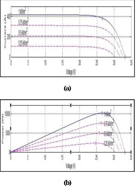
operating point such that panel delivers maximum power to load. There are different optimum points for different irradiance level.
(a)
(b)
Fig. 7 Characteristics of PV panel a) I-V Characteristics with different irradiance b) P-V Characteristics with different irradiance
Fig. 8 shows the input power and output power of SEPIC after implementation of MPPT algorithm. Power from solar panel given to the SEPIC is fluctuated because of changes in environmental conditions and output power of converter first slowly increases and then it becomes stable. Due to this Efficiency of converter is increase.
ISSN (Print) : 2320 – 3765 ISSN (Online): 2278 – 8875
I
nternational
J
ournal of
A
dvanced
R
esearch in
E
lectrical,
E
lectronics and
I
nstrumentation
E
ngineering
(An ISO 3297: 2007 Certified Organization)
Vol. 5, Issue 5, May 2016
Fig. 9 Output waveform of MPPT
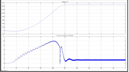
Fig.9 shows the pulses generated from MPPT ie, output waveform of maximum power point tracker. Fig.10 represents simulation results of speed and torque of three phase induction motor used for water pumping by means of PV energy.
Fig. 10 Speed and Torque of three phase induction motor
VII.CONCLUSION
This paper presents the simulation of PV powered induction motor water pumping system without the use of storage elements. The model can be used to relate input quantities like solar array voltage, current to outputs like speed, torque. The simulation of integrated system is presented the results can be used to select the ratings of the various components.
This paper presents the block diagram of system, control algorithm, and design. The simulation results suggest that the proposed solution could be a viable option for PV water pumping system. And it is a viable solution having low cost, high efficiency, and robustness.
REFERENCES
[1] P Sadasivam, MKumaravel, Krishna Vasudevan and Ashok Jhunjhunwala, “Analysis of Subsystems Behaviour and Performance Evaluation of Solar Photovoltaic Powered Water Pumping System”, Indian Institute of Technology Madras, Chennai, Tamilnadu, 600036, India 2014. [2] Author H. Harsono, “Photovoltaic water pump system”, Ph.D. dissertation, Dept. Intell. Mech. Syst. Eng., Faculty Kochi Univ. Technol.,
Kochi, Japan, Aug. 2003
[3] M. A. Vitorino and M. B. R. Correa, “High performance photovoltaic pumping system using induction motor”, in Proc. Brazilian Power Electron. Conf., 2009, pp. 797804.
[4] Mohammed A. Elgendy, Bashar Zahawi and David J. Atkinson, “Assessment of Perturb and Observe MPPT Algorithm Implementation Techniques for PV Pumping Applications”, IEEE Transactions on sustainable Energy, Vol. 3, No. 1, January 2012.
ISSN (Print) : 2320 – 3765 ISSN (Online): 2278 – 8875
I
nternational
J
ournal of
A
dvanced
R
esearch in
E
lectrical,
E
lectronics and
I
nstrumentation
E
ngineering
(An ISO 3297: 2007 Certified Organization)
Vol. 5, Issue 5, May 2016
[6] R. Faranda and S. Leva, “Energy comparison of MPPT techniques for PV systems”, WSEAS Trans. Power Syst., vol. 3, no. 6, pp. 446455, Jun. 2008.
[7] Mummadi Veerachary, Senior Member, IEEE Indian Institute of Technology Delhi “PV Sources with Coupled Inductor SEPIC Converter” [8] Muralidhar Killi and Susovon Samanta, “Modified Perturb and Observe MPPT Algorithm for Drift Avoidance in Photovoltaic Systems”, IEEE
Transactions On Industrial Electronics, Vol. 62, No. 9, September 2015.
[9] S.G. Malla, C.N. Bhende and S. Mishra “Photovoltaic based Water Pumping System”