ISSN (Print) : 2320 – 3765 ISSN (Online): 2278 – 8875
I
nternational
J
ournal of
A
dvanced
R
esearch in
E
lectrical,
E
lectronics and
I
nstrumentation
E
ngineering
(An ISO 3297: 2007 Certified Organization)
Vol. 5, Issue 4, April 2016
Study of SIDO Implementation Using Flyback
Converter for Power Factor Improvement
with the Help of ANN Controller
Damini Tandan1, Amit Goswami2
M.Tech Student [EDPSE], Dept. of EEE, DIMAT College, Raipur, Chhattisgarh, India1
Assistant Professor, Dept. of EEE, DIMAT College, Raipur, Chhattisgarh, India2
ABSTRACT
:
In this design, we purpose to design a single inductor dual output implementation using flay back converter for power factor correction. By which the regulated output will obtain through each output, here we study between the PID controller and the artificial neural network which is better to improve the power factor. Compared with two stages multiple outputs, SIDO PFC using fly back converter with the ANN controller has some benefits that provide the reduced undershooting, overshooting, harmonics and oscillation (i.e. total harmonic distortion (THD). Main purpose to design this circuit improving the power factor from 0.933 to 0.994 is can be assume in our study because ANN controller provides less settling time, that also small size, light weight, cost saving. This project is shows that at the same value the ANN controller is more accurate. Here also AC input providing and dual DC output, there is no need of converter. We can use motor instead of resistive load to conclude that our purposed converter is also suitable to DC drive or DC motor. The MATLAB Simulation is using for designing purpose.KEYWORDS: Total harmonic distortion, Power factor correction, Artificial Neural Network.
I. INTRODUCTION
ISSN (Print) : 2320 – 3765 ISSN (Online): 2278 – 8875
I
nternational
J
ournal of
A
dvanced
R
esearch in
E
lectrical,
E
lectronics and
I
nstrumentation
E
ngineering
(An ISO 3297: 2007 Certified Organization)
Vol. 5, Issue 4, April 2016
Fig.1 Dual or multiple output ac/dc power converters with high power factor.
We are using the same circuit of SIDO buck boost power factor correction converter with PDI Controller. Now there is a two method to calculate the values of voltage, current power and THD. First through the specific conventional equations and next is the calculation through the pulses. Here we use the second method and our methodology based on the pulse width modulation. We choose this method because we using the artificial neural network and that pulse method is beneficial for it. Artificial neural network (ANN) has the capacity to learn system through nonlinear system through nonlinear Mappings. In [5] and [6], the PWM converter have been design in a single non-linear system using a power balance concept between the input and output sides. Advantages of neural network are controller is robust to parameter drifting and changes of operating point, quick switching response, simpler structure and better output waveform. There are many PWM techniques for AC/DC converter like UPWM, BPWM, HPWM and hybrid PWM. However, these PWM have higher switching stress but in proposed PWM, only one switch is active during one switching period. By using neural network switches operated at very high frequency in ac voltage waveform harmonic spectrum allowing the harmonics to be filter out.[4] The proposed system has the following advantage such as lower THD, minimize settling time, minimize overshoot, undershoot and fast switching operation. This scheme provides fast output voltage response and improves input current shaping.
II. SYSTEMDISCRIPTION
Here, we use a bridge rectifier to produce an output voltage or current which is purely dc or has some DC component. Full wave rectifier (bridge) some fundamental advantages over their half wave counterpart. The average output voltage is higher than for half wave, the output of the full wave rectifier has much less ripple than that of the half wave rectifier producing a smoother output wave form.
The output formed from bridge rectifier has a full wave DC which may consist of harmonics/noise. The input filter consist of L and C, 3switches Q1,Q2,Q3 and their corresponding sense resistor R,R1,R2. Fly back converter a time multiplexing inductor L1 and two output filter capacitor C1, C2. The PID controller loop of SIDO buck boost PFC converter with the two output content
current.
R1 series connected with Q1, Q2,Q3 respectively these common connected points is set single ground. In sub converter A the DC load current Idca is compared with the reference valuethe error or difference between these goes to the PID controller which works as a current controller. Hence controlling current and produce the voltage which get saturated through the saturation block. The saturated DC voltage is compared with a carriers (triangular waveforms) signals in the relational operator, for producing required pulse A and also this pulse is used to provide gate signals to switch Q1.
ISSN (Print) : 2320 – 3765 ISSN (Online): 2278 – 8875
I
nternational
J
ournal of
A
dvanced
R
esearch in
E
lectrical,
E
lectronics and
I
nstrumentation
E
ngineering
(An ISO 3297: 2007 Certified Organization)
Vol. 5, Issue 4, April 2016
the power factor correction regulator circuit that improves the power quality. The input values of parameter shown in the table .With the same parameters and the same above working applying to the same circuit design with the Artificial neural network.
III. OPERATION PRINCIPLE OF THE PROPOSED SIMPLIFIED PWM STRATEGY WITH THE ANN CONTROLLER
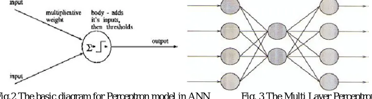
The proposed project presents a simplified PWM strategy with the ANN having advantage of good current shaping and dc voltage regulation. Good voltage regulation provides high quality output voltage for dc loads and current shaping provides minimum harmonic pollution. In ANN, The simple neuron model is made from studies of the human brain neurons. A neuron in the brain receives its chemical input from other neurons through its dendrites. If the input exceeds a certain threshold, the neuron fires its own impulse on to the neurons it is connected to by its axon. The simple perceptron models this behavior in the following way. First the perceptron receives several input values (x0 - xn). The connection for each of the inputs has a weight (w0- wn) in the range 0-1. The Threshold Unit then sums the inputs, and if the sum exceeds the threshold value, a signal is sent to output. Otherwise no signal is sent.[3] Fig.1 shows.
The MLP
is divided into three layers: the input layer, the hidden layer and the output layer, where each layer in this order gives the input to the next. The extra layers gives the structure needed to
recognize non-linearly separable classes.
Fig.2 The basic diagram for Perceptron model in ANN Fig. 3 The Multi Layer Perceptron
Algorithm
The threshold function of the units is modified to be a function that is continuous derivative, the Sigmoid function. The use of the Sigmoid function gives the
S(t) = ………..(i)
Extra information necessary for the network to implement the back-propagation training algorithm. Back-propagation works by finding the squared error (the Error function) of the entire network, and then calculating the error term for
TABLE –I
Circuit Parameter of SIDO buck boost PFC converter
Variable
Vin Input voltage 100-240v ac
VA Reference voltage for sub converter A 60V
VB Reference voltage for sub converter B 75V
Cf Filter capacitor 100nf
Rf filter resistance 120k ohms
Lf Input filter inductor 1mH
Q1 Power MOSFET 7N65
Q2,Q3 Multiplexing MOSFET IRFR13N15D
F Frequency 50Hz
Ra,Rb Related load resistor of output A,B 300 ohms
ISSN (Print) : 2320 – 3765 ISSN (Online): 2278 – 8875
I
nternational
J
ournal of
A
dvanced
R
esearch in
E
lectrical,
E
lectronics and
I
nstrumentation
E
ngineering
(An ISO 3297: 2007 Certified Organization)
Vol. 5, Issue 4, April 2016
each of the output and hidden units by using the output from the previous neuron layer. The weights of the entire network are then adjusted with dependence on the error term and the given learning rate. Training continues on the training set until the error function reaches a certain minimum. If the minimum is set too high, the network might not be able to correctly classify a pattern. But if the minimum is set too low, the network will have difficulties in classifying noisy patterns.[7]
A sigmoid function is a mathematical function having an "S" shape (sigmoid curve).
a sigmoid function is real-valued and differentiable, having either a non-negative or non-positive first derivativewhich is bell shaped. There are also a pair of horizontal asymptotes as t =±∞. The differential equation
( ) = 1 ( ) 2− ( ) , ………(ii)
with the inclusion of a boundary condition providing a third degree of freedom, C3, provides a class of functions of this type.
The logistic function has this further, important property, that its derivative can be expressed by the function itself, S’ (t) = S(t)(1-S(t)). ………(iii)
IV. MODELING SIDO IMPLEMENTATION USING BUCK BOOST CONVERTER USING PID CONTROL TECHNIQUE AND ANN CONTROLLER
Fig.4 SIDO implementation using buck boost converter using PID control technique.
AC Input
Discrete, Ts = 1e-06 s.
ISSN (Print) : 2320 – 3765 ISSN (Online): 2278 – 8875
I
nternational
J
ournal of
A
dvanced
R
esearch in
E
lectrical,
E
lectronics and
I
nstrumentation
E
ngineering
(An ISO 3297: 2007 Certified Organization)
Vol. 5, Issue 4, April 2016
Fig.5 Input voltage V- current I waveforms.
Fig.5 shows the input value of the system the system there is the voltage shown in upper half i.e. 230v and the next half is shown the input current value i.e. 0.6A.
Fig.6 Power factor waveform by using PID controller
ISSN (Print) : 2320 – 3765 ISSN (Online): 2278 – 8875
I
nternational
J
ournal of
A
dvanced
R
esearch in
E
lectrical,
E
lectronics and
I
nstrumentation
E
ngineering
(An ISO 3297: 2007 Certified Organization)
Vol. 5, Issue 4, April 2016
Fig.7 Output waveform of V-I for sub converter A
Fig.8 Output waveform of V-I for sub converter B
ISSN (Print) : 2320 – 3765 ISSN (Online): 2278 – 8875
I
nternational
J
ournal of
A
dvanced
R
esearch in
E
lectrical,
E
lectronics and
I
nstrumentation
E
ngineering
(An ISO 3297: 2007 Certified Organization)
Vol. 5, Issue 4, April 2016
Fig.9 FFT analysis for existing Single-Inductor Dual-Output Buck-Boost Power Factor Correction Converter using PID controller for THD.
The above fig. shows the THD through the PID controller that is 16.63%. The THD will reduce through the ANN in proposed circuit show in fig.10.
V.THE PROPOSED SYSTEM MODELING
ISSN (Print) : 2320 – 3765 ISSN (Online): 2278 – 8875
I
nternational
J
ournal of
A
dvanced
R
esearch in
E
lectrical,
E
lectronics and
I
nstrumentation
E
ngineering
(An ISO 3297: 2007 Certified Organization)
Vol. 5, Issue 4, April 2016
VI. ADVANTAGES OF THE PROPOSED SYSTEM
After using neural network as a controller in our proposed system of our project, they are following merits in the
system:- Maximum undershoot and overshoot can be minimized.
Settling time can be reduced.
Power Factor Correction can be increased.
Harmonics can be reduced.
In future, the work can be proposed by using Neuro-Fuzzy Controller, which has to be implemented through hardware as to calculate the losses.
VII. CONCLUSION
This paper presents a simplified PWM strategy using feed forward control scheme with neural network. In this paper, existing and proposed model is compared based on THD, undershoot, overshoot and system efficiency. In proposed system with PID controller is replaced by neural network. Figure shows that existing system with PID controller has higher THD, and in next figure it is shown that, proposed system with neural network has less THD. That means our proposed system has better efficiency the main purpose is the system design the power factor improve through the ANN method here the .968 is the power factor through the PID controller that improve by the ANN i.e. 0.99.That proposed model is shows that for same input values the ANN control method is more beneficial.
ACKNOWLEDGMENT
The author would like to thank Prof. Amit Goswami of DIMAT Raipur in India for his Kind assistance.
REFERENCES
[1] Single-Inductor Dual-Output Buck-Boost Power Factor Correction Converter
Xueshan Liu, Jianping Xu, Member, IEEE, Zhangyong Chen and Nan Wang( IEEE TRANSACTIONS ON INDUSTRIAL ELECTRONICS) [2]. A New Standby Structure Using Multi-Output Full-Bridge Converter Integrating Fly back Converter
Jae-Kuk Kim, Student Member, IEEE, Seong-Wook Choi, Student Member, IEEE, Chong-Eun Kim, Member, IEEE, and Gun-Woo Moon, Member, IEEE
[3] Neural Networks – algorithms and applications Neural Networks – algorithms and applications By Fiona Nielsen 4i12/12-2001
[4] Study of Bidirectional AC/DC Converter with Feed forward Scheme using Neural Network Control in Micro grid System Kanchan Bala Rai1 Neelesh Kumar2 Department of Electrical and Electronics Engineering
Disha Institute of Management and Technology, Raipur, Chhattisgarh, India (IJSRD - International Journal for Scientific Research & Development| Vol. 4, Issue 01, 2016 | ISSN (online): 2321-0613
[5] H.Sugimoto, S.Moritoma, and M.Yano, “A high performance control method of a voltage type PWM converter”, in conference IEEE PESC 88, April 1988, pp.360-368.