A Low Power Control System for Wireless Body Area
Sensor Networks using Adaptive Fuzzy Logic
Mahankali Mahesh Varma,Pg Student
Mr. K. Suresh, Assistant Professor
Dept Of Ece
Malla Reddy College of Engineering & Technology,Secunderabad
Abstract: Wireless body sensor networks (WBSNs) for medical applications, such as vital signal
monitoring and the diagnose assistant has received tremendous attention in recent years.
Wireless sensing system tends to focus on low power consumption. Firstly, an adaptive fuzzy
controller is designed and a statistical analysis of the performance of the system is conducted. An
adaptive-resolution control system based on a fuzzy control technique is designed for wireless
body sensor networks in order to develop a high quality and low power system. The concept of
the adaptive resolution control technique is to produce the control signals by selecting different
clock frequencies with fuzzy decision technique. The results show that this work can improve the
quality of ECG signals in abnormal region and also reduce transmission power for wireless body
sensor networks. Results prove that adaptive fuzzy logic can adapt rapidly and successfully to
the changing dynamic situation with which it is presented.
INDEX TERMS Adaptive, fuzzy control, healthcare monitoring, power-efficient, wireless body
sensor network.
I. INTRODUCTION In recent years,
homecare services [1], [2] have been widely
discussed and investigated in the area of
academic and commercial research. The
advancement of wireless transmission
techniques provides simplicity and comfort
in health monitoring, specifically in
identifying the health conditions of each
individual. One of the famous topics in this
(WBSN) [3], [4]. In practical applications, it
is efficient to apply a wireless body sensor
network in a hospital to monitor the vital
signs of patients and build up a long-term
wireless sensing system in a house to take
care of chronically diseased patients. A
WBSN provides an efficient instrumentation
and measurement to monitor physiological
parameters without affecting the normal life
of patients. There are various kinds of bodily
signals designed into WBSNs [5], [6], such
as body temperature [7], heart rate, blood
pressure [8], pH value [9], ECG, etc. In
order to be compatible with the various
bodily signals in the WBSN, a multi-sensor
microcontroller unit (MCU) with an
asynchronous interface was proposed in [10]
and [11]. Although the cost and power have
been reduced by the multi-sensor design, the
power consumption still limits the lifetime
usage of the WBSN. Similar to other
wireless mobile applications, an
ultra-low-power design is necessary for long-term
monitoring of physiological variables (vital
signs) [12], [13]. In the previous work [14],
an adaptive low-power technique was
proposed in which the power consumption
of the WBSN systems has been successfully
reduced. Although the most redundant
communication power was saved by the
adaptive low-power technique, the reduction
of transmission power is still limited by the
data rates of the transmission. Data rates of
the transmission are limited a specific data
rate because the various body signals are
captured by the ADC with a fixed sampling
rate. Although higher frequency of the
sampling rate implicates more accurate
detection, it consumes more power for
transmitting huge amount of data. It is
difficult to choose between the power
consumption and resolution because higher
resolutions of the sensing systems will
consume more energy for transmission. has
benefits of long-term usage and high
resolution. In the previous work [15], a
variable resolution control system had been
proposed for WBSN system. Yazicioglu et
al. [16] presented an adaptive sampling
ADC for ECG compression. Kim et al. [17],
[18] proposed a mixed-signal ECG
processing platform with adaptive sampling
by an analog signal processor (ASP). These
adaptive resolution techniques were
successfully developed to promote the
quality of body signals and reduce the power
consumption of the sensing system.
However, the flexibility and the reduction of
the power consumption were not efficient
control system based on a fuzzy control
technique [19]–[21] has been proposed to
develop a flexible, power-efficient, and
high-resolution WBSN system. It provides
an efficient methodology to develop a
long-term usage and high-resolution wireless
sensing system for healthcare monitoring
applications. This paper is organized as
follows: Section II introduces the principles
of the adaptive fuzzy control system.
Section III describes the architecture of a
wireless body sensor node with the proposed
adaptive fuzzy resolution control design.
Section IV shows the simulation results and
chip designs. Finally, in Section V, the
conclusions are presented.
A. ADAPTIVE FUZZY RESOLUTION
CONTROL TECHNIQUE The concept of
the adaptive resolution control technique is
to control the resolution of the signals by
selecting different clock frequencies and
then using these frequencies as the sampling
clock of the ADC. Initially, the users can set
the conditions, and then the controller will
produce control signals automatically to
select the most suitable frequency of the
clock and use it as the sampling clock of the
ADC. For example, the adaptive fuzzy
controller will select a high-frequency clock
(HCLK) as the sampling clock of the ADC
when the specific body signal demands a
high-quality resolution. Fig. 1 shows two
window-conditions of the proposed adaptive
resolution control technique. It includes a
high-level condition-window and a
low-level condition-window. The high-low-level
condition window comprises of high-level
plus and level minus, wherein the
level plus is the upper bound of the
high-level condition window while the high-high-level
minus is the lower bound of the high-level
condition window. The two
window-conditions help users to set the resolution
conditions for some specific applications.
For example, the users or doctors can set the
values of high-level plus and low-level
minus into the proposed system when the
values of the detected signals more than the
value of FIGURE 1. Two
window-conditions of the proposed adaptive
resolution control. high-level plus or less
than the value of low-level minus are
important or dangerous. The sampling clock
of the ADC can be adaptively selected from
high-frequency clock (HCLK),
medium-frequency clock (MCLK) or low-medium-frequency
clock (LCLK) according to outputs of the
fuzzy sets. Fig. 2 illustrates an example of
the adaptive resolution control technique, in
integrated by three different sampling clocks
(HCLK, MCLK, and LCLK). Initially, the
user can set the Adaptive_CLK to LCLK.
Later on, when the result of fuzzy logic
control is High, the Adaptive_CLK is set to
HCLK. Then, when the result of fuzzy logic
control is changed to Medium, the
Adaptive_CLK will be changed from HLCK
to MCLK. Finally, the Adaptive_CLK is set
to LCLK since result of fuzzy logic control
is Low. By this adaptive fuzzy control
technique, the resolution of the biomedical
signals can be set to the most suitable
condition by selecting the sampling clock of
the ADC. B. FUZZY CONTROL
TECHNIQUE Fuzzy logic is widely used in
control, prediction [19], and detection [20],
[21] of non-linear systems. It provides an
efficient methodology to handle the concept
of partial truth. In order to improve the
performance of the adaptive resolution
control, a fuzzy logic control based on if. .
.then. . . rules was developed for adaptive
resolution control, in which each rule
illustrates the relation between input and
output fuzzy sets. It was used to select
different frequency of clocks as the
sampling clock of the ADC. The rules,
functions, and parameters of the fuzzy logic
control can be set according to the
applications. For example, the absolute
values, slope, frequency, variation,
transform, etc. of body signals can be
selected as parameters for fuzzy logic
control. In addition, the fuzzy rule can be
obtained by the relation of the selected
parameters and simulated results.
FIGURE 1. Two window-conditions of the
FIGURE 2. Samples schedule in HCLK,
MCLK, LCLK, and Adaptive CLK.
concept of the proposed adaptive fuzzy
control system. Users can use different
parameters and fuzzy rules to produce the
best fuzzy logic control models for their
applications through the proposed adaptive
fuzzy control system. The applications of
the proposed system are not limited in this
ECG example. In this example, the inputs
are the absolute value of f (n) and slope
value of g(n), as presented in Eq. (1) and (2),
were selected as fuzzy parameters. Fig. 3
shows the relations between the ECG signals
and fuzzy logic parameters. The parameters
of the fuzzy logic control in this example are
defined as follow: f (n) = abs(P(n)) (1) g(n)
= abs(P(n) - P(n-1)) (2) where P(n) is
amplitude of ECG signal in this example.
FIGURE 3. Relations between the value of
ECG signal P(n), and the fuzzy logic
parameters g and f.
Table 1 was designed for adjustment the
frequency of the sampling clock of the
ADC. Some of important considerations that
have been taken into account for
determining the rules are as follows. 1) The
sampling clock of the ADC is selected as
HCLK when the variations or values of the
ECG signal are out of the condition
windows as shown in Fig. 1. For example, if
g is Very Low and f is Very Low then the
sampling clock is selected as HCLK or if g
is Very High and f is Very High then the
sampling clock is HCLK. 2) The sampling
clock of the ADC is selected as MCLK
when the variations and values of the ECG
signal are both within TABLE 1. Fuzzy
sampling clock. the condition windows as
shown in Fig. 1. For example, if g is
Medium and f is Medium then the sampling
clock is MCLK. 3) The sampling clock of
the ADC is selected as LCLK when the
variations and values of the ECG signal are
located in the interval between the
High-Level and Low-High-Level condition windows as
shown in Fig. 1. For example, if g is Low
and f is Low then the sampling clock is
LCLK. Table 1 tabulated the fuzzy
adjustment rule table for the frequency of
the sampling clock of the ADC. It maps the
two input fuzzy sets to an output fuzzy set.
After fuzzy logic control, the sampling rate
(SR) of the X(n) can be calculated by SR(n)
= w(n) × LCLK (3) where w(n) is the
selected sampling clock of the ADC as
‘‘High’’, ‘‘Medium’’, or ‘‘Low’’, and
LCLK is the low-frequency clock. The
‘‘High’’, ‘‘Medium’’, and ‘‘low’’ expresses
4, 2, and 1 times frequency of the LCLK
respectively. The transmission power (TP)
of the X(n) can be computed by TP(n) =
SR(n) × 11 × PBPC (4) where 11 expresses
that each sample in ECG signal is 11 bits
and PBPC is the per bit power consumption
of the wireless communication device. The
‘‘High’’, ‘‘Medium’’, and ‘‘low’’ expresses
4, 2, and 1 times frequency of the LCLK
respectively. In traditional monitoring
system, the sampling rate is a fixed on
high-frequency clock (HCLK). Hence, by the
proposed fuzzy logic control technique, the
transmission.
power will be reduced efficiently since the
average frequency of the sampling rate (SR)
is much less than that of HCLK. In
traditional monitoring system, the sampling
rate is a fixed on high-frequency clock
(HCLK). Hence, by the proposed fuzzy
logic control technique, the transmission
power was reduced efficiently since the
average frequency of the sampling rate (SR)
is much less than that of HCLK. The main
concept of the proposed adaptive fuzzy
resolution control system is to select the
base sampling rate (LCLK) in the normal
regions and over sampling rate (HCLK or
MCLK) in the abnormal regions of the body
signals. The sampling rate in the proposed
adaptive fuzzy resolution control system is
controlled by the fuzzy logic control
technique with the fuzzy logic parameters g
and f . For example, the users can set the
thresholds of the condition windows to make
the status of g and f in the P, T or R waves
as Medium or High when detects an ECG
signal, which leads the adaptive fuzzy
of the P, T or R waves as MCLK or HCLK.
By this technique, the quality of P, T and R
waves can be efficiently improved by this
adaptive fuzzy control system. III.
WIRELESS BODY SENSOR NODE
DESIGN Wireless body sensor node serves
a basic element in a WBSN system [10],
[11], [14]. Fig. 4 depicted the block diagram
of a wireless body sensor node. It includes
an adaptive controller, a phase lock loop
(PLL), two down-sample circuits, an ADC,
a sensor, a RF transmitter, and an antenna.
The details of each component in the
wireless body sensor node are described as
follows: FIGURE 4. Block diagram of a
wireless body sensor node. 1) Adaptive
Fuzzy Resolution Controller: The adaptive
fuzzy resolution controller was implemented
by combinational logic circuits and finite
state machines (FSMs). It is used to select
the sampling clock of the ADC from three
different clocks. First, it compares the body
values with the windowconditions, as shown
in Fig. 1. Second, it obtains the variance
between the current and the previous values
which is defined in Eq. 2. After getting the
variance, the second input parameter ‘‘g’’
can be acquired by comparing with the slope
conditions. Finally, the adaptive fuzzy
resolution controller can select the sampling
rate from HCLK, MCLK, or LCLK
according to the input parameters ‘‘f’’ and
‘‘g’’ which are listed in Table 1. 2)
Down-Sampling Circuits: The down-sampling
circuit is a digital circuit designed with a
counter and several registers. The counter
counts integer number of HCLK which is
produced by the PLL. It triggers an output
register to produce MCLK. Furthermore, the
LCLK can be obtained by down-sampling
from MCLK in the same way. The
frequency of HCLK is an integer multiplied
by the frequency of MCLK and LCLK. By
the hierarchical design technique, three
various frequencies of clocks can be
produced efficiently by only two
down-sampling circuits. 3) ADC: The analog to
digital converter (ADC) is used to convert
the signal from analog form to digital form.
It can be realized by different architectures
according to the characteristics of the
signals. In this paper, an adaptive
sigma-delta analog-to-digital converter (SDADC)
[22] was selected. It consists of a sigma
delta modulator (SDM), a digital filter (DF),
a differential current comparator, and two
1-bit digitalto-analog (DAC) circuits. This
design is useful for the proposed adaptive
fuzzy resolution control system because the
analog form to digital form by various
sampling rates. 4) RF Transceiver and
Antenna: The transceiver is composed of
two parts: a RF front-end and a baseband. At
the RF front-end part of the receiver, the low
noise amplifier (LNA) input for 2.4GHz is a
single-ended structure without external
balun [23]. The front-end of the transmitter
part comprises of a LPF and a VGA stage.
The LPF is realized to attenuate the
undesired over-sampling clock or spurious
signals. Furthermore, the antenna is used to
convert the electric power into transmission
wave.
IV. SIMULATION RESULTS AND CHIP
DESIGNS In order to verify the proposed
adaptive fuzzy resolution control system, a
digital to analog converter (DAC) device, an
analog to digital converter (ADC) device, a
FPGA board (including Altera
EP4CE115F29C7N FPGA core) and a
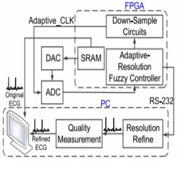
personal computer (PC) were used. Fig. 5
shows the block diagram of the verification
flow and experimental environment. First,
the ECG test patterns from MIT-BIH data
base [24] were downloaded to SRAM of the
FPGA board. Second, the testing ECG
signals in digital form were read from FPGA
board and then sent to a DAC device to
convert the signals to analog form by using
the highest sampling rate which was used to
avoid distortion of the testing ECG patterns.
Third, the ECG signals in analog form,
which were produced by the highest
sampling rate, were sent to the ADC device.
Fourth, the ADC converted the ECG signals
746 VOLUME 3, 2015 S.-L. Chen:
Power-Efficient Adaptive Fuzzy Resolution Control
System for WBSNs FIGURE 5. Block
diagram of the verification flow and
experimental environment for the proposed
adaptive fuzzy resolution control system. to
digital form by using the Adaptive_CLK
(HCLK, MCLK, or LCLK). Finally, the
digital ECG signals were sent to the
adaptive fuzzy resolution controller. After
decisions being made by the fuzzy
controller, a resolution control signal was
sent to down-sample circuits and a signal
Adaptive_CLK was produced as a sampling
clock of the ADC. Simultaneously, the
adaptive fuzzy resolution results were sent
to the PC through a RS-232 interface. After
receiving the data from the FPGA, the PC
refined the adaptive fuzzy resolution results
by using the fuzzy decision rule. Finally, the
refined and original ECG signals which
were read from SRAM of the FPGA board
were used to evaluate the quality of the
methodology. In the WBSN systems, the
base sampling rate and thresholds of
condition windows can be selected and set
by the users according to the characteristics
of each biomedical signal. In order to show
the performance of the proposed adaptive
fuzzy resolution control system, an
abnormal region of ECG signal in MIT-BIH
Arrhythmia data [24] was used as test
patterns. Since the abnormal region of ECG
signal was selected from MIT-BIH
Arrhythmia data, in which each ECG signal
has 360 samples per second, the 360 Hz was
selected as the high-resolution sampling rate
for simulation. In real applications, the users
can set the high-resolution sampling rate as
1024 Hz [16] or higher frequency [17]. The
original ECG signal of MIT-BIH
Arrhythmia data is 360 samples per second
and each sample is 11 bits. In this
simulation, the HCLK was set to produce
360 samples per second of the ADC. The
MCLK was down-sampled by HCLK as
well as LCLK is down-sampled by MCLK,
which is equivalent to produce 180 or 90
samples per second by the ADC. Fig. 6 (a)
shows the original ECG by 1000 sampling
points from MIT-BIH Arrhythmia data. Fig.
6 (b) shows the refined ECG results which
were produced by the proposed adaptive
fuzzy resolution control technique. First
sampling points were selected by using the
proposed adaptive fuzzy resolution
controller according to the relations of the
window-conditions. Second, the
down-sampled points were refined back to 1000
points by a linear interpolation as shown in
Fig. 6 (b). In this case, the conditions of
high-level condition window were set to
1250 as a high-level plus condition and 1000
as high-level minus condition. The
conditions of low-level condition window
were set to 800 as a low-level plus condition
and 750 as a low-level minus condition.
The Adaptive_CLK was selected from the
HCLK, MCLK, or LCLK by the adaptive
fuzzy resolution controller according to the
immediate feature of the ECG signal. Fig. 6
(c) shows the selected clock information and
the distribution of the transmitting power
consumptions in this case. To be able to
evaluate the qualities of the refined ECG
signals, a signal to noise ratio (SNR) was
used to quantify a noise approximation of
the refined signal and the original signal.
The SNR can be defined as SNR (dB) = 10
log10 Pn i=1 original(i) 2 Pn i=1
[original(i) − refined(i)] 2 (5)
where original(i) is ith sample of the original
the refined ECG signal. In order to show the
qualities of the adaptive fuzzy resolution
control, another measurement index peak
signal to noise ratio (PSNR) was also used
to measure the qualities of the refined ECG
signal and the original ECG signal. The
PSNR value can be obtained by PSNR (
dB)=10 log10 D 2 Pn i=1
[original(i) − refined(i)] 2 (6)
where original(i) is ith sample of the original
ECG signal, refined(i) is ith sample of the
refined ECG signal, and D is the maximum
peak-to-peak swing of the signal (2048 for
11-bit ECG signals). Fig. 6 (d) shows the
variation of PSNR value in this case. In
order to analyze the performance of the
proposed adaptive which was only designed
with window-conditions without using fuzzy
technology and the adaptive fuzzy resolution
controllers, six software models were
realized. The six models consist of the
variable resolution methodology of the
previous work [15], three adaptive sampling
methodologies based on slope [16]–[18], the
adaptive and adaptive fuzzy resolution
methodologies in this work. The technique
of the previous work [15] used the
threshold-conditions to select one of the
various clocks as the sampling clock of the
ADC, in which the H_CLK would be
selected as the sampling clock of the ADC
when the signal value is over the
threshold-conditions.
FIGURE 5. Block diagram of the
verification flow and experimental
environment for the proposed adaptive fuzzy
FIGURE 6. Simulation results of (a)
Original ECG signal by 360 1/s sampling
rate. (b) Simulation results of the ECG
signal with the proposed adaptive fuzzy
sampling rate design. (c) Selected clock
information and distribution of transmitting
power consumptions with the proposed
adaptive fuzzy resolution design. (d)
Distribution of PSNR with the proposed
adaptive fuzzy resolution design.
down sampled by the proposed fuzzy
algorithm, the signals should be refined by
the same fuzzy algorithm and inserting the
loss sampling points by the linear
interpolation. In order to evaluate the
qualities of the refined ECG signals by [15]–
[18] and the two methods of this work, a
signal to noise ratio (SNR) and a peak signal
to noise ratio (PSNR) were used to quantify
the refined signal and the original signal.
The adaptive sampling techniques [16]–[18]
selected one of the various sampling clocks
for the ADC according to the slope of the
ECG signals. In this work, two resolution
control techniques of adaptive and adaptive
fuzzy resolution control methods were
realized. The adaptive resolution control
method selects between the available
sampling clocks by determining which
condition-window the signal falls into, as
illustrated in Fig. 1. Otherwise, the adaptive
fuzzy resolution control method selects
between the available sampling clocks by
the fuzzy control rule in Table 1. Although
the operating frequency of the proposed
adaptive and the adaptive fuzzy resolution
controller designs achieved 100 MHz and
control signals within 10-ns, a period of
sampling delay was wasted when used
adaptive resolution control in this system.
The reason for this is the ADC cannot
achieve changing the sampling rate and
getting the new result simultaneously.
Hence, it spent a period of sampling delay
when the sampling rates of ADC are
changed. Table 2 lists the control
methodology, sampling rate, PSNR, SRN,
abnormal region PSNR, abnormal region
SNR, transmission data rate, and
transmission power consumption in these six
methodologies. The test region was set to
1000 sampling points. It was obtained from
MIT-BIH Arrhythmia data [24]. The
abnormal region was set to 100 sampling
points. The MCLK was 180 samples/s,
which was derived from HCLK with 360
samples/s. The LCLK was derived from
MCLK with 90 samples/s in the same way.
The adaptive and adaptive fuzzy control
methodologies in this work were selected
the sampling rate of the ADC from LCLK,
MCLK, or HCLK by the adaptive resolution
and the adaptive fuzzy resolution
techniques. The transmission data rates and
power consumptions were increased with
the sampling rate since the more data
consumed the more transmission power. The
PSNR value was improved to 2.28 dB, 16.07
dB and 22.21 dB in comparison with the
previous work [15]–[18] and the adaptive
fuzzy control of this work respectively. In
addition, the SNR value showed
improvement of 2.32 dB, 16.08 dB and
22.21 dB respectively. While in the
abnormal region is also advanced to 15.47
dB, 26.31 dB and 31.44 dB in PSNR and
SNR respectively. According to our
previous experience [14], it consumes
10-µW to transmit a bit through a transmitter
and modulator. The transmission power
consumptions in Table 2 were evaluated by
products of the transmission data rates and
transmission power consumption per bit.
The evaluated transmission power
consumption of the proposed adaptive fuzzy
controller is 14.3-mW, which is lower than
16.28-mW and 14.61-mW in the previous
works of [15] and [17], [18], respectively.
Comparing the results of the adaptive and
adaptive fuzzy control methodologies in this
work, the fuzzy control technique improved
PSNR or SNR value by 1.9 dB or 1.34 dB
when an abnormal situation occurs and only
increases 1.4% of power consumption. The
proposed two controller designs namely,
adaptive and adaptive with fuzzy control,
description language (HDL). The electronic
design automation (EDA) tool, Design
Vision, was used to synthesize the VLSI
circuit based on TSMC 0.18-µm process
standard cells. The auto placement and
routing tool IC Compiler was used to
generate the layout of the proposed two
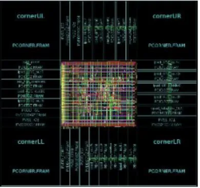
controller designs. The photo of chip layout
with pads of the proposed adaptive fuzzy
resolution controller is illustrated in Fig. 7.
Synthesis results show that the adaptive and
adaptive fuzzy resolution controller design
contains 203 and 539 NAND-equivalent
gate counts, respectively. The synthesized
area of the proposed adaptive or adaptive.
FIGURE 7. The photo of chip layout with
pads.
fuzzy resolution controller is 3,376-µm2 and
7,124-µm2 , respectively, which has been
synthesized by the 0.18-µm CMOS process.
The power consumption of the proposed
designs was measured by using SYNOPSYS
PrimePower. It consumes 2.2-µW and
4.2-µW of the adaptive and adaptive fuzzy
resolution controllers, respectively, at
1-MHz operating frequency with 1 V supply
voltage. The specifications of the proposed
two controller designs are listed in Table 3.
ADC in [14] was realized by the 0.18-µm
CMOS process and its core area is
0.217-mm2 with the power consumption of
216-µW when it operates at 1 MHz. By
combining the proposed adaptive and
adaptive fuzzy controller design with the
ADC in the previous work, the total areas
are 0.2204-mm2 and 0.2241-mm2 ,
respectively. In addition, the power
consumption of the two controllers is
218-µW and 220-218-µW. Table 4 lists the
comparison results of two previous VLSI
designs with this work. In order to compare
with the previous design [16] objectively,
the power consumption and core area listed
in Table 4 were considered the ADC and
sampling controller circuits only without
including the analog front end and radio
circuits. Also, the power consumption and
core area in [17] listed in Table 4 included
the function of the variable sampling rate by
using the ASP to execute the sampling
control program. As compared with the two
previous designs, [17] including only ADC
and ASP partitions as well as [16] including
ADC and sampling controller, this work
reduced at least 96.7% and 33.3% core area,
which were normalized by 0.18-µm process,
than the previous designs of [16] and [17],
respectively. The adaptive fuzzy resolution
controller achieved not only improving the
SNR or PSNR values by at least 15.47 dB in
abnormal region but also reduced 62.6%
core area in the proposed ECG monitoring
application. Thus, the proposed adaptive
fuzzy resolution control system has the
characteristics of low-power,
high-performance, and cost-efficient. It provides
a well base to develop a mixed signal chip
including adaptive fuzzy controller, ADC,
devices and circuits with more functions for
healthcare monitoring sensing systems and
wireless body sensor networks
CONCLUSION :
A new method adaptive control system
using fuzzy logic had been presented for a
wireless body area network (WBAN). For
WBAN, along with wireless body sensor
node an adaptive fuzzy resolution controller
was added for better performance. The
results show that this can improve the
quality of ECG signals in abnormal region.
It also reduces the transmission power for
wireless body sensor networks. And also the
proposed adaptive fuzzy resolution control
system has the characteristics of low-power,
high-performance, and cost efficiency.
ACKNOWLEDGMENT Authors would
like to express special thanks to teachers for
providing an excellent guidance in the
research, parents and friends who help a lot
for finalizing the work. Finally sincere
thanks to God who is the power of the
strength in each step of progress towards it
successful completion.
REFERENCES
[1] Shih-Lun Chen, “A Power-Efficient
Adaptive Fuzzy Resolution Control System
For Wireless Body Sensor Networks”, IEEE
ACCESS, vol.3, pp.743-751,2015.
[2] Sana Ullah, Pervez Khan et.al “A
Review of Wireless Body Area Networks
for medical applications,” International
Journal. of Communications, Network and
System Sciences (IJCNS), vol. 2, no. 8:
[3] Prakashgoud Patil and Samina Mohsin,“
fuzzy logic based health care system using
wireless body are networks” International
Journal of Computer Applications, vol 80,no
12,2013
[4] C.A. Chen, S.L. Chen, et al., “An
Asynchronous Multi-Sensor Micro Control
Unit For Wireless Body Sensor Networks
(WBSNs),” Sensors, vol. 11, no. 7, pp.
7022_7036, 2011.
[5] Shih-Lun Chen, “ A Reconfigurable
Control System Design for Wireless Body
Sensor Network” Asia-Pacific Conference
on Computer Aided System Engineering
(APCASE), pp.127_130.
[6] S.L. Chen, H.Y. Lee, et al., “A Variable
Control System For Wireless Body Sensor
Network,” Proc. IEEE International
Symposium Circuits System Conference
(ISCAS), Seattle, WA, USA, pp.
2034_2037, 2008. [7] Robert Kerwin C.
Billonesa and Elmer P. Dadiosa, “Fuzzy
Inference System for Remote Health
Monitoring Using Wireless Body Area
Networks”.
[8] Ado Adamou ABBA ARI , Abdelhak l.,
“Concepts And Evolution Of Research In
The Field Of Wireless Sensor Networks” in
International Journal of Computer Networks
& Communications (IJCNC) Vol.7,
no.1,2015
[9] S.-L. Chen, H.-Y. Lee, A. Chen,
C.-C. Lin, and C.-C.-H. Luo, "A Wireless Body
Sensor Network System for Healthcare
Monitoring Application", presented at IEEE
Biomedical Circuits and Systems
Conference (BIOCAS), 2007.
[10] Yun-Chi Yeh,, “An Analysis of ECG
for Determining Heartbeat Case by Using
the Principal Component Analysis and
Fuzzy Logic” International Journal of Fuzzy