R E S E A R C H
Open Access
Analysis, optimization, and implementation of a
hybrid DS/FFH spread-spectrum technique for
smart grid communications
Mohammed M Olama
1*, Xiao Ma
2, Stephen M Killough
1, Teja Kuruganti
1, Stephen F Smith
1and Seddik M Djouadi
2,3Abstract
In recent years, there has been great interest in using hybrid spread-spectrum (HSS) techniques for commercial applications, particularly in the Smart Grid, in addition to their inherent uses in military communications. This is because HSS can accommodate high data rates with high link integrity, even in the presence of significant multipath effects and interfering signals. A highly useful form of this transmission technique for many types of command, control, and sensing applications is the specific code-related combination of standard direct sequence modulation with‘fast’ frequency hopping, denoted hybrid DS/FFH, wherein multiple frequency hops occur within a single data-bit time. In this paper, error-probability analyses are performed for a hybrid DS/FFH system over standard Gaussian and fading-type channels, progressively including the effects from wide- and partial-band jamming, multi-user interference, and varying degrees of Rayleigh and Rician fading. In addition, an optimization approach is formulated that minimizes the bit-error performance of a hybrid DS/FFH communication system and solves for the resulting system design parameters. The optimization objective function is non-convex and can be solved by applying the Karush-Kuhn-Tucker conditions. We also present our efforts toward exploring the design, implementation, and evaluation of a hybrid DS/FFH radio transceiver using a single field-programmable gate array (FPGA). Numerical and experimental results are presented under widely varying design parameters to demonstrate the adaptability of the waveform for varied harsh smart grid RF signal environments.
Keywords:Hybrid spread-spectrum; Direct sequence; Frequency hopping; Smart grid communications; Non-convex optimization; Receiver sensitivity; FPGA
1 Introduction
Hybrid spread-spectrum (HSS) systems, which combine direct-sequence (DS) and frequency-hopping (FH) spread-spectrum (SS) techniques, are attractive for their strong multiple-access capabilities, resistance to multipath fading and intentional/unintentional jamming, and the security they provide against eavesdroppers [1-6]. In recent years, there has been great interest in using HSS systems for com-mercial applications, particularly in the Smart Grid.
User requirements for the next generation wireless com-munication system have been specified for the Smart Grid advanced metering infrastructure (AMI) and distribution
automation systems [7]. These requirements demonstrate the need for high capacity and highly secure networks for Smart Grid applications. There is a significant gap be-tween commercially available communications systems and those needed to satisfy the demanding requirements associated with electric utility industry. HSS systems are a promising candidate for Smart Grid applications since they provide high data rates with excellent signal security.
Spreading the signal over a relatively wide bandwidth al-lows transmission with relatively low power density, lead-ing to low probabilities of detection and interception. HSS systems also provide an inherent security against eaves-droppers because knowledge of the spreading codes is required. The choice of appropriate pseudo-noise (PN) codes and dynamic altering of signal parameters provides the opportunity for a strong security scheme in the * Correspondence:[email protected]
1
Computational Sciences and Engineering Division, Oak Ridge National Laboratory, P.O. Box 2008, MS 6085, Oak Ridge, TN 37831, USA Full list of author information is available at the end of the article
physical (PHY) layer of the network [5]; details of these techniques will be addressed in future works. This specific paper will focus on implementation, exploration, and optimization of the parameter space of the HSS system for adapting the technique for application-level requirements in Smart Grid.
Based on the hopping rate, an HSS system is classified into a hybrid direct-sequence/slow frequency hopping (DS/ SFH) system or a hybrid direct-sequence/fast frequency hopping (DS/FFH) version. In hybrid DS/FFH systems, multiple frequency hops occur within a single data-bit time. Specifically, each bit is represented by chip transmissions at multiple frequencies. If one or more chips are corrupted by multipath or interference in the RF link, statistically a ma-jority should still be correct. Standard or slow frequency hopping, in contrast, transmits at least one (and usually several) data bits in each hopping interval. DS/FFH systems have not been previously widely implemented in many commercial or industrial applications since fast frequency-hopping rates were limited by the technology of frequency synthesizers. Today’s extremely fast hopping speed direct-digital synthesizers (DDSs) [8] are rapidly becoming an al-ternative to the traditional frequency-agile analog-based phase-locked loop (PLL) synthesizers. Output frequencies with micro-Hertz resolution and sub-degree phase tuning capabilities can thus be readily achieved using a single inte-grated circuit (IC).
Most of the works related to HSS in the literature have addressed evaluating its performance under differ-ent modulation techniques [2], channel conditions [1,3], multi-user interference [2,3], and jamming [4]. How-ever, little research has yet evaluated the performance of a hybrid DS/FFH system under all combinations of the aforementioned cases. Moreover, few efforts have to date attempted to address the design and selection of the HSS system parameters that achieve optimal per-formance. The work in this paper extends the one in [9] and [10] from a DS system to a hybrid DS/FFH system, in addition to taking jamming impacts into consider-ation. In [11], the performance of a SFH system was considered. In [2] and [12], the performance of a DS/ SFH system over an AWGN channel and with multi-user interference was considered. The performance of an FFH system over fading channels was examined in [13] and extended in [3] to include the effects of partial-band noise jamming. Although [4] and [14] computed the error probability of DS/SFH under jamming tones in both AWGN and Rician fading channels, only a sin-gle user was considered. In [15], the optimal spreading sequences for chip-synchronous CDMA are derived by minimizing the average bit error rate under the standard-Gaussian-approximation condition. The work in [16] presents a simulation-based study for evaluating the performance of a hybrid DS/FFH scheme. Some preliminary
performance analysis and hardware designs for the hybrid DS/FFH scheme were initially presented in [17-19].
In this paper, error-probability analyses are performed for a hybrid DS/FFH system over standard Gaussian and fading-type channels, progressively including the effects from wide- and partial-band jamming, multi-user interfer-ence, and varying degrees of Rayleigh and Rician multipath fading. We present analytical derivations for evaluating the performance in terms of probability of bit error. In addition, an optimization approach is formulated that mini-mizes the average bit-error probability of a hybrid DS/FFH communication system and solves for the system design parameters that achieve an optimal performance level. The optimization objective function is non-convex and can be solved by applying the Karush-Kuhn-Tucker (KKT) condi-tions [20]. We also present our efforts toward exploring the design, implementation, and evaluation of a hybrid DS/ FFH radio transceiver using a single field-programmable gate array (FPGA). Numerical and experimental results are presented under widely varying design parameters to dem-onstrate the adaptability of the waveform for varied harsh smart grid RF signal environments.
2 System model
Assume that there are a total of Knodes that represent smart meters or data aggregation points in the Smart Grid wireless network. For thekth node, the transmitted signal is given as
skð Þ ¼t pffiffiffiffiffiffi2Pbkð Þt akð Þt cos2πfcþfkhð Þt t ð1Þ where P is the common transmitted signal power,fc is
the carrier frequency, fkhð Þt denotes the hopping fre-quency of the kth node, the data signal bk(t) is a
se-quence of statistically independent, unit-amplitude positive, and negative rectangular pulses of durationTb,
and ak(t) is the PN-code waveform for thekth node in
DSSS and is given as akð Þ ¼t
X∞
n¼−∞a k
nPTcðt−nTcÞ; where akn is the discrete periodic signature sequence assigned to thekth node and PTcð Þt is a rectangular pulse that starts att= 0 and ends att=Tc.
Consider M frequency hopping channels with L (as-sume L is odd) hops per bit. Let T=Tb/L denote the
duration of each hop and Tc= Tb/NL denote the chip
duration for the PN-code sequence, where N is the period of the PN-sequence and is also assumed to be odd. The wide-band jamming fully corrupts W hopping channels and another single channel partially (letWPJ be the part of the channel affected by the partial jamming).
y tð Þ ¼X AWGN term that have two-sided spectral densitiesNJ/2
andN0/2,, respectively, and
rkð Þ ¼t γk
where the nonnegative real parameter γk is the Rician
channel coefficient for the kth node; βk(τ,t) is a
zero-mean complex Gaussian random process that represents the equivalent low-pass time-varying impulse response for the fading channel [10]. The covariance function for the fading process in a WSSUS channel is [22,23].
Λkðτ;σ;t;sÞ ¼
In this paper, we focus on one class of WSSUS chan-nels known as time-selective fading chanchan-nels [22]; its co-variance function is given by ρk(τ,t−s) =ρk(0,t−s)δ(τ)
Similar to [24], the time delays and data symbols for the kth node are modeled as mutually independent ran-dom variables which are uniformly distributed on [0,T] and {−1, + 1}, respectively. We also assumeτi= 0 when
considering the output of the kth (k≠i) correlation receiver.
3 Error probability analysis
In this section, we first investigate the average error probability for one hop, and then we employ a majority voting scheme to compute the overall error probability for one bit.
For each userk, the other K-1 users are considered as interference. Three different situations may occur in one hop:j out ofK-1 users interfere with the same hopping channel of userkand (1) no jamming corrupts the chan-nel, (2) jamming fully corrupts the chanchan-nel, or (3) jam-ming partially corrupts the channel. Thus, the total average error probabilityPk
ε of one hop for userkcan be
where PkεðjusersÞ is the average error probability of one hop due to jinterfering users. Expression (6) is equiva-lent to given events a and b have occurred. From the problem formulation, we can obtain:
P jðusers;no jamÞ ¼ K−1
The conditional error probabilities for each case of jamming over Rician fading channels are discussed next.
A.Case 1: No Jamming
When there is no jamming, the error probability for BPSK modulation is given as [25]:
Pkðεjjusers;no jamÞ ¼Q ffiffiffiffiffiffiffiffiffiffiffiffiffiffiffiffiffiffiffiffiffiffiffiffi1
whereIkj is the interference-to-signal ratio introduced by the other users hopping in user k’s channel, NSR=N0/
Ikj ¼
aperiodic autocorrelation function for the PN-sequence. Different PN-sequences correspond to different aperi-odic autocorrelation functions which are functions of the lengthNof the sequence. In this work, we employ a maximal-length sequence (MLS) as the signature se-quence. However, by using an MLS code, there does not exist a closed-form expression of the aperiodic autocor-relation function,Ri(l), for the general MLS code, which
prevents us from finding a closed-form expression forIkj. However, we can compute a closed-form expression if we know exactly which MLS code is used. Actually, two dif-ferent MLS codes with the same length will have differ-ent aperiodic autocorrelation functions. Therefore, we consider an upper bound on an MLS’s aperiodic auto-correlation function derived in [26] to compute an upper bound on the error probability of the HSS system. From [26], we have Ri(0) =N and Rið Þl <Ru¼1þ2π
Nþ1
ð Þ1
2In 4N
π ;l≠0. Plugging them back into Ikj in (10)
and assumingγk=γas a constant for simplicity, we get
an upper bound onIkj as: B.Case 2: Full Jamming
When jamming fully corrupts the userk’s channel, the error probability for BPSK is given as:
Pkð jεjuser;full jamÞ ¼Q ffiffiffiffiffiffiffiffiffiffiffiffiffiffiffiffiffiffiffiffiffiffiffiffiffiffiffiffiffiffiffiffiffiffiffiffiffiffiffiffiffiffi1
whereJSR=NJ/2PTis the jamming-to-signal ratio.
C.Case 3: Partial Jamming
When jamming partially corrupts the userk’s channel, the error probability includes two portions: one is the part of the channel corrupted and the other is the un-corrupted part. Let q¼WpJ=ðN WbÞdenote the fraction
of the channel jammed, whereWb= 1/Tb. Then the error
probability for the BPSK case is given as:
Pkðεjjusers;partial jamÞ ¼q Pkðεjjusers;full jamÞ þð1−qÞPkðεjjusers;no jamÞ
ð13Þ
Based on the arguments above, the error probability per hop, Pkε, is obtained. Without loss of generality, we assume the Rician channel coefficients for all users are identical, i.e.,γk=γ, then, for simplicity,Pkε can be
repre-sented as Pε. To compute the error probability for one bit, denoted PE, we employ a majority voting decision
scheme given as:
Due to the monotonicity of Q(•), using (11) provides an upper bound on Pk
ε and thus an upper bound onPE.
The problem of determining the HSS system parameters for an optimal performance is now discussed in the next section.
4 Optimization problem formulation
In realistic HSS systems, the overall system performance always suffers from practical parameter constraints. Thus, we formulate the problem of minimizing the bit-error performance subject to some representative par-ameter constraints.
The system design parameters of interest are the number of frequency-hopping channelsM, the length of the PN-sequence N, the number of channels fully cor-rupted by jammingW, and the number of hops per bit
L. Assume that these parameters satisfy the following constraints
W−K2M≥0; 0≤K2≤1 ð16Þ
K3− 1
LWb ≤0; K3>0 ð17Þ
M;N;W;L>0 ð18Þ
together with integer constraints on the parameters (i.e.,
M,N,W,Lare positive integers).
The physical meaning of these constraints can be ex-plained as follows: (15) represents that the total bandwidth of the system (MNWb) is limited byK1, whereK1> 0; (16)
means that the number of frequency channels fully cor-rupted by the jamming are a portion of the total number of channels, where 0≤K2≤1; (17) provides a lower bound on
the time duration of each hop 1 LWb
due to
implementa-tion limitaimplementa-tions; and (18) restricts all the parameters to be positive.
The optimization problem is to minimize the system’s bit- error rate (BER) in (14) with respect to the con-straints described in (15) to (18). It can be written as:
min
M;N;W;L
P
Esubject to 15ð Þ;ð Þ16 ;ð Þ17;ð Þ18
ð19Þ
The integer constraints are removed in the problem statement and the following analysis because they can be imposed after the solutions of (19) are found. This will be discussed in more detail in the following section.
5 Necessary conditions of the optimization problem
By examining the structure of PE, we can further relax
the constraint (17). NotePEis a monotonically
decreas-ing function with respect toL, so constraint (17) can be written as:
L≤ 1
K3Wb
ð20Þ
which means that there is an upper bound onL. More-over, as Pε does not depend on L, the error probability PE reaches its minimum when L¼K31Wb with the other
parameters fixed.
Further, it is easy to see that PE is a monotonically
increasing function with respect to Pε on the interval
[0, 1], and M, N, W are all contained only inPε; thus,
the optimization problem in (19) can be further simplified as:
min M;N;W
P
εsubject to 15ð Þ;ð Þ16;ð Þ18
ð21Þ
From Section 3, we have
Pε¼
XK−1
j¼0
PnPnjþPfPfjþPpPpj
ð22Þ
where Pn=P(jusers, no jam), Pf=P(jusers, full jam),
Pp=P(jusers, partial jam), Pnj=Pk(ε|jusers, no jam),
Pfj=Pk(ε|juser, full jam), Ppj=Pk(ε|jusers, partial jam).
Expression (22) can be further simplified by representing
Ppjin terms ofPnjandPfjas follows:
Pε¼
XK−1
j¼0
PnþPpð1−qÞ
Pnjþ PpqþPf
Pfj
ð23Þ
For convenience, let
Pε;j¼ PnþPpð1−qÞ
Pnjþ PpqþPf
Pfj ð24Þ
and also letx= (M,N,W).
From Section 3, we observe thatPnandPfare functions
of bothMandW, whilePpis only a function ofM.
More-over,Pnj andPfj are functions ofN. We can also observe
that the error probability to be minimized has a complex structure and is a non-convex function. Thus, to compute the optimal solution, we apply the Karush-Kuhn-Tucker (KKT) [20] conditions to problem (21).
Lemma 1:(Karush-Kuhn-Tucker Conditions) Let y*be
a local minimum of the following problem
min f yð Þ
subject tog1ð Þy ≤0;…;gmð Þy ≤0 ð25Þ
where f and gi are continuously differentiable functions
with appropriate dimensions. Then there exists an unique Lagrange multiplier vectorμ= (μ1,…,μm),such that
∇yR yð ;μÞ ¼0;
μi≥0;i¼1;…m;andμi¼0;∀i∉A yð Þ
ð26Þ
where R yð ;μÞ ¼f yð Þ þXm
i¼1μigið Þy is the Lagrangian function and A(y*) is the set of active constraints at y*
defined as: For any feasible vector y (the vector that sat-isfies all constraints), the set of active inequality con-straints is given as A(y) = {i|gi(y) = 0}and if j ∉A(y),it is
said that the jth constraint is inactive at y.
In addition, if fandgiare twice continuously
differenti-able, then there holds zT∇2
Now, the necessary conditions for a local minimum of problem (21) can be derived by applying the KKT condi-tions as follows:
In addition, the following inequality holds:
1
In order to apply the KKT conditions, we first need to check the types of inequality constraints, to determine whether they are active or inactive inequality constraints.
It is obvious that (18) is inactive at x*. To check for (15), first assume that (15) is also inactive at x*, which infers M*N*Wb−K1< 0. However, it should be noted
that Pε is a monotonically decreasing function with
respect to both M* and N*; thus, M*N*Wb−K1< 0
means there is still an ‘increasing space’ for either M* or N*, such that Pε can still be reduced by increasing M* or N* to M*N*Wb=K1, which contradicts that x*
is the local minimum. Thus, (15) is an active con-straint atx*.
To check for (16), first assume that (16) is inactive atx*, which means W*−K2M* > 0, by applying the KKT
neces-sary conditions (page 316, Proposition 3.3.1 in [20]), we have the unique Lagrange multiplier for (16) μ2= 0 and
XK−1
tion. Thus, (16) is also an active constraint atx*.
After specifying the type of each inequality constraint, we can obtain Theorem 1 by applying the KKT condi-tions in Lemma 1 to problem (21).
Remark 1 We can similarly obtain second-order
suffi-ciency conditions of the problem by applying the following KKT sufficient conditions (page 320, Proposition 3.3.2 in
[20]): If (27)to(37)hold for some x and μi> 0, i= 1,…
m,then x is a strict local minimum.
Remark 2Once the solution is found, the integer
con-straints need to be imposed. For example, assume M, N,
W, L are positive integers; first, round one parameter (e. g.,N) to the nearest integer, then plug it back to the prob-lem and re-compute the solution. After that, round the rest of the parameters in a similar fashion.
Theorem 1 states the necessary conditions for the optimization problem by employing a general PN-sequence. Now, we will employ the MLS code as the PN-sequence in the HSS system and reformulate Theorem 1 explicitly.
Expression (11) describes that Ikj for an MLS code is upper-bounded by Iuj. Note that the upper bound of the error probability reserves the same monotonicity with respect to the system parameters (e.g., M, N). Consider-ing the upper bound Iuj in (11), Theorem 1 remains the
same, with the exception that ∂I k j
∂N is replaced with
∂Iu j
∂N.
After performing some derivations, we obtain:
I2¼
Plugging the above equations back into Theorem 1, then we can obtain necessary conditions for the local minimum of the upper bound of the error probability for the MLS code. Sufficient conditions can also be ob-tained from Remark 1.
Remark 3 Note that in an MLS code, N is an integer
such that N= 2n−1 where n is a positive integer. Thus, after obtaining solutions of the local minimum of the problem, N in each solution should be rounded to the closest integers in the form of2n−1 (usually two integers correspond to N in one solution), and the rest of the pa-rameters in the solution should be re-computed and rounded. Then, by comparing the error probabilities re-sulted from these two sets of parameters, we employ the parameter set with the lower error probability as the local minimum of the problem after re-applying the inte-ger constraints.
In the next section, our specific design and implemen-tation of a hybrid DS/FFH radio transceiver using a sin-gle FPGA are presented.
6 ORNL specific hybrid DS/FFH design and implementation
The hybrid DS/FFH prototype was designed to demon-strate the fundamental advantages of the HSS system, such as jamming resistance, difficulty of unwanted inter-ception, robust performance, and reasonable cost. The prototype operates in the unlicensed 902 to 928 MHz ISM band, although target applications such as the SG may ultimately use a dedicated frequency band. The sys-tem parameters for the prototype are selected based on the available ISM bandwidth and FPGA capabilities and using the analysis presented in the previous section. The selected parameters are considered to be nearly optimal for a typical smart grid environment.
We decided to use the Software Defined Radio (SDR) method for hardware implementation of the hybrid DS/ FFH system because of its flexibility in changing the sys-tem to evaluate new concepts. This methodology has also proven to be very powerful in that the vast majority of the signal processing components can be placed in a single FPGA. The entire HSS band is down-converted to an intermediate frequency, digitized, and sent to the FPGA. Within the FPGA, look-up-table-based local os-cillators down-convert the individual FH channels to baseband. These baseband signals are then decoded using DS correlators and stored in a buffer for subse-quent delivery to a host computer.
As shown in Figure 1, the HSS unit splits the 902 to 928 MHz band into ten separate FH channels, each of which sends a DS spread spectrum signal with a 1.25-MHz chip-ping rate. An analog mixer converts these frequencies up or down for the transmitter or receiver, respectively, for use by the digital-to-analog (D/A) or analog-to-digital (A/D)
903.75 906.25 908.75 911.25 913.75 916.25 918.75 921.25 923.75 926.25
12.5 15.0 17.5 20.0 22.5 25.0 27.5 30.0 32.5 35.0
Figure 1The prototype RF and FPGA frequencies in MHz.
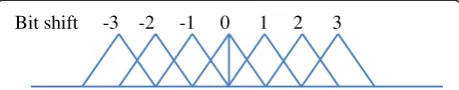
Bit shift -3 -2 -1 0 1 2 3
converters. The SDR algorithms work over a designated 12.5 to 35.0 MHz frequency range. Each DS signal is a 63-bit length MLS code, although more advanced Gold or Kasami codes could also be used. Three hops per bit are used, and at the receiver a two-out-of-three majority voting decision scheme is employed.
Of particular, interest is the method used for modulat-ing the DS signal. Traditional PSK modulation requires a preamble at the beginning of the packet to determine the reference phase and a Costas Loop [27] or similar mechanism to maintain this phase reference. With HSS in multipath channels, this phase reference is lost after each frequency hop; therefore, we decided to perform the DS modulation by shifting the start time of the code. The incoming signal is correlated with local copies of the shifted code pattern and an early-late voting system determines the amount of shift of the received signal. The correlation algorithm is independent of the carrier phase of the signal. The number of bits that can be encoded by this method is demonstrated by the early-late diagram described in Figure 2.
The bit-shift number refers to the number of bits that the local DS code has been shifted for performing the correlation. To prevent ambiguous results from a correl-ation being between two bits, only every other bit
position is used, which results in 31 positions available for each code word. Four bytes of blank data are sent at the beginning of the packet as a preamble to set the ref-erence DS start time.
A different interpretation of this methodology would be that the DS code is shifted because of a different time-of-flight, similar to GPS or continuous wave radar. Similar to the way GPS can achieve precise time-of-flight resolution, it can be expected that this methodology can be further de-veloped to obtain higher bit capacity. The work in [28] ex-plores this method for multiple users occupying a channel simultaneously.
The HSS channel capacity is calculated by dividing the chip rate, or 1.25 MHz, by the 63-bit code length to get 19,841 DS sequences per second. Since the data is repli-cated three times for redundancy, the actual throughput is 6,613 DS sequences per second. Since each DS se-quence contains 8 bits of data, the data throughput is 52,910 bits per second. The HSS prototype is optimized for reading household utility meters for smart grid appli-cations and thus only requires 32 bytes, although the system has operated successfully with 256-byte packets.
The prototype hybrid DS/FFH system is based on a Xilinx Virtex-4 FPGA for performing the digital signal pro-cessing. The hardware setup is described in Figure 3. The
Rx Signal Tx Signal To Host
Computer
PIC32 Micro-Computer
Xilinix FPGA
Local Oscillator 891.25 MHz D/A
A/D
BPF
BPF LPF
Figure 3Hardware setup for the hybrid DS/FFH prototype.
35MHz
32.5MHz
12.5MHz
Hop Pattern
90
deg Data
Buffer
½ Bit Delay
Code Delay Modulation
Code Delay Modulation
DS Code A
DS Code B D/A
. . .
FPGA, A/D, and D/A operate synchronously together at 100 MHz to allow operation on analog signals to a prac-tical limit of 40 MHz. The D/A has 16-bit resolution for a dynamic range of 96 dB, and the corresponding A/D has 14-bit resolution for a dynamic range of 84 dB. The micro-computer loads and unloads data to the FPGA and com-municates with sensors and other computers using Ethernet, RS232, or analog signals.
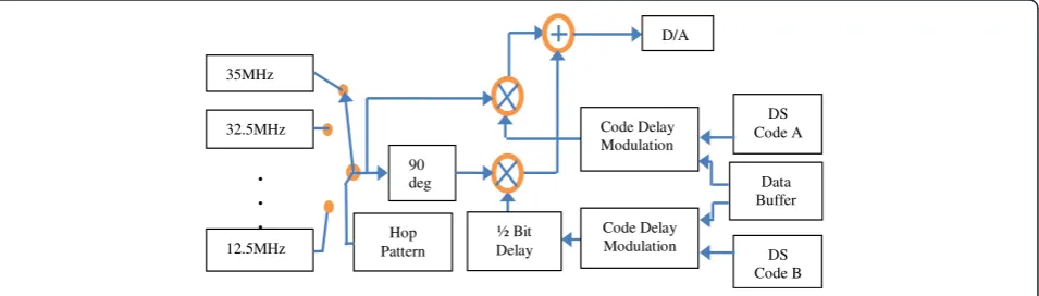
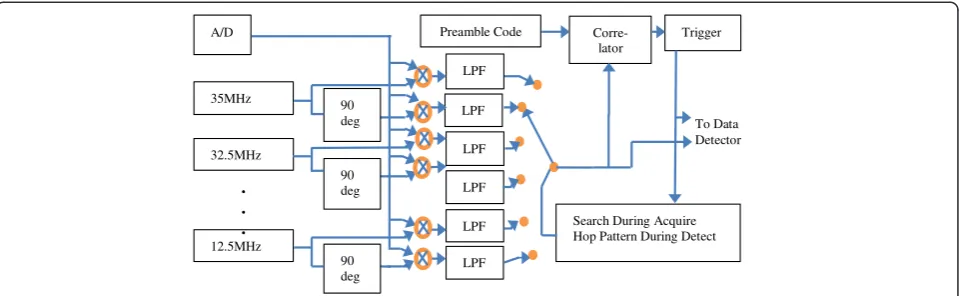
Figure 4 describes the transmitter portion of the FPGA code, which consists of the data buffer, modulator, and ten local oscillators for generating the hopping carriers. Raised-cosine waveshaping is used to reduce the spectral sibands. The receiver uses the same local oscillators for de-tecting signals, and all ten channels must be simultaneously
received to detect the preamble during jamming situations as illustrated in Figure 5.
To acquire the packet preamble, a spread-spectrum correlator continually looks for the preamble pattern on all channels. Once the preamble is detected, an in-ternal timing sequence compares the signal with shifted copies of the DS code via a simple correlator. The shifted copy of the DS code that provides the strongest correlation then demodulates the actual data. To make the signal detection independent of the carrier phase, both phases of the carrier (I and Q) are correlated with the preamble’s code. However, the phase relationship must remain consistent during the duration of the DS sequence.
LPF LPF LPF
LPF
LPF LPF
To Data Detector Preamble Code
Search During Acquire Hop Pattern During Detect
Corre-lator
Trigger A/D
35MHz
32.5MHz
12.5MHz
90 deg
90 deg
90 deg .
. .
Figure 5Preamble-detection section of the receiver.
0 2 4 6 8 10
-200 -150 -100 -50 0 50
Frequency (MHz)
Magnitude (dB)
LPF Freq. Response
Received SS Signal
A key limitation of the radio’s selectivity is the digital low-pass filter (LPF) implemented in the FPGA. Because we were limited to integer arithmetic in the FPGA, the filter was implemented as a simple square-window FIR LPF, with four of the filters connected in series. A future implementa-tion of HSS could use a newer generaimplementa-tion FPGA with floating-point arithmetic to achieve a filter with better rolloff characteristics and higher ultimate rejection. Figure 6 is an
analytically generated plot of the low-pass filter response, superimposed on the frequency spectrum of the spread-spectrum signal. The ultimate rejection level of 70 dB will be apparent in the experimental results presented in the next section.
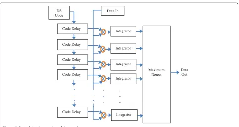
Once the packet start has been established, the receiver begins listening on specific channels instead of all channels. A simple multiply-and-integrate correlator system is used
. . .
. . . Integrator
Integrator
Integrator
Integrator
Integrator
Maximum Detect
Data Out Data In
. . . DS Code
Code Delay
Code Delay
Code Delay
Code Delay
Code Delay . . .
Figure 7Data-detection section of the receiver.
5 10 15 20
10-5 10-4 10-3 10-2 10-1
SNR(dB)
E
rr
o
r
P
robabi
lit
y
80 users 100 users 120 users 140 users
for signal detection as illustrated in Figure 7. In the next section, we present experimental results to demonstrate the performance of the hybrid DS/FFH prototype.
7 Numerical and experimental results
7.1 Hybrid DS/FFT system performance
We first demonstrate the performance of a hybrid DS/FFH system over Rician time-selective fading channels, progres-sively including the effects from wide- and partial-band jamming, multi-user interference, and varying degrees of
Rician fading. The performance measure is the upper bound of BER described in (14) by employing (11). The pa-rameters of the reference system model considered in this numerical example are total number of users is K= 100; number of hops per bit is L= 5; number of frequency-hopping channels is M= 30; period of PN-sequence in DSSS is N= 127; jamming-to-noise ratio (JNR) is 13 dB; number of channels fully jammed is 5; the Rician channel coefficient γ= 0.1 (represents the channel fading part); channel covariance function scaling factorλ= 10.8; and the
5 10 15 20
10-4 10-3 10-2 10-1
SNR(dB)
E
rr
or
P
robabi
lit
y
JNR=10dB JNR=13dB JNR=14.7dB JNR=16dB
Figure 9Performance of a hybrid DS/FFH system.Effect of different jamming-to-noise ratios (JNRs).
5 10 15 20
10-4 10-3 10-2 10-1
SNR(dB)
Er
ro
r Pr
o
b
a
b
ili
ty
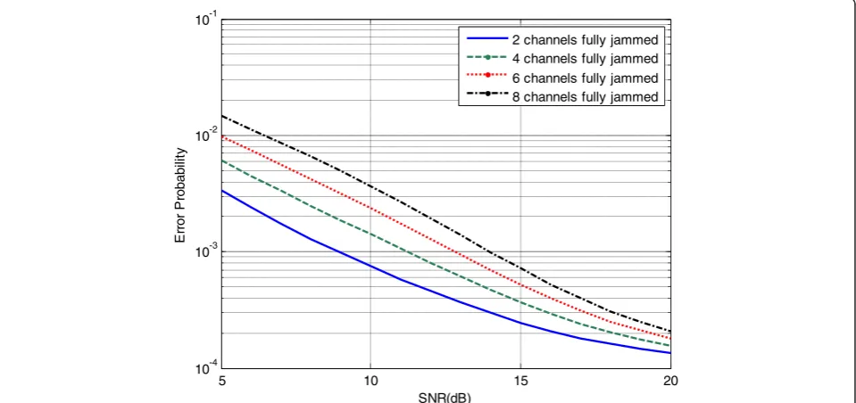
2 channels fully jammed 4 channels fully jammed
6 channels fully jammed 8 channels fully jammed
portion of the channel partially corrupted is 0.4. The par-ameter space of the HSS system is explored to demon-strate its effectiveness under different conditions and scenarios. In the following analysis, we successively vary one parameter in the reference system model while fixing the other parameters.
Figure 8 shows the effect of different number of continu-ously transmitting users (multi-user interference) on the performance of a hybrid DS/FFH system. You can observe the high multiple access capability of such a technique,
especially at high SNRs. Figure 9 demonstrates the per-formance for different jamming to noise ratios (JNRs), and Figure 10 demonstrates the performance for vary-ing number of fully jammed channels. You can observe from Figures 9 and 10 the high anti-jamming capability of such a technique, especially at high SNRs. Also, it can be observed that under high SNRs the performance gap re-duces for different JNRs and different numbers of fully jammed channels. Figure 11 demonstrates the performance for different numbers of hops per bit. Notice that the
5 10 15 20
10-5 10-4 10-3 10-2 10-1
SNR(dB)
E
rr
o
r
P
ro
b
a
b
ilit
y
7 hops/bit 5 hops/bit 3 hops/bit 1 hop/bit
Figure 11Performance of a hybrid DS/FFH system.Effect of different number of hops per bit.
5 10 15 20
10-5 10-4 10-3 10-2 10-1
SNR(dB)
E
rr
o
r
P
ro
b
a
b
ilit
y
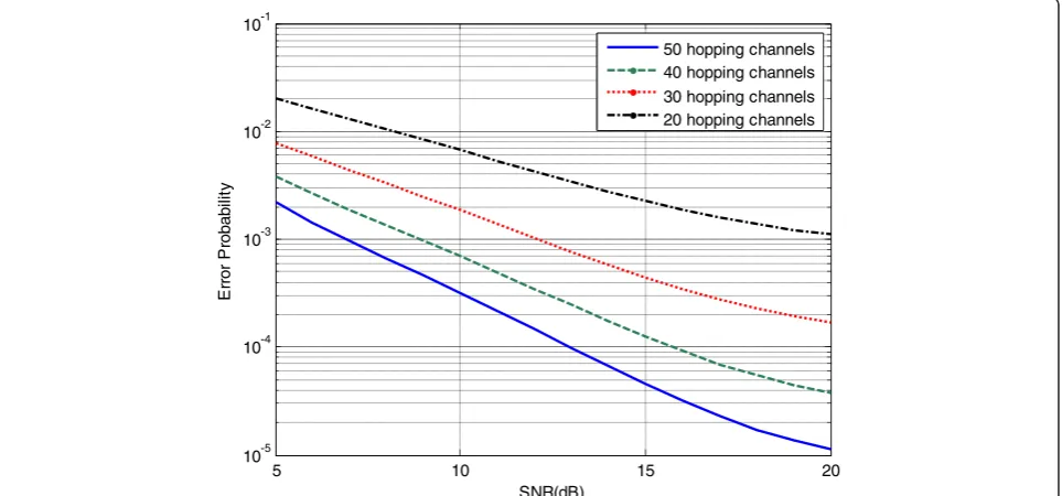
50 hopping channels 40 hopping channels
30 hopping channels 20 hopping channels
performance of the DS/FFH system is superior to that of the DS/SFH system (represented by the 1 hop/bit case). Also, notice the high improvement in performance at higher SNRs when increasing the number of hops per bit. This reveals the effectiveness of the proposed technique at high SNRs.
Figure 12 demonstrates the DS/FFH performance for dif-ferent numbers of available hopping channels. Increasing the number of hopping channels reduces the likelihood of
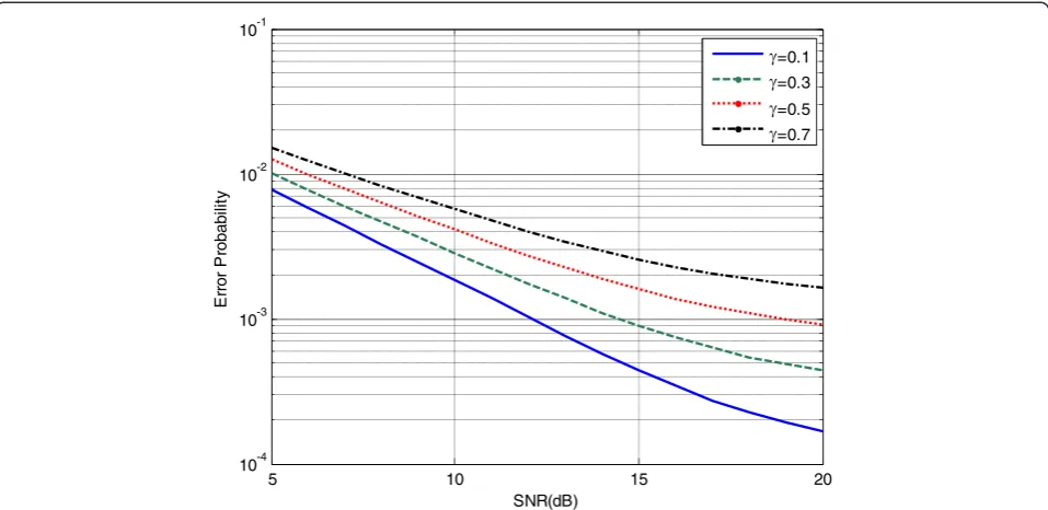
hits from other users using the same spreading PN-code and, therefore, enhances the performance. Figure 13 demon-strates the DS/FFH performance over varying degrees of Rician fading in the channels. You can observe how the per-formance deteriorates with increasing the fading component in the Rician channel represented by the parameterγ.
Figure 14 demonstrates the DS/FFH performance com-pared with the other SS systems that include DS, SFH, FFH, DS/SFH, and DS/FFH. It can be observed that the hybrid
5 10 15 20
10-4 10-3 10-2 10-1
SNR(dB)
E
rr
o
r
P
robabi
lit
y
=0.1
=0.3
=0.5
=0.7
Figure 13Performance of a hybrid DS/FFH system.Effect of different Rician fading channel parameters.
0 1 2 3 4 5 6 7 8 9 10
10-7
10-6
10-5
10-4
10-3
10-2
10-1
100
SNR
BER
BPSK
DS
SFH
FFH Hybrid DS/SFH
Hybrid DS/FFH
DS/FFH system outperforms the other SS systems. The hy-brid DS/FFH system is preferred over the other systems be-cause of its unique advantages, including the better spreading properties gained by frequency hopping and better multipath rejection via the direct-sequence modulation component.
The presented results demonstrate the effectiveness of the proposed hybrid DS/FFH scheme under severe channel con-ditions and, therefore, indicate that there is a high potential for employing it in complex smart grid communications.
7.2Optimizing hybrid DS/FFT system performance
We now provide numerical examples to illustrate the results derived in Section 5. For convenience, we only test the ne-cessary conditions that apply to the MLS code. We compute the solutions of the first-order necessary conditions (27) to (31) and impose the integer constraints. Then, the upper bound of the BER, PE, is plotted for different MLS code lengthsNusing (14) and (11) to verify the results computed from the derived first-order necessary conditions.
7 15 31 63 127 255 511 1023
10-4 10-3 10-2 10-1
PN-Code Length (N)
BER
K
1= 2600 Wb
K1= 3600 Wb
Figure 15BER versus DS PN-code lengthN.
The parameters of the reference hybrid DS/FFH system model considered is the same as described in the previous section (K= 100; JNR = 13 dB; γ= 0.1; and λ= 10.8), in addition to a signal-to-noise ratio (SNR) of 20 dB; finally, the portion of the channel partially corrupted isq¼WpJ=
NWb
ð Þ ¼30=N. Note that the parameters M, N, W, L
need to be computed for assessing the optimal perform-ance. From the previous analysis, the number of hops per bit is chosen asL= (1/K3Wb) = 5.
First, we choose K1= 2600Wb and K2= 0.2. Then, by
applying (27) to (31), we obtainN= 42. Because of the in-teger power-of-two constraint of N (N= 2n−1), it is rounded to the nearest two integers, 31 and 63. Then by applying (30) and (31) for each integer ofNand compar-ing the correspondcompar-ing BER of both integers, we see that
N= 31,M= 83, andW= 17 results in a smaller BER. The upper bound of the BER in (14) for different PN-code lengths,N, is demonstrated in Figure 15, in which we can now observe that atN= 31, the BER reaches its minimum. This coincides with the result from the first-order neces-sary conditions.
Now, we consider K1= 3600 Wb, with K2 unaltered.
Through a similar procedure, we obtain N= 48.3. After roundingNto 31 and 63, it can found thatN= 63,M= 57, andW= 11 results in smaller BER values. Figure 15 dem-onstrates the upper bound of the BER for different PN-code lengths,N, for this scenario. It can now be observed that the BER reaches its minimum at N= 63, which also coincides with the result from our analysis.
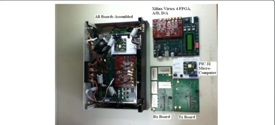
7.3 Experimental evaluations
Four bi-directional hybrid DS/FFH radio transceivers have been built in our lab and have performed well. The hard-ware prototype is shown in Figure 16. The sensitivity for the units is−110 dBm to produce an approximately 80% success rate at the packet level. This is 5 dB less sensitive than theoretically possible, but it is expected that the de-tection algorithms in the SDR could be significantly im-proved for better overall sensitivity. Also, the radios demonstrated a bit error rate of less than 10−6.
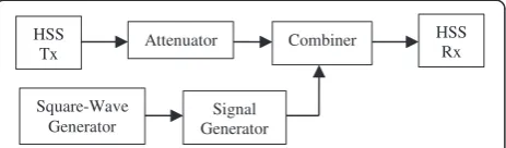
The jamming performance of the system was mea-sured directly with laboratory equipment. The testing method used for the HSS evaluation is shown in Figure 17. The square-wave generator is used at 20 kHz to modulate the signal generator at 100% AM modulation. The test procedure consists of initially transmitting data from the transmitter to the receiver with the signal generator turned off and the attenuator adjusted such that the re-ceiver is operating at an 80% success rate. The attenuator is then reduced 20 dB so the system has a 20-dB margin. Then the signal generator is turned on and ramped up in HSS
Tx Combiner
Signal Generator Square-Wave
Generator
Attenuator HSS
Rx
Figure 17Experimental setup for testing hybrid DS/FFH jamming resistance.
900 905 910 915 920 925 930
0 10 20 30 40 50 60 70 80
Frequency (MHz)
Jamming to Received Power Ratio(dB)
Without BPF
With BPF
power until the receiver has degraded to an 80% success rate. The difference in power between the signal generator (jamming) and the transmitter and attenuator combin-ation (at the 20-dB margin point) is then recorded. This is repeated for signal generator frequencies from 902 to 928 MHz. Versions of the test are performed with and without the AM modulation. This stresses the radio by exposing
clipping and other nonlinear effects that are expected in the A/D converter, SDR arithmetic, and analog front-end components.
The first test involved operating the HSS with the hop-ping feature turned off, so that the filtering capability of the SDR could be measured independently from the hopping benefits. In this test, the intermediate frequency
900 905 910 915 920 925 930
-10 0 10 20 30 40 50 60 70 80
Frequency (MHz)
Jamming to Received Power Ratio(dB)
AM Modulated Jamming
CW Unmodulated Jamming
Figure 19The hybrid DS/FFH prototype performance while the frequency hopping feature is disabled and in the presence of jamming.
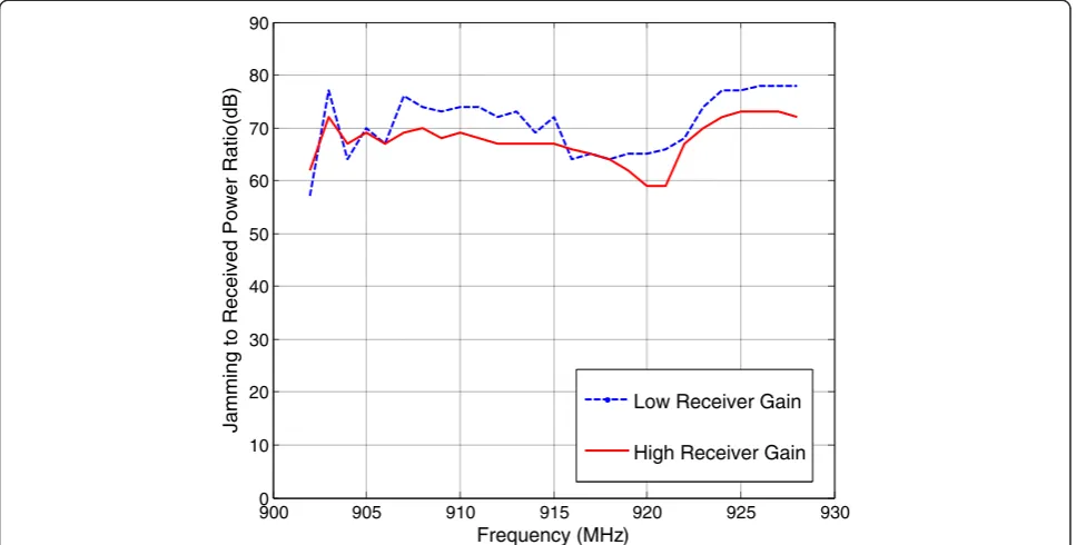
900 905 910 915 920 925 930
0 10 20 30 40 50 60 70 80 90
Frequency (MHz)
Jamming to Received Power Ratio(dB)
Low Receiver Gain
High Receiver Gain
was always 12.5 MHz, which also allowed us to insert an analog 12.5 MHz, 3-pole bandpass filter (BPF) in line. This filter lets us operate the radio as a standard analog radio and allows us to do a direct selectivity comparison between the analog and SDR approaches. This compari-son was made with the generator AM modulation turned off. The net results are shown in Figure 18. From the fil-tered version of the results, we still see the dynamic range limitations of the analog components ahead of the filter, which include the front-end amplifiers, surface acoustic wave (SAW) bandpass filters, and first mixer. Figure 19 demonstrates the effect of AM modulation on the jam-ming signal. Peak values of the jammer signal are used for the comparison. In general, the modulation makes the radio 10 dB more susceptible to jamming.
The main test for HSS is to show that its FH feature will make the system jam-resistant at all jamming frequencies. Experiments showed that the hopping frequencies have to be judiciously chosen such that within a redundant triplet, no two of the three frequencies would be near each other, since this would let a single jammer jam both frequencies. Therefore, the pattern could not be truly random but would need somewhat of a trend. Figure 20 shows the hy-brid DS/FFH jamming susceptibility versus frequency. Two receiver gain versions of the HSS were evaluated in this scenario. The difference in gain between the low-gain and high-gain version is 5 dB. Eventually, an automatic adjustment will be developed to choose the best value for a particular environment. It is noticed in Figure 20 that the smaller signal has less distortion and is able to better reject the undesired jamming signal at almost all frequencies.
8 Conclusion
In this paper, the performance of a hybrid DS/FFH sys-tem over Rician fading channels was considered. We de-rived the average BER for a hybrid DS/FFH system that includes the effects from wide- and partial-band jam-ming, multi-user interference, and/or varying degrees of Rician fading. Numerical results exploring the param-eter space of the HSS system have also been presented to demonstrate its effectiveness under different condi-tions and scenarios. We have also demonstrated a novel non-convex optimization technique that minimizes the bit-error probability of a hybrid DS/FFH communica-tion system under multiple constraints. By employing the Karush-Kuhn-Tucker conditions, the process solves for the optimal system design parameters. In addition, a hardware FPGA-based hybrid DS/FFH prototype was implemented successfully and optimized for a typical smart grid utility application. Experimental results indi-cate that high resistance of hybrid DS/FFH systems to other jamming and interference signals allows the possi-bility of intentionally operating several HSS radios in
the band simultaneously. For smart grid applications, this would enable a base station to service several cli-ents at the same time, provided the system arranged for different clients to use different hop patterns and DS codes, and possibly even coordinated transmission time windows. The use of hybrid DS/FFH waveform in wire-less networks as employed in the smart grid is recom-mended, as it offers superior resistance to jamming attacks and improves the reliability of transmission compared to existing SS techniques like DS, FH, and hybrid DS/SFH systems.
Competing interests
The authors declare that they have no competing interests.
Authors’contributions
MO carried out the hybrid DS/FFH system performance evaluation studies, conducted the computer simulations that provided numerical results, participated in deriving the analytical expressions and conducting experimental evaluations, and drafted the manuscript. XM derived the analytical expressions for evaluating and optimizing the performance and helped in drafting the manuscript. SK implemented the hybrid DS/FFH radio transceiver and evaluated its performance experimentally. TK shaped the main idea of the study and participated in its design, development, and coordination. SS conceived of the study and participated in investigating and enhancing its security performance. SD guided the analytical derivations and analysis. All authors read and approved the final manuscript.
Acknowledgment
This manuscript has been authored by UT-Battelle, LLC under Contract No. DE-AC05-00OR22725 with the U.S. Department of Energy. The United States Government retains and the publisher, by accepting the article for publication, acknowledges that the United States Government retains a non-exclusive, paid-up, irrevocable, world-wide license to publish or reproduce the published form of this manuscript, or allow others to do so, for United States Government purposes. The Department of Energy will provide public access to these results of federally sponsored research in accordance with the DOE Public Access Plan. In addition, this work has been partially supported by NSF grant CMMI-1334094.
Author details
1Computational Sciences and Engineering Division, Oak Ridge National Laboratory, P.O. Box 2008, MS 6085, Oak Ridge, TN 37831, USA.2Department of Electrical Engineering and Computer Science, University of Tennessee, 1520 Middle Drive, Knoxville, TN 37996, USA.3Department of Electrical Engineering and Computer Science, Masdar Institute of Science and Technology, Masdar City, Abu Dhabi, UAE.
Received: 30 October 2014 Accepted: 17 February 2015
References
1. MP Pursley, Direct sequence spread spectrum communications for multipath channels. IEEE Trans Microwave Theory Tech50(3), 653–661 (2002)
2. EA Geraniotis, Noncoherent hybrid DS-SFH spread-spectrum multiple-access communications. IEEE Trans Commun34(9), 862–872 (1986)
3. J Zhang, KC Teh, KH Li, Error probability analysis of FFH/MFSK receivers over frequency-selective Rician-fading channels with partial band noise jamming. IEEE Trans Commun57(10), 2880–2885 (2009)
4. JH Lee, BS Yu, SC Lee, Probability of error for a hybrid spread spectrum system under tone jamming, inProc. of the IEEE Military Communications Conference (MILCOM’90), 1990, pp. 410–414
6. Y Fu, H Leung, Narrow-band interference cancellation in spread-spectrum communication systems using chaos. IEEE Trans Circuit Syst I48(7), 847–858 (2001)
7. Security Profile for Advanced Metering Infrastructure (AMI), The Advanced Security Acceleration Project (ASAP-SG), Version 2.0, Jun. 2010. Available at: http:// osgug.ucaiug.org/utilisec/amisec/Shared%20Documents/AMI%20Security% 20Profile%20(ASAP-SG)/AMI%20Security%20Profile%20-%20v2_0.pdf
8. Analog Devices, A Technical Tutorial on Digital Signal Synthesis, Technical Report, 1999. Available at: http://www.analog.com/media/cn/training-seminars/tutorials/ 450968421DDS_Tutorial_rev12-2-99.pdf
9. PA Bello, Characterization of randomly time-variant linear channels. IEEE Trans Commun Syst11, 360–393 (1963)
10. DE Borth, MB Pursley, Analysis of direct-sequence spread-spectrum multiple access communication over Rician fading channels. IEEE Trans Commun27
(10), 1566–1577 (1979)
11. EA Geraniotis, MB Pursley, Error probabilities for slow-frequency-hopped spread-spectrum multiple-access communications over fading channels. IEEE Trans Commun30(5), 996–1010 (1982)
12. EA Geraniotis, Coherent hybrid DS-SFH spread-spectrum multiple-access communications. IEEE Trans Commun3(5), 695–705 (1985)
13. B Solaiman, A Glavieux, A Hillion, Error probability of fast frequency hopping spread spectrum with BFSK modulation in selective Rayleigh and selective Rician fading channels. IEEE Trans Commun38(2), 233–240 (1990) 14. C Park, JH Lee, Probability of error for a hybrid DS/SFH spread spectrum system
over a Rician fading channel in the presence of multiple-tone jamming, inProc. of the IEEE Second International Symposium on Spread Spectrum Techniques and Applications (ISSSTA’92), 1992, pp. 123–126
15. CC Chen, K Yao, K Umeno, E Biglieri, Design of spread-spectrum sequences using chaotic dynamical systems and ergodic theory. IEEE Trans Circuit Syst I48(9), 1110–1114 (2001)
16. MM Olama, SF Smith, PT Kuruganti, X Ma, Performance study of hybrid DS/FFH spread-spectrum systems in the presence of frequency-selective fading and multiple-access interference, inProc. of the IEEE International Communications Quality and Reliability (CQR) Conference, 2012
17. X Ma, MM Olama, T Kuruganti, SF Smith, SM Djouadi, Determining system parameters for optimal performance of hybrid DS/FFH spread-spectrum, in
Proc. of the IEEE Military Communication Conference (MILCOM'12), 2012, pp. 1888–1893
18. M Killough, MM Olama, T Kuruganti, SF Smith, FPGA-based implementation of a hybrid DS/FFH spread-spectrum transceiver, inProc. of the World Congress in Computer Science, Computer Engineering, and Applied Computing
(WORLDCOMP'13), 2013
19. MM Olama, SM Killough, T Kuruganti, TE Carroll, Design, implementation, and evaluation of a hybrid DS/FFH spread-spectrum radio transceiver, in
Proc. of the IEEE Military Communication Conference (MILCOM’14), 2014 20. DP Bertsekas,Nonlinear Programming, 3rd edn. (Athena Scientific, Belmont,
Massachusetts, 1999)
21. M Schwartz, WR Bennett, S Stein,Communication Systems and Techniques
(McGraw-Hill, New York, 1966)
22. HL Van Trees,Detection, Estimation, and Modulation Theory, Part 111(Wiley, New York, 1971)
23. RS Kennedy,Fading Dispersive Communication Channels(Wiley, New York, 1969)
24. MB Pursley, Performance evaluation for phase coded spread spectrum multiple-access communication-Part I: system analysis. IEEE Trans Comm25, 759–799 (1977)
25. TS Rappaport,Wireless Communications: Principles and Practice(Prentice Hall, New Jersey, 1996)
26. DV Sarwate, An upper bound on the aperiodic autocorrelation function for a maximal-length sequence. IEEE Trans Inf Theory30(4), 685–687 (1984) 27. D Taylor, Introduction to synchronous communications, a classic paper by. J
Costas Proc IEEE90(8), 1459–1460 (2002)
28. Y-R Tsai, M-ary Spreading-Code-Phase-Shift-Keying modulation for DSSS multiple access systems. IEEE Trans Comm57(11), 3220–3224 (2009)
Submit your manuscript to a
journal and benefi t from:
7Convenient online submission
7Rigorous peer review
7Immediate publication on acceptance
7Open access: articles freely available online 7High visibility within the fi eld
7Retaining the copyright to your article