R E S E A R C H
Open Access
Interference coordination for millimeter
wave communications in 5G networks for
performance optimization
Jiao Wang
1*, Jay Weitzen
1, Oguz Bayat
2, Volkan Sevindik
1and Mingzhe Li
3Abstract
To address the increasing data rate demands for future wireless networks, a dense deployment of base stations or access points is the most promising approach; however, doing so may cause high intercell interference (ICI). Numerous interference coordination (IC) approaches have been proposed to reduce ICI. Conducting 5G communication on millimeter wave (mmWave) bands is more complex because of its higher propagation losses and greater attenuation variance, all of which depend on environment change. Massive antenna arrays with beamforming techniques can be used to overcome high propagation loss, reduce interference, deliver performance gains of coordination without a high overhead, and deliver high network capacity with multiplex transmitters. The central challenge of a massive antenna array that uses beamforming techniques is coordinating the users and beams for each transmitter within a large network. To address this challenge, we propose a novel two-level beamforming coordination approach that partitions a large network into clusters. At the intracluster level, this approach performs intracluster coordination similar to the user selection algorithms in a multiuser multiple input and multiple output (MU-MIMO); doing this maximizes the utility function or minimizes the signal-to-interference-plus-noise ratio (SINR) function within a cluster. A dynamic time domain IC approach is employed at the intercluster level, collecting interference information for cluster-edge user equipment (UE) and allocating the UE dynamically among the clusters to reduce the intercluster interference for a switched-beam system (SBS). Simulation results show that the proposed two-level IC approach achieves a higher edge user performance or cell capacity than with the current uncoordinated/coordinated approaches.
Keywords:5G, Interference coordination, Massive MIMO, Beamforming, MU-MIMO
1 Introduction
The continued evolution of cellular networks has come with increased expectations for higher data rates. The tremendous growth of data demand in the upcoming years will inevitably lead to issues between capacity requirements and spectrum shortage. A feasible remedy is required to increase the spectrum reuse factor by using dense deployment in conjunction with improved spectral efficiency. Operators tend to allocate the same frequency band to densely deployed neighbor cells, that is, with a frequency reuse factor of one or a universal frequency re-use (UFR) factor [1] to save spectrum. This deployment creates high interference among users who use the same
frequency in neighboring cells, particularly users who are located close to the cell’s edge.
The basic static interference coordination (IC) ap-proach uses frequency planning [2], and there are three major static IC approaches: conventional fractional fre-quency reuse (FFR), partial frefre-quency reuse (PFR), and soft frequency reuse (SFR). FFR splits the spectrum into segments and distributes them between neighbor cells
[3, 4]. PFR splits the spectrum into two segments,
where the first segment uses an FFR approach with a frequency reuse factor larger than one that is allocated to the cell’s edge region; another segment uses the FFR approach with a frequency reuse factor equal to one that is allocated to the cell’s center region [5, 6]. SFR splits the frequency band into N segments and uses a dedicated segment (or prioritized segment) for edge user equipment (UE) with higher transmit power [7– * Correspondence:[email protected]
1Department of Electrical and Computer Engineering, University of
Massachusetts, Lowell, MA 01854, USA
Full list of author information is available at the end of the article
11]. Other segments (nonprioritized segments) are available for central UE with lower transmit power. The prioritized segments of neighbor cells are orthogonal in their frequency to reduce interference among the cell edge UE.
The 3rd Generation Partnership Project (3GPP) LTE released 10 enhanced IC (eIC) approaches, including carrier aggregation-based IC (CBIC) [12, 13]. Here, CBIC uses multiple component carriers (CCs): every cell uses one primary component carrier (PCC) for the call setup, control channel transmission, and so forth. CBIC can also dynamically allocate additional CCs, called secondary component carriers (SCCs), according to the traffic load. The transmit power varies among the CCs, and PCC/SCCs are selected to minimize interference among neighboring cells.
In addition to frequency domain IC (FIC) approaches, there are also time domain IC (TIC) approaches. Here, the almost blank subframe (ABS) approach is a TIC approach that allows a spectrum to be time shared [14, 15]. The “aggressor” cells (cells causing interference) will mute cer-tain subframes so that the victim cells (cells being interfered with) can serve their UE in those subframes. These sub-frames are“almost blank”because the aggressor continues to transmit broadcast signals over the subframes.
One way to dynamically share time/frequency resources is through using graph-based approaches or utility-based approaches. Graph-based interference coordination (GIC) mitigates intercell interference (ICI) by building and parti-tioning interference graphs [16–18]; an interference graph is a graph whose nodes represent the UE and whose edges represent interference among the UE. Connected UE will try to avoid using the same time/frequency resources to achieve a minimum SINR. Utility-based interference coordination (UIC) is designed to maximize network util-ity [19–21]. At sectors, the approach calculates utilities for different interference scenarios with a different number of interferers where the utility is defined to favor the UE at the cell’s edge. At a central unit, the approach processes resource allocation requests from all sectors and resolves conflicts based on the utilities that have been calculated.
Future 5G cellular systems need to support multigiga-bits per second (Gbps) cell capacity and tens of megamultigiga-bits per second (Mbps) cell edge throughput. Current cellular spectrums below 5 GHz are constrained by the available bandwidth. Millimeter wave (mmWave) bands (30–300 GHz) offer a solution because there are vast amounts of spectrum available in mmWave bands [22]. The small wavelengths allow for smaller massive mul-tiple input and mulmul-tiple output (MIMO) antenna arrays, making them suitable for implementation on both a base station (BTS) and UE. By using massive MIMO antenna arrays, significant beamforming gains can help to over-come the high propagation loss over the mmWave
frequency, and the spatial reuse can reduce the interfer-ence found with intra- and intercells. Massive MIMO antenna array systems in mmWave bands are ideally suitable for high-capacity transmission and are consid-ered an important part of 5G.
To use massive MIMO antenna arrays in mmWave bands, two cooperative schemes—coordinated beam-forming (CBF) and coordinated multiuser MIMO (MU-MIMO)—have been proposed.
In the CBF scheme, data are only available at a serving cell; however, for the channel-state information (CSI) scheme, the sharing levels can be defined as follows: full CSI sharing, partial CSI sharing, and no CSI sharing [23]. With full CSI sharing, the problem can be formu-lated as an optimization problem for beamforming weight vector calculations among the coordinated cells [24–26]. With partial CSI sharing, when inter-base-sta-tion communicainter-base-sta-tion is limited, the interfering BTS can perform nulling to cancel the ICI and can conduct user selection and beamformer design in a cooperative fash-ion to select users with the worst parallel interfering channels to the victim to decrease the ICI caused by all streams [23, 27]. For the no CSI sharing scenario, ap-proaches have been proposed to maximize the ratio between the signal strength of served users and the interference caused to other users; this is called the signal-leakage-plus-noise ratio (SLNR) [28, 29]. Here, a lightweight CBF approach is precoding matrix indicator (PMI) coordination, in which each UE transmits either “restriction PMI” or “recommendation PMI” to its serv-ing cell. Then, the neighborserv-ing eNB can either use the recommended PMI or avoid the restricted PMI through coordination among the eNBs [30].
In a coordinated MU-MIMO scheme, nearby cells form a virtual single transmitter and jointly perform MU-MIMO transmission, thus eliminating ICI and achieving the best possible performance. However, this type of coordination requires a precise time and fre-quency synchronization among the coordinated cells [31]. To address this practical challenge, recent work has proposed using hybrid digital/analog beamforming to take advantage of numerous antennas without using the same number of RF chains. A hybrid digital/analog beamforming approach has been proposed to reduce the ICI without a more precise time and frequency syn-chronization among the coordinated cells [32].
control the relative phase between the antenna elements and their amplitude distribution. In this way, specific beam patterns can be produced, directing the main lobe toward the desired MS and the nulls toward the interfering signals [34]. One reason to use an SBS system is its low cost because fully reconfigurable front ends are too expensive to be implemented in a commercial wire-less network.
Fixed wireless access (FWA) refers to the last-mile delivery of Internet access to residential or business customers who are using wireless network technology rather than fixed lines. In the upcoming 5G state, fixed wireless access is being considered an early use case or proof-of-concept of the new technology. In essence, 5G is a potential complement or replacement to fiber-to-the-home (FTTH) broadband wireline access, which is considered expensive to deploy.
1.1 Contribution
In the current research, we propose a novel two-level coordination approach, referred to as the intracluster and intercluster levels, for SBS and that will be targeted at FWA use cases. At the intracluster level, the pro-posed approach performs intracluster coordination similar to the user selection algorithms in the context of multiuser MU-MIMO, finding a way to maximize a utility function or minimize the SINR function within a cluster. At the intercluster level, the proposed method employs a time domain IC approach, collects interfer-ence information for cluster-edge UE, and allocates UE dynamically among clusters to reduce intercluster inter-ference. The main contributions of the current paper are as follows:
Our research improves the GIC approaches proposed in [17,18] and the UIC approaches proposed in [19,20], turning them into a massive MIMO domain, formulating these schemes into a common framework, and investigating cell capacity and the cell edge performance tradeoff of these schemes.
A main challenge of the massive MIMO IC
approaches is to coordinate the users and beams for all transmitters within a large network. Our research proposes a two-level approach to reduce complexity. At the intracluster level, our research improves the approaches proposed in [31] for an SBS, proposes a spatial-time domain resource allocation methodology to resolve transmission slot allocation, employs UE selection and beam selection jointly.
One challenge of IC approaches is to reduce interference while lowering capacity loss. Our research, at the intercluster level, investigates both distributed and centralized IC approaches. The
centralized IC approach employs a dynamic time domain IC approach that includes a built-up intercluster interference graph, graph partitioning into groups, and exhaustive searching within each group for optimal resource allocation.
The proposed approach can reduce intercluster interference without significant capacity loss.
The remainder of the present paper is organized as follows: Section 2 formulates the problem, Section 3 describes the proposed approach, Section 4 describes the simulation methodology, Section 5 presents the simulation results, Section 6 shows the complexity analyses, and Section7concludes the paper.
2 Problem description
In the current research, we concentrate on TIC ap-proaches. We first modify the UIC approach proposed in [19–21] for SBSs. A general resource allocation problem can be formulated in the following way: first, assuming the mobile network consists of Ncells andUusers, it can be denoted asN= {1, …,N},U= {1, …,U}, respectively; if as-suming the network is an SBS system and thatMbeams in each sector cover the coverage area, it can be denoted as M= {1, …,M}; a scheduling period ofTtransmission time intervals (TTIs) can be denoted asT= {1, …,T};Iu,n,m(t) is defined as the user resource allocation indicator, where values of 1 and 0 indicate the following: ifIu,n,m(t) = 1, the m∈M}; then, we have the following optimization problem:
adjusted to favor UE at the cell’s edge. In the current research, we setwu= 1; ru, n, mis the data rate achieved
ru;n;mðp;IÞ ¼Wlog2½1þSINRu;n;mðp;IÞ ð2Þ
whereWis the bandwidth of the carrier, andSINRu, n,m is the received SINR for user ufrom cell non beam m, which is given as follows:
SINRu;n;mðp;IÞ ¼P gu;npu;n;m
l∈N;k∈M;ðl≠n&k≠mÞIu;l;kgu;l pu;l;kþσu ð3Þ
wheregu,nis the channel gain between cellnand useru;
σu
is the thermal noise. We define the max number of beams that can be allocated concurrently per cell asMmax, andPn, maxis the maximum transmit power for celln.
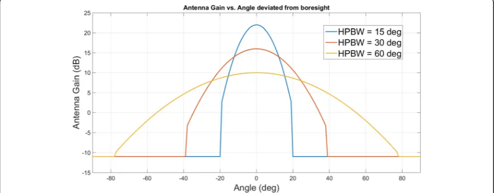
For simplicity, the current research uses basic and switched directional antennas and assumes an SBS sys-tem is being used. The cell side has an antenna array with multiple antenna elements, while the gain pattern of these elements shows an asymmetric gain that is be-ing referenced from 3GPP TSG RAN WG1 [37, 39]. Basic antennas exhibit the modeled behavior of a decay-ing gain at the main lobe or direction of transmission, and these antennas take the averaged gain value outside at the sidelobe. A switched antenna can only transmit in a discrete direction in which the values are not continu-ous [35]. The width of the main lobe is defined as the half power beam width (HPBW)θB, or the point where the antenna gain falls by 3 dB from the boresight. When beamforming with more antenna elements, the HPBW will become narrower. Figure1shows the pattern of the antenna withθBof 15°, 30°, and 60°.
Equation (4) shows an antenna pattern in decibels [35]. The signal gain is a function of the deviated direction ∅.
Note here that the point deviating from the boresight by an angle value ofθB/2 reduces the gain by 3 dB.
Gtð Þ ¼∅ G0;dB−12
∅
θB 2
∅
j j≤1:3θB
Gℕ;dBj j∅ >1:3θB 8
<
: ð4Þ
The antenna achieves its maximum gain G0, dB when the receiver is in the transmission direction. A gain out-side the main lobe with a derivation of 1.3 ×θBbecomes a gain of Gℕ, dB, with averaged gain values at the
side-lobe of the real antennas.
Using the above basic and switched directional anten-nas, we get the following:
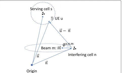
pu;n;m¼jpu;n;mj Gtð∅u;n;mÞ ð5Þ
where |pu, n, m| is the max power transmitted by cell n with beam m to user u at time t. ∅ can be calculated with the following equation:
∅u;n;m¼ cos−1 !u−!n
∙!m u
!−!n
!m ð6Þ
where!u;!n, and !m are the location vectors of the user, cell, and direction vector of the beam boresight. The channel gain can be calculated as follows:
gu;n¼g!u−!n ð7Þ
where g is the general path loss function depending on the distance. Figure 2 shows the power transmitted be-tween the cells and UE.
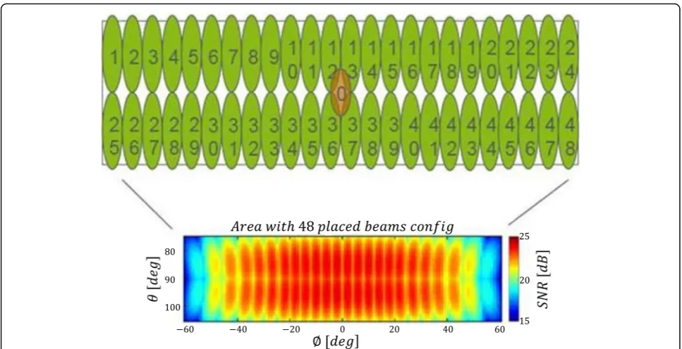
In SBSs, each user chooses only one beam to trans-mit and/or receive at one time, which is referred to as
serving beam in the Verizon 5G physical layer proce-dures [40]. Figure 3 shows the TX pattern of a commercial 5G antenna. The 120° sector is covered by 48 beams, each of which has a beam ID. The cell keeps transmitting beam reference signals (BRS) for every BRS transmission period. When UE enters the cover-age area of the cell, it detects the strongest beam ID by measuring the beam reference signals received power (BRSRP) and locks in on it for data transition. The strongest beam for user u from cell ncan be de-fined asm~u;n.
To consider how this would work in reality, we can assume a constant transmit power p0 for all cells, and
if multiple beams are transmitted simultaneously, the power will be evenly distributed among the beams, as follows:
pu;n;m¼P p0
u1∈Un;m1∈MIu1;n;m1
Gtð∅u;n;mÞ ð8Þ
According to Eq. (8),pu,n,mis a function ofIu,n,m, the power variable in problem P can be removed, and the problem will be simplified as a function ofI,!u;!n, and!m. With the above simplification, the problem can be re-written as follows:
Problem P1:
MaximizeX
t∈T X
n∈N X
u∈Un wu
X
m∈M
ru;n;mð ÞI ð9Þ
Over:I Subject to:
Iu;n;mð Þ ¼t 1m¼m~
u;n
0 Else
ð10Þ
X
u∈Un
Iu;n;mð Þ≤t Mmax∀n∈N;t∈T ð11Þ
where
ru;n;mð Þ ¼I Wlog2½1þSINRu;n;mð ÞI
where
SINRu;n;mð Þ ¼I P gu;npu;n;m
l∈N;k∈M;ðl≠nk≠mÞIu;l;kgu;lpu;l;kþσu
gu,nandpu,n,mare defined in (4)–(8);∅u,n,mis defined in Eq. (6), andθBis the HPBW; (10) is a constraint when
attempting to define the UE–beam paring relationship, in which each user is assigned only to the strongest beam it detects, and this only occurs once during one scheduling period ofTTTIs.
Problem P1 maximizes the network capacity, but it can-not guarantee the minimum edge performance. To guar-antee improved edge performance, GIC approaches have been proposed to partition all UE within the network into groups of UE and to allocate time/frequency resources to the UE groups, where the UE within a group would have an interference level less than a predefined threshold. The problem can be reformulated as follows:
Problem P2:
MaximizeX
n∈N X
u∈Un
Iu;nð Þ∀t t∈T
Over:I Subject to:
SINRu;nð ÞI >SINRThreshold∀n∈N;u∈U ð12Þ
where SINRThreshold is a predefined SINR threshold, not-ing that the beam variablemhas been removed from SINR because each user u can be mapped to only one beam. SINRu,n(I) is defined in the same way as in P1 by using Eqs. (3)–(8).
P1 or P2 each solve the user resource allocation indica-tor, I, for all UE within the network and at any transition time. Constraints are used to restrict the selection of I. P1, or the UIC approach, attempts to maximize network cap-acity, and it improves edge performance also when UE that is experiencing less interference is assigned together for
maximizing network capacity, particularly with the help of beamforming. However, P1 cannot guarantee minimum edge performance. P2, or the GIC approach, does guaran-tee minimum edge performance by restricting I to satisfy a predefined SINR threshold; however, in doing so, it sacri-fices network capacity.
3 Two-level IC approach
For large networks that have scalability considerations, cells are grouped into coordination clusters to make the front haul communication overhead more affordable. For P1 and P2, the user resource allocation indicator,I, is cal-culated within each cluster, not for the whole network; this creates an intercluster interference problem, that is, the ICI within a cluster (intracluster interference) has been minimized; however, significant interference still exists be-tween clusters (intercluster interference) because of less coordination between the clusters.
In this section, we present our proposed two-level IC approach. Here, P1 and P2 are nonconvex problems, and optimal solutions are not yet feasible in practice. A greedy algorithm that yields locally optimal solutions in a reason-able time can be used as a low overhead heuristic solution at the intracluster level. More complex heuristic solutions can be used at the intercluster level for better performance.
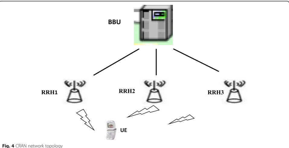
(i.e., using a common public radio interface [CPRI] stand-ard to reduce latency) and coordinate the interference among the RRHs within the network. The baseband func-tional split leaves the media access control (MAC) layer scheduling to the BBU and the physical layer functionality to the RRH. The diagram also shows that when an UE connects to the RRH1 and detects the RRH2 and RRH3 as significant interferers.
3.1 Network clustering
We use a clustering approach in which each UE (victim) in a sector (serving sector) calculates the possible interference that it may experience from a nearby sector. The possible interference is calculated based on all the UE in a nearby sector, their allocated beam, and the beam’s direction. The fixed transmit power is assumed. Path loss to the victim is calculated using Eqs. (6)–(8). The possible interference of all the victims in a serving sector is averaged, and the interfer-ence defines the relationship between the serving sector and the nearby sector. With a higher interference, the two sec-tors are more likely to be grouped into a cluster; the cluster starts with one random selected sector, and a new sector is added if it has the highest average possible interference level with all the sectors that are already in the cluster. The clus-ter grows until it reaches a predefined maximum clusclus-ter size Cmax. The clustering algorithm only needs to be run once
for a long period of time, that is, when there is a significant traffic change within the network.
3.2 Intracluster interference graph construction
An intracluster interference graph is built for all UE within a cluster by using the directed graph G= (N,V), whereN
nodes representNUE. TheVedges with different weights w represent the interference relationship between the UE. The direction is indicated by drawing an arrow fromA(the source node) toB(the destination node), meaning that ifB is scheduled, it will causewA,Binterference toA.
The interference graph is built statically using Eqs. (6)–(8) with a fixed transmit power. The interference between the UE is calculated dynamically during sched-uling and updated with different transmit powers when multiple UEs are scheduled simultaneously.
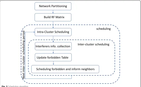
3.3 Scheduling algorithm 3.3.1 Intracluster scheduling
The network has now been partitioned into smaller clus-ters. Within each cluster, each cell can schedule up to Mmax UE per TTI. The first proposed approach is to use
an exhaustive searching algorithm to solve the user re-source allocation indicator I. However, even with a small cluster, the exhaustive searching algorithm is far too com-plex, that is, by consideringNcells in the cluster andUUE per cell, the complexity will beOðQNn¼1½PMmax
k¼1 CUkÞ.
Therefore, low overhead heuristic approaches must be developed to reduce the complexity. Greedy algorithms are straightforward and yield locally optimal solutions that have a reasonable complexity. Many approaches using the greedy strategy have been proposed to extract a multiplexing gain for the MU-MIMO problem, which is a subproblem of what we formulated in Section2. For the current research, we also use a greedy algorithm for intracluster scheduling.
For the intracluster scheduling, coordinated schedul-ing is performed within each cluster, and this is based
on the interference graph built in the previous step. The greedy algorithm starts with a randomly selected UE, and UEs that have lower interference are added accord-ing to the followaccord-ing criteria:
P1: Increased network utility defined in (9).
P2: Increased number of UEs assigned and that satisfy the constraint defined in (12).
The number of UEs is added until the above criteria are broken or the max number of users that can be assigned has been reached. The number of UEs will be partitioned into groups, and each group is assigned to one TTI. For any sector within the cluster, if one UE has been scheduled, it will not be scheduled in the following TTIs until all the UEs have been scheduled and the intracluster scheduling process restarts. The following pseudo-code shows the algorithm:
With intracluster scheduling, the intracluster interference is minimized because highly interfered UEs are scheduled to different TTIs. The UEs scheduled to the same TTI are either allocated to beams with a sufficient angle division or with enough distance between each other.
The intracluster scheduling period is defined as the time or number of TTIs that all UEs have been scheduled. Because of the dynamic characteristic of traffic, when UEs finish their traffic and are no longer active, they should be excluded dynamically from intracluster scheduling till the next intracluster scheduling period.
3.3.2 Intercluster scheduling
The UEs at the cluster edge may experience poor RF because there is no coordination between the clusters. The intercluster scheduling, which runs at every in-tercluster scheduling period, can be used to restrict all the UEs scheduled by the intracluster scheduling algorithm for each cluster. The intercluster scheduling period is defined as the time or number of TTIs that there is no significant channel and traffic change. We
assume an FWA application with slow varying
channel.
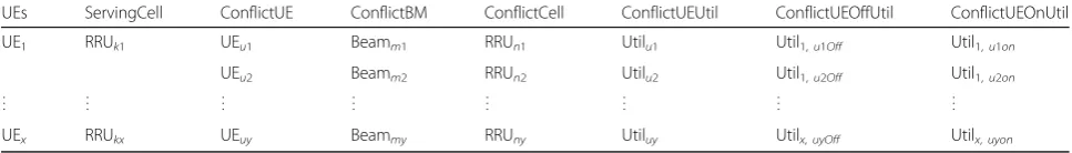
First, the cluster-edge UEs report to their serving cells a list of forbidden UEs in the neighboring clus-ters based on the channel measurements performed on the cells’ reference symbols and the multiple ver-sions of SINRs corresponding to the different interfer-ence scenarios. The forbidden UEs are the ones causing the most interference, and by removing some or all of them, the cluster-edge UEs can achieve a SINR higher than the predefined SINR threshold. The forbidden relationship table can be built at each cell, BBU, or central unit according to the proposed algo-rithms and then updated dynamically. Table 1 shows an example of a forbidden relationship table.
Three heuristic algorithms have been proposed for in-tercluster scheduling. The following pseudo-code shows an algorithm:
algorithm for P1: utility maximization. In the code, Util are the values reported in the forbidden relationship table, and offset is value in the range of 0 to 1 to control the interferers that need to be turned off.
Algorithms 2 and 3 are distributed IC algorithms and can be run on each cell/cluster to determine the UEs allocated among neighbor clusters and exchange the UEs that have a forbidden relationship between neighbor clusters using the × 2 interface. Figure 5 shows the scheduling algorithm.
The two proposed algorithms select the UEs from the outputs of intracluster scheduling, and after in-tercluster scheduling, less UEs will be scheduled, creating capacity loss compared with the approach when there is intracluster scheduling only. So, select-ing the UEs to reduce interference as much as pos-sible and keep capacity loss to a minimum is the problem. The next proposed algorithm is a central-ized IC algorithm; it starts from intercluster interfer-ence graph built up. A similar interferinterfer-ence graph as the intracluster interference graph introduced in paragraph B is built for each intercluster scheduling period: graph G’= (N′,V′), where N′ nodes represent N′ UE selected from the UEs scheduled during the intracluster scheduling phase, including cluster-edge
UE (UEs with lower SINR than a predefined
SINRThreshold) and their interferers. The V′ edges represent the most significant interference relationship betweenN′nodes. Figure6shows an example of an inter-cluster interference graph. The graph illustrates where the UE (b) have the most significant interferers (a). The direc-tion is indicated by drawing an arrow from (b) (the source node) to (a) (the destination node).
Step 2 comprises graph partitioning. The breadth-first search algorithm [41] has been used to partition the graph into groups, where each group is a set of nodes of the graph that interfere significantly with each other. The UEs that cause the highest interfer-ence to their neighbors are used as the distinguished nodes or heads of groups. The search starts by adding the head into a group and then recursively adding the source nodes of the existing nodes in the group until the group reaches a maximum size. The maximum size of a group is limited to a low value to avoid high computation complexity. Figure 6 shows an example of the groups.
In step 3, the algorithm exhaustively searches within each group for an optimal resource allocation solution to maximize network utility. For example, a group with five nodes has 32 permutations (where each node has two possible states: assigned or not assigned), each per-mutation corresponds to a utility, and the perper-mutation with a maximum utility will be selected.
After the central unit determines the UEs assigned among neighbor clusters, all clusters or cells within the network will be informed.
Table2summarizes the proposed algorithms.
4 Simulation methodology
To evaluate the proposed two-level IC approach, a network consisting of two tiers of sectored cells was simulated (hexagonal model for a 19-cell cellular network). The BSs are in the center of each cell, and each BS has three-directional antennas. The first an-tenna orientation always points north, and the other antenna orientations each deviate 120° clockwise from the previous one. Altogether, 57 sectors were simulated; however, only the center seven cells (21 sectors) were used for the performance evaluation. Table 1Forbidden relationship
UEs ServingCell ConflictUE ConflictBM ConflictCell ConflictUEUtil ConflictUEOffUtil ConflictUEOnUtil
UE1 RRUk1 UEu1 Beamm1 RRUn1 Utilu1 Util1,u1Off Util1,u1on
UEu2 Beamm2 RRUn2 Utilu2 Util1,u2Off Util1,u2on
⋮ ⋮ ⋮ ⋮ ⋮ ⋮ ⋮ ⋮
a
c
b
Fig. 6An intercluster interference graph
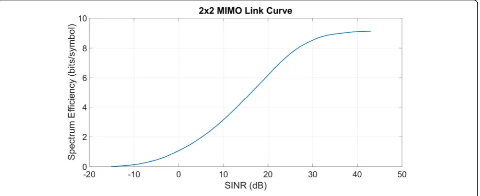
The Verizon LTE time division duplex (TDD) air interface physical layer structure was used [36]. Each radio frame has 10 ms of time and consists of one hundred 0.1 ms slots that are numbered from 0 to 99. A subframe is defined as two consecutive slots. The bandwidth is divided into resource blocks (RBs), and each RB uses a spectrum of 900 KHz, divided into twelve 75 KHz subcarriers. The LTE TDD subframe configuration 2 is used with a downlink (DL)/UL resource ratio of 0.75 to 0.25. Only the DL has been simulated, and a 2 × 2 MIMO closed-loop spatial multiplexing (CLSM) transmis-sion mode, 64 quadrature amplitude modulation (QAM), control format indicator (CFI) 1, and ex-tended pedestrian A (EPA) 5 Hz multipath model were used. Figure 7 shows the link curve. Table 3 summarizes the simulation set-up.
The 3GPP Urban Macro outdoor propagation loss model [37] was used. The line-of-sight (LOS) prob-abilities are defined in the following equation, where the height of each UE has been left out:
PLOS¼
1 d2D≤18m
18
d2Dþ
exp −d2D
63
1− 18
d2D
18m<d2D
8 < :
ð13Þ
where d2D is the 2D distance between the BS and UE.
Assuming a small intersite distance (ISD) of less than 1 km, the path loss is calculated using the following equations:
PLUMa−LOS¼32:4þ20 log10ðd2DÞ þ20 log10ð Þfc
PLUMa−NLOS¼ max PLUMa−LOS;PL0UMa−NLOS
where
PL0UMa−NLOS¼13:54þ39:08 log10ðd2DÞ
þ20 log10ð Þfc ð14Þ
5 Simulation results
Figures 7, 8, 9, 10, and 11summarize the performance of the proposed two-level IC approach compared with both the uncoordinated and coordinated MU-MIMO approaches. Table4summarizes all the approaches.
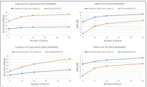
Figure8 compares the average sector throughput and the SINR at a 5% tail for the different IC approaches for a scenario with a max of four MU-MIMO users. The scenario simulates a cellular network with an ISD of 200 m; with 20 users per sector; with four, eight, 12, and 24 beams to cover the sector coverage area; with Table 2Proposed algorithms
Algorithms Intra-cluster target
Inter-cluster target
Pros and cons
DIC P2 P2 P2 High capacity loss, high edge performance
improvement, low complexity
DIC P1 P1 P1 Mid capacity loss, mid-edge performance
improvement, low complexity
CIC P1 P1 P1 Low capacity loss, mid-edge performance
improvement, high complexity
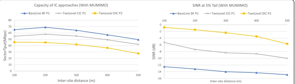
a max cluster size of three; and with P2 targeted as the performance criteria. The baseline approach has no interference coordination and is performed be-tween any neighbor sectors. The coordinated BF IC approach (BFIC) is a one-level IC approach with only intracluster scheduling. This is similar to the user selection algorithm in a MU-MIMO context that would schedule the UEs with large separation in the transmission angle. Our proposed two-level dis-tributed IC (DIC P2) approach, together with the BFIC approach, shows better edge performance than the baseline approach. The DIC P2 approach is about 4 dB better than the BFIC approach in edge performance and has almost the same capacity. Both the BFIC approach and our proposed DIC P2 ap-proach show significant capacity loss compared with the baseline approach.
Figure9shows a similar scenario as Fig.8but with s 500-m ISD and with P1 as the performance criteria target. Here, although the DIC P1 approach shows the best edge performance, the capacity loss is significant compared with other approaches. Our proposed two-level centralized (CIC P1) approach shows a compar-able capacity as the BFIC approach and a1~ 2 dB gain on edge performance. From Fig. 9, the capacity loss of the CIC P1 approach is caused by intracluster schedul-ing; meanwhile, intercluster scheduling creates a gain of 1~2 dB on edge performance without too much loss in capacity.
To show the coverage and capacity trade-off, Fig. 10 shows a scenario with 20 users per sector, 12 beams to cover the sector coverage area, and a max cluster size of three, all of which fall under varied ISDs. The trade-off between the network capacity and edge per-formance can be observed. The CIC P1 approach is be-tween the DIC P2 approach and the baseline approach for both the capacity and edge performance, but it is closer to the baseline approach when it comes to cap-acity, especially when the ISD increases.
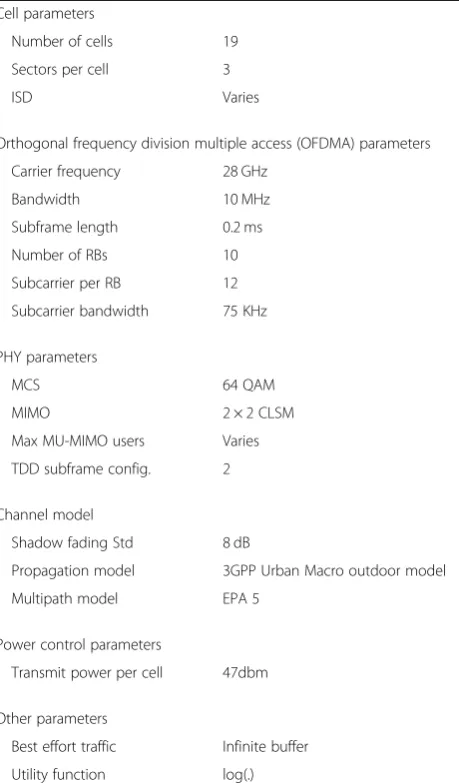
Table 3Simulation set-up
Cell parameters
Number of cells 19
Sectors per cell 3
ISD Varies
Orthogonal frequency division multiple access (OFDMA) parameters
Carrier frequency 28 GHz
Bandwidth 10 MHz
Subframe length 0.2 ms
Number of RBs 10
Subcarrier per RB 12
Subcarrier bandwidth 75 KHz
PHY parameters
MCS 64 QAM
MIMO 2 × 2 CLSM
Max MU-MIMO users Varies
TDD subframe config. 2
Channel model
Shadow fading Std 8 dB
Propagation model 3GPP Urban Macro outdoor model
Multipath model EPA 5
Power control parameters
Transmit power per cell 47dbm
Other parameters
Best effort traffic Infinite buffer
Utility function log(.)
Our proposed two-level IC approach employs a dynamic time domain IC approach at the intercluster level to col-lect interference information for the cluster-edge UE and allocate the UE dynamically among the clusters. To evalu-ate the dynamic characteristic of our proposed approach, we implement a two-level IC approach that uses the static fractional frequency reuse (ReUse3) approach to mitigate intercluster interference, which is referred to as a two-level static intercluster IC approach. The ReUse3 ap-proach splits the spectrum into three bands among neigh-boring clusters. The bands are assigned in a way that the clusters using the same band are separated as far as pos-sible to reduce intercluster interference.
Figure11compares the average sector throughput and the SINR at a 5% tail for our proposed two-level IC ap-proach and the two-level static intercluster IC apap-proach by using the same set-up as described in Fig.8 (DIC P2). Although the edge performance of the two-level static in-tercluster IC approach is better than that of our proposed two-level IC approach, this improvement is achieved by significantly sacrificing cell capacity.
6 Complexity analysis
This section analyzes the communication and computa-tional complexity of the proposed approach. For the
communication complexity, additional CQI feedback is required during the interferer information collec-tion phase for only a fraccollec-tion of the time for the UEs at the cluster’s edge or the UEs with bad RF. Assum-ing an FWA application with a slow varyAssum-ing channel and no significant traffic change during a period of transmission, the air-link overhead is small. Intraclus-ter scheduling outputs are exchanged between the RRH and BBU. With CRAN architecture, the RRH and BBU are connected using a dedicated network, such as fiber links. For small cluster sizes, both delays [38] and data volume are less of an issue. The forbid-den relationship tables on each BBU are built, ex-changed, and updated between the BBUs or with a center unit at the beginning of the intercluster sched-uling period and are used during the period; here, as-suming there is a slow varying channel, latency is not a concern.
Regarding the computational complexity on the UE side, during the data collection phase, multiple versions of SINRs corresponding to different interference scenarios must be calculated; on the BBU side, the intracluster scheduling used a greedy algorithm with a complexity ofOðjCj U2cÞ, where |C| is the number of clusters within the network;Uc is the total number of UEs within a cluster, which is equal Fig. 9ISD 200, 20 UE scenario with P1 optimization
to Cmax×Us; Cmax is the max cluster size; and Us is the number of UEs per sector. For intercluster scheduling, only the assigned cluster-edge UEs trigger intercluster schedul-ing. For a distributed approach, the complexity is O(N× log(N) ×Ue), where Ue is the number of assigned cluster-edge UEs, N is the number of cells in the net-work, and O(N× log(N)) is the complexity of the sorting. For the centralized approach, the complexity of the algo-rithm is dominated by the graph built with a complexity of O(Ue×N) and breadth-first cluster partitioning with a com-plexity ofO(Ue2) and with an exhaustive search within each
cluster that has a complexity of O(Ue× 2l), wherel repre-sents the maximum interference group size. By setting the maximum group size to a low value, we can reduce the computational complexity.
7 Conclusion
We introduced novel two-level IC approaches to address the problem of coordinating users and beams within a large network for a SBS. The general problem was for-mulated, and the performance was investigated using simulations on a hexagonal model cellular network. The Fig. 11Dynamic vs. static: ISD 200, 20 UE scenario with P2 optimization
Table 4Compared algorithms
Compared algorithms
Beamforming Network clustering Intra-cluster target Inter-cluster target Inter-cluster interference group partitioning
BaseLine BF P2 Yes No No No No
Coordinated BF IC P2 Yes Yes P2 No No
TwoLevel DIC P2 Yes Yes P2 P2 No
BaseLine BF P1 Yes No No No No
Coordinated BF IC P1 Yes Yes P1 No No
TwoLevel DIC P1 Yes Yes P1 P1 No
TwoLevel CIC P1 Yes Yes P1 P1 Yes
coverage and capacity trade-off was studied for different IC approaches, and the performance of the coordinated two-level IC approaches was compared with uncoordinated and coordinated MU-MIMO systems. It was shown that the coordinated two-level IC approach’s edge performance is higher than that of both the uncoordinated and coordi-nated MU-MIMO systems but at different levels of sacri-ficing cell capacity.
Abbreviations
3GPP:3rd Generation Partnership Project; AAS: Adaptive array systems; ABS: Almost blank subframe; BBU: Baseband unit; BTS: Base station; CBF: Coordinated beamforming; CBIC: Carrier aggregation-based IC; CLSM: Closed loop spatial multiplexing; CPRI: Common public radio interface; CQI: Channel quality indicator; CRAN: Cloud-RAN; CSI: Channel-state information; eIC: Enhanced IC; EPA: Extended pedestrian A; FFR: Fractional frequency reuse; FIC: Frequency domain IC; GIC: Graph-based IC; HPBW: Half power beam width; IC: Interference coordination; ICI: Intercell interference; MAC: Media access control; mmWave: Millimeter wave; MU-MIMO: Multiuser multiple input and multiple output; PCC: Primary component carrier; PFR: Partial frequency reuse; PMI: Precoding matrix indicator;
QAM: Quadrature amplitude modulation; RB : Resource block; RRH: Remote radio headers; SBS: Switched-beam system; SCC: Secondary component carrier; SFR: Soft frequency reuse; SINR: Signal-to-interference-plus-noise ratio; SLNR: Signal-leakage-plus-noise ratio; TDD: Time division duplex; TIC: Time domain IC; TTI: Transmission time interval; UE: User equipment; UFR: Universal frequency reuse; UIC: Utility-based IC
Acknowledgements Not applicable.
Funding Not applicable.
Availability of data and materials
The dataset supporting the conclusions of this article is available in the figshare repository, with the unique persistent identifier and hyperlink to the dataset inhttps://figshare.com/articles/5GICIC-data/7730609.
Authors’contributions
JW, OB, and JW conceived and designed the study. JW performed the simulations. JW wrote the paper. All authors reviewed and edited the manuscript. All authors read and approved the final manuscript.
Competing interests
The authors declare that they have no competing interests.
Publisher’s Note
Springer Nature remains neutral with regard to jurisdictional claims in published maps and institutional affiliations.
Author details
1Department of Electrical and Computer Engineering, University of
Massachusetts, Lowell, MA 01854, USA.2Graduate School of Science and Engineering, Istanbul Kemerburgaz University, Istanbul, Turkey.3Instart Logic
450 Lambert Avenue, Palo Alto, CA 94306, USA.
Received: 30 November 2017 Accepted: 6 February 2019
References
1. K.T. Kim, S.K. Oh, inProc. 65th IEEE Vehicular Technology Conference 2007, Dublin, Ireland. A universal frequency reuse system in a mobile cellular environment (2007), pp. 2855–2859
2. A. Eisenblatter, M. Gretschel, and A. M. Koster,“Frequency planning and ramifications of coloring,”ZIB-Report 00–47, 2000
3. R. Kwan, C. Leung, (2010) A survey of scheduling and interference mitigation in LTE. J. Elect. Comput. Eng.2010, Article ID 273486.https://doi. org/10.1155/2010/273486
4. S.E. Elayoubi, O. Ben Haddada, B. Fourestie, Performance evaluation of frequency planning schemes in OFDMA-based networks. IEEE Trans. Wireless Commun.7, 1623–1633 (2008)
5. Ericsson A,“Inter-cell interference handling for E-UTRA,”Tech. Rep. TSG-RAN WG1 R1–050764, 3rd Generation Partnership Project (3GPP), Aug.–Sep. 2005
6. X. Fan, S. Chen, X. Zhang, inProc. of the International Conference on Wireless Communications, Networking and Mobile Computing (WiCOM‘07), Shanghai, China. An inter-cell interference coordination technique based on users’ ratio and multi-level frequency allocations (2007), pp. 799–802 7. Nokia, in3GPP Project Document R1–060291. OFDMA downlink inter-cell
interference mitigation (Feb. 2006)
8. Huawei,“Soft frequency reuse scheme for UTRAN LTE.”3GPP Project Document R1–050507, May 2005
9. A. Simonsson, inProc. 65th IEEE Vehicular Technology Conference 2007, Dublin, Ireland. Frequency reuse and intercell interference co-ordination in E-UTRA (2007), pp. 3091–3095
10. T. Novlan, J. Andrews, I. Sohn, R. Ganti, A. Ghosh, inProc. IEEE Globecom, Miami, Florida. Comparison of fractional frequency reuse approaches in the OFDMA cellular downlink (2010), pp. 1–5
11. T. D. Novlan, R. K. Ganti, A. Ghosh, and J. G. Andrews (2011, Jan.), Analytical evaluation of fractional frequency reuse for OFDMA cellular networks ArXiv [Online]. Available:http://arxiv.org/abs/1101.5130
12. L. Lindbom, R. Love, S. Krishnamurthy, C. Yao, N. Miki, V. Chandrasekhar, Enhanced inter-cell interference coordination for heterogeneous networks in LTE-advanced: a survey(CoRR, 2011)
13. L. Garcia, K. Pedersen, P. Mogensen, Autonomous component carrier selection: Interference management in local area environments for LTE-advanced. IEEE Commun. Mag.47(9), 110–116 (2009)
14. S. Deb, P. Monogioudis, J. Miernik, J.P. Seymour, Algorithms for enhanced inter-cell interference coordination (eICIC) in LTE HetNets. IEEE/ACM Trans. Netw.22(1), 137–150 (2014)
15. M.S. Ali, An overview on interference management in 3GPP LTE-advanced heterogeneous networks. Int. J. Future Commun. Networking8(1), 55–68 (2015) 16. M.C. Necker, inProc. of the 10th ACM Symposium on Modeling. Coordinated fractional frequency reuse (Analysis and Simulation of Wireless and Mobile Systems, New York, NY), p. 2007
17. Y.J. Chiang, Z. Tao, J. Zhang, C.C.J. Kuo, inProc. of the IEEE Global Telecommunications Conference, New Orleans, LA. A graph-based approach to multi-cell OFDMA downlink resource allocation (2008)
18. R.Y. Chang, Z. Tao, J. Zhang, C.-C.J. Kuo, inProc. of the IEEE International Conference on Communications, Dresden, Germany. A graph approach to dynamic fractional frequency reuse (FFR) in multi-cell OFDMA networks (2009) 19. M. Rahman, H. Yanikomeroglu,Enhancing cell-edge performance: a downlink dynamic interference avoidance scheme with inter-cell coordinationIEEE Trans. Wireless Communication.9(4), 1414–1425 (2010)
20. M. M. Rahman,“Dynamic inter-cell interference coordination in cellular OFDMA networks”, Department of system and computer engineering, Queens University, pp. 1–117 (2011)
21. M. Rahman, H. Yanikomeroglu, W. Wong,Interference avoidance with dynamic inter-cell coordination for downlink LTE systemProc. IEEE Wireless Commun. Netw. Conf. (WCNC) (2009)
22. Y. Niu, Y. Li, D. Jin, L. Su, A.V. Vasilakos, A survey of millimeter wave communications (mmWave) for 5G: opportunities and challenges. Wirel. Netw21(8), 2657–2676 (2015)
23. U. Jang, H. Son, J. Park, S. Lee, CoMP-CSB for ICI nulling with user selection. IEEE Trans. Wirel. Commun.10(9), 2982–2993 (2011)
24. H. Dahrouj, W. Yu, Coordinated beamforming for the multicell multiantenna wireless system. IEEE Trans. Wirel. Commun.9(5), 1748–1759 (2010) 25. E. Bjornson, N. Jalden, B. Ottersten, Optimality properties, distributed
strategies, and measurement-based evaluation of coordinated multicell OFDMA transmission. IEEE Trans. Signal Process.59(12), 6086–6101 (2011) 26. D.H.N. Nguyen, T. Le-Ngoc, Multiuser downlink beamforming in multicell
wireless systems: a game-theoretical approach. IEEE Trans. Signal Process. 59(7), 3326–3338 (2011)
28. Motorola,“SCF-based COMP: Iterative scheduler algorithm and performance gain over single-point SU/MU beamforming,”Motorola, Tokyo, Japan, Tech. Rep. 3GPP TSG RAN WG1 #58bis R1–093963, 2009
29. Mitsubishi,“Low-complexity precoding for LTE—A collaborative MIMO: a signal leakage approach, Mitsubishi Elect.,”Slany, Czech Republic, Tech. Rep. 3GPP TSG RAN WG1 #55 R1–084482, 2008
30. K. Kwak, H. Lee, H. W. Je, J. Hong, S. Choi, Adaptive and distributed CoMP scheduling in LTE-advanced systems. (VTC Fall) IEEE 78th, pp. 1–5 (2013) 31. A. Michaloliakos, W.C. Ao, K. Psounis, Joint user-beam selection for hybrid
beamforming in asynchronously coordinated multi-cell networks. Proc. ITA, pp. 1–10 (2016)
32. A. Adhikary, G. Caire,JSDM and multi-cell networks: handling inter-cell interference through long-term antenna statisticsIEEE Asilomar, pp. 649–655 (2014)
33. J. Wang, H. Zhu, in2015 IEEE Int. Conf. Commun. (ICC), London. Beam allocation and performance evaluation in switched-beam based massive MIMO systems (2015), pp. 2387–2392
34. K. A. Gotsis et al.,“Beamforming in 3G and 4G mobile communications: the switched-beam approach,”in Recent developments in mobile
communications–a multidisciplinary approach, J. P. Maicas, Ed. Rijeka, Croatia: In Tech, 2011, pp. 201–216
35. C.Y. Tung, C.Y. Chen, H.Y. Wei, in11th Int’l Conf. on Heterogeneous Networking for Quality, Reliability, Security and Robustness (Qshine 2015), Taipei, Taiwan. Next-generation directional mmWave MAC time-spatial resource allocation (2015)
36. Cisco, Ericsson, Intel Corp., LG Electronics, Nokia, Qualcomm Technologies Inc., Samsung Electronics, and Verizon,“Verizon 5th Generation Radio Access; Physical channels and modulation (Release 1)”.http://www.5gtf.net/ V5G_211_v1p7.pdf
37. 3GPP TR 38.900 v14.2.0,“Study on channel model for frequency spectrum above 6 GHz,”(2016).https://www.etsi.org/deliver/etsi_tr/138900_138999/ 138900/14.02.00_60/tr_138900v140200p.pdf
38. inUnderstanding switch latency”[White paper]. Cisco (2012)
39. 3GPP TR 25.996,“Spatial channel model for Multiple Input Multiple Output (MIMO) simulations”(2012).https://www.etsi.org/deliver/etsi_tr/125900_ 125999/125996/11.00.00_60/tr_125996v110000p.pdf
40. Cisco, Ericsson, Intel Corp., LG Electronics, Nokia, Qualcomm Technologies Inc., Samsung & Verizon,“Verizon 5th Generation Radio Access; Physical layer procedures”.http://5gtf.net/V5G_213_v1p4.pdf.