resolution of passive radar target recognition
based on WiFi signals
Xiaokun Zheng
1,2*†, Ting Jiang
1†and Wenling Xue
1,2Abstract
To improve the resolution of passive radar target recognition based on WiFi signals, a composite preamble scheme is proposed. In addition, a composite approach combined with cancelation and decomposition in an interior scenario is studied. With this method, short sensing signals, such as chirps with no extra bandwidth, are overlayed onto a long WiFi preamble (802.11a) in the time domain. After detection and coarse sync using the short preamble at the Rx side, most of the chirp signal is removed prior to fine channel estimation (CE). Although the slight influence on CE may cause a fractional increase in the relative constellation error, the method can obtain a higher communication performance than normal multiplex integration. Finite-difference time-domain (FDTD) simulations show that when the same time-domain features are extracted, the composite signal provides a better recognition effect than when only using the WiFi preamble. The method is useful for health care such as elderly toilet/bathroom standing/lying detection, or device-free people counting.
Keywords: Recognition method, Improve correctness, WiFi, Composite signal
1 Introduction
The Internet of Things (IOT) is being propelled by the convergence of sensing, communication, computing, and control. Integrated smart sensing and communication is a hot issue for communication terminals. It is impor-tant in the fields of health care, military, transportation [1], industrial monitoring, border patrol, etc. The key to signal integration is to design a waveform that simultane-ously provides the functionalities of communication and sensing.
Traditional radar technology, such as bistatic radar [2], was initially used for smart sensing. Then, in [3,4], WiFi signals were used for human fall detection and gesture recognition, [3] reported 87% or 90% fall detection accu-racy when magnitude of CSI or the phase difference across multiple antennas was used, and [5, 6] discussed multi-static passive radar using WiMAX and RFID; however,
*Correspondence:[email protected]
†Xiaokun Zheng and Ting Jiang contributed equally to this work. 1Key Labs of Universal Wireless Communications, Beijing University of Posts and Telecommunications, 100876 Beijing, China
2College of Electronics Information and Engineering, Hebei University, Wusi East Road, 071002 Baoding, China
their sensing resolutions were generally relatively limited. Yu Guo, Usman Mahmood, Zhong et al. [7–9] used deep learning/SVM classification based on privileged informa-tion or fourth-order cumulant to improve recogniinforma-tion correctness. On the other hand, to achieve higher resolu-tion, certain signals suitable for sensing have been used to recognize and transmit data simultaneously. For example, LFM-MSK or FMCW [10] based on chirp signals, are used for integrated systems with relatively low data rates; in [11], pulse waveform OFDM was used for high-resolution detection, although its synchronization is costly.
Various multiplexing-based methods, such as time [1], frequency [12], code [13], and spatial-division multiplex integration [14], have also been proposed, whereby both data rate and sensing resolution can achieve a relatively high performance. Moreover, cancelation technology is used to reduce interference between the sensing carrier and the transfer sub-carrier in MIMO-OFDM integrated systems [15]. Mark Roberton proposed a chirp spread-spectrum signal [16], with the help of de-spreading to reduce mutual interference.Then long pseudo random code is generally needed and data rate is affected. In [17], CP-based OFDM high-resolution imaging, which requires
a sufficient cyclic prefix, was proposed. Multiplex mode generally requires more resources.
A composite integration is proposed in this paper. Our main contributions are as follows. (1) A composite pream-ble scheme is proposed to improve the target recognition resolution of passive radar using WiFi. Thereby, a higher communication performance than normal multiplex inte-gration can be obtained. The composition can only be applied at the Tx side. It can also be applied at both the Tx and Rx sides, which means that the preamble at the Tx and Rx sides can be replaced by the same compos-ite preamble simultaneously. (2) The synthesis can be in the time domain, or in the frequency domain which pos-sesses good autocorrelation, anti-fading performance and sharper ambiguity function. Thus, the channel estima-tion of the long preamble is retained, and its recogniestima-tion resolution is improved. (3) In this paper, a time-domain composite at the Tx side combined with cancelation and decomposition is studied. We verified that the method can improve the resolution of object recognition for inte-rior scenes. The scene can be empty; it can also include some fixed arrangement. And we are adding more perti-nent recognition test for application-specific scenario; we will also focus on applying suitable composite(such as f-domain composite) preamble at both the Tx and Rx sides next; there would then be no need to consider the effects of deletion and residues.
In this paper, we emphasize the time domain. The wave-form of the data section varies with the transmitted data, and it is rather complex for use in recognition tasks [4]. Thus, we use the preamble, and a short sensing signal, such as a chirp with no extra bandwidth, is overlaid onto the long preamble of 802.11a WiFi [18]. After detection and coarse sync at the Rx side, the pre-process or pre-fade chirp signal is removed according tok·Tstepbased on the
coarse sync and using a parallel correlator [19,20]. Here, Tstep is the delay increment step,k = 0, 1, 2. . . . Then,
the residual jamming signal is decomposed when the long preamble makes correlation with many correspond-ing delays local sequences (Fig. 2b). OFDM can be used to transfer data at high speed in the data section, and the sensing part is easy to extract. A small constant-amplitude overlapping chirp at the transmitter has a minimal effect on the peak-to-average-power ratio (PAPR). The power of the overlapping signal can be easily adjusted according to the sensing precision and CE precision, and the system change is smaller than time multiplex integration [1]. The FDTD simulation shows that the composite signal pro-vides better recognition performance than simply using the WiFi preamble. Although there is a slight influence on frequency offset (FO) estimation and frequency-domain equalization (FDE) [21], which may cause a fractional increase in the relative constellation error (RCE) [18], the method still has a relatively high data transmission
capacity. The method is useful for device-free people counting [22] at the entrance, such as making a distinction between adults and children. And it is useful for fall detec-tion in toilet/bathroom, etc, such as there was a nearly 100% human standing/lying recognition accuracy in the simulation in this paper when preamble signal was used.
The remainder of this paper is organized as follows. The scheme of the signal composite integration is introduced in Section2. The principle and scheme of the separation method are introduced in Section3. Section4 presents the FDTD-based simulation results and discussion. The conclusion is provided in Section5.
2 Methods of the composition
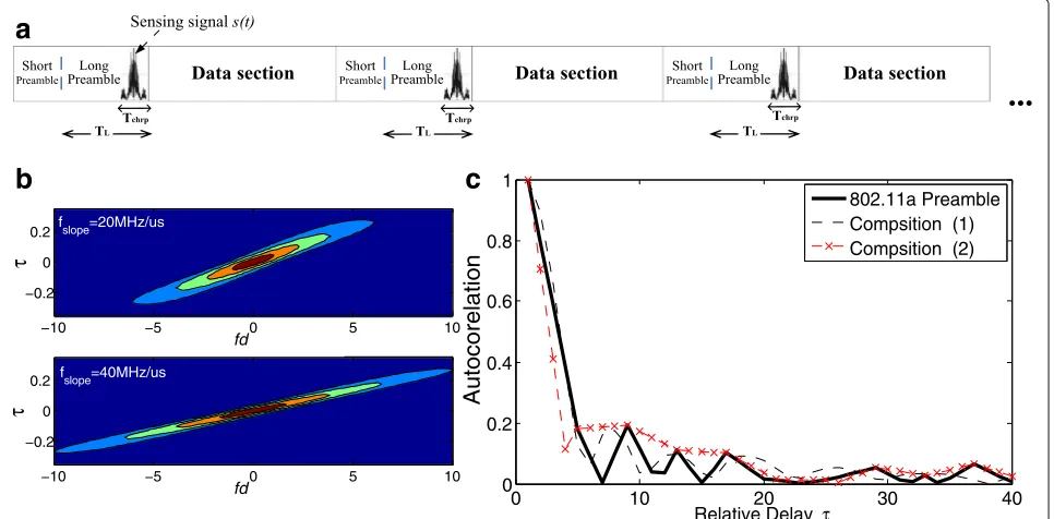
To improve the recognition resolution of WiFi signals and reduce the impact on communication, a short sensing sig-nal is overlaid onto its long preamble, with neither extra bandwidth nor time slots required, as shown in Fig.1. The data section varies with the transmitted data; it is too com-plex to be used for recognition [5]. Therefore, we use the preamble. The duration or power of the overlapping can be adjusted.
The composite preamble signal is expressed as (1, 2), whereLa(t)is time domain of the 802.11a long preamble, Lis frequency-domain,L={00000, 1, 1,−1. . .1, 1, 000000} and La(t)=
k
Lk·exp(j2πkFt)=IFFT(L) [18]. s(t) is the
short sensing signal, TL andTchrpare the duration times
of La(t) and s(t), respectively.
Pr(t)=
Figure1cshows that both of the compositions have good autocorrelation. However, for the reason that the overlaid signal is an envelope signal, anti-fading performance of composition (1) is slightly worse when CE is performed, (1) is not quite suitable for replacing original preamble at both Tx and Rx sides directly. So in this paper, we emphasize the time-domain composition at Tx side; and the sensing signals(t)is removed and decomposed at Rx side. Composition in f-domain (2) will be researched next. Here, we select a chirp as the sensing signal, and we use the composite fragmentLa(t)+s(t)for recognition.s(t) fslope is the slope and U(t) is the roughly constant
enve-lope pulse in this paper. If the power of the chirpPchrpis less than 1.2 times the long preamblePL, recognition cor-rectness will not increase noticeably (Fig. 4a); therefore, Pchrpshould be > 1.2PL. On the other hand, ifPchrp is
b
c
Fig. 1Signal composition integration.aOverlaying the sensing signal onto WiFi.bAmbiguity function with differentfslope.cAutocorrelation of composition
correctness will greatly decrease, and FDE cannot be com-pleted (see Figs.4band7a). Moreover, whenPchrp=2PL, a satisfactory increase in the recognition correctness can be obtained (Fig. 9). Thus, 1.2PL < Pchrp ≤ 2PL is recommended.
With the same powerPchrp, a longerTchrp results in a
more serious influence on FO estimation and FDE. In the case ofPchrp = 1.2PL, when Ts= 1 us, the correctness will greatly decrease as well (Fig.4b). Thus,Pchrpcannot
be smaller, and therefore, Ts1 us is required. On the other hand, ifTchrpis too short, an insufficient number of sam-ple points will be obtained, and the recognition task will not be performed accurately. As described by the USRP (Universal Software Radio peripheral) data sheet [23], if we set the front-end sample rate asfs=200 MHz andTchrp
<0.25 us, <50 sample points can be used for recogni-tion, which cannot achieve complete complex recognition. In addition, considering that general radar signal process-ing boards support higherfs, we emphasizefs =200 and 400 MHz and Ts=0.5 us in the FDTD simulation in this paper.
With the same duration and bandwidth, fslope of the
chirp signal modulated with single-side band (SSB) tech-nology could have a greater value than DSB. 802.11a uses a bandwidth of 20 MHz [18]; when the chirp signal is mod-ulated with DSB, itsfslope can be less than approximately
20 MHz/us (here, Ts= 0.5 us). Then, it would occupy a bandwidth of less than 20 MHz. On the other hand, when modulated with SSB, its frequency change ratefslopecan
be less than approximately 40 MHz/us. Equation (3) is the ambiguity function of the chirp signal [24]. We can see that a largerfsloperesults in a more pronounced spike and
higher resolution. Figure1bshows the ambiguity function with differentfslopewithout extra bandwidth.
x(τ,fd)2=
(Tchrp− |τ|)·sinc((fd−fslopeτ)(Tchrp− |τ|))2|τ|<Tchrp
0 else
(3)
3 Methods of cancelation and decomposition
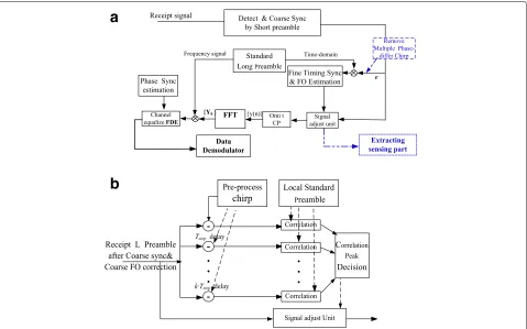
The composite signal can be used for recognition. In addition, when channel estimation (CE) is performed, the chirp signal should be removed. Figure 2shows the scheme for extracting the sensing part and the scheme for removing when CE. After detection and coarse sync by the short preamble at the Rx side, the pre-process chirp is removed according tok·Tstepbased on both the coarse
sync (k = 0, 1, 2,. . .) and the sliding parallel correlator [20, 21,25]. Then, the residual jamming is decomposed when the long preamble makes a correlation with local sequence and makes FFT for FDE.
3.1 Removing overlapped signal
To guarantee the channel estimation performance of the synthesis preamble, before being correlated with multiple delay-differentk·Tsteplocal sequences, the corresponding
phase chirp is removed according tok·Tstepbased on the
a
b
Fig. 2Separate sensing and CE based on 802.11a.aSeparate FO estimate, FDE and sensing.bRemoval based on sliding parallel correlator
correlator to fine tune the sync. Based on the coarse sync, parallel correlators do not require too many resources. In addition to the chirp signal on the Tx side, it can be con-sidered for removing pre-fade or pre-processing the chirp signal. Here, the pre-processed signal is defined as
Spre(f)=H(f)·S(f)+Ni(f) (4)
where S(f) is the chirp signal on the Tx side, andH(f) is the transfer function of the interior scene without the sensing object and no people (It can be empty or include some fixed arrangement).Spre(f)can be recorded in advance for a given scenario, where the locations of the transmitter and receiver are fixed and there are neither sensing objects nor people. The interior scene could be viewed as a waveguide; we use the FDTD method [26,27] to achieve accurate computation.
The insertion of the sensing object will cause a distur-bance in the electric field distribution. Let H(f)denote the new transfer function, and the received signal isSr(f). Then,
Sr(f)=H(f)·S(f)+Ni(f) (5)
After removing the sendingS(f)or pre-processedSpre(f),
the remainder areSrest(f)orSprest(f), respectively:
Srest(f)=[H(f)−1]·S(f)+Ni(f), and (6) Sp_rest(f) =[H(f)−H(f)]·S(f)+[Ni(f)−N(f)] In real applications,Srest(f),Sp_rest(f)or their mean value
can be measured; they can then be compared to decide which should be removed. In this paper, the sensing objects are mainly hollow balls with diameters of 21 cm and 22 cm, the disturbance is small, and we select pre-processed signals for removal in our simulation test.
Figure 3 shows theSpre(f) andSr(f) signals recorded by the recorder of the FDTD simulation; here, after the FDTD calculation, we introduce noise with an SNR of 6.5 dB. In addition, when we perform FO estimation, FDE and recognition tests, [−4∼16 dB] SNRs are considered in Figs.4, 9, and 10. The dotted line representsSpre(f),
and the solid line representsSr(f)with the object. We can see the difference caused by the insertion of the sensing object. Table1 shows the removal of the residue in our study.
Fig. 3Difference in received signal caused by sensed object
a
b
Table 1Residue vs. sync precision
Chirpfslope Sync precisionTstep Residue ratiow
≤20 MHz/us 5 ns 50%
≤40 MHz/us 2.5 ns 43%
3.2 Residual decomposition and marginal impact on CE There is a residual after removal due to the sync precision and nonlinear variations. The residual will be decomposed when the long preamble makes a correlation for the time sync and fine FO estimation; it will also be decomposed when the FFT is performed for frequency-domain equal-ization. Here, we focus on fine FO estimation for illus-tration. We use a step-search method, where fstep is the
step size in the search.Pr(t)is the composite preamble at the transmitter, as shown in Eq. (1).Pr(t)is the received composite preamble at the receiver after coarse offset cor-rection, and its discrete form isPr(n) =Pr(nTs)ej2πfnTs. Here, f denotes the residual fractional offset and f∈[fmin,fmax] . Equation (7) shows that the received composite pream-ble correlates with the different local FO sequences.lis the sample point number of the entire received long pream-ble (Pr(t)), andiis the sample number of the composite
Table 2Integrated signal parameters
Duration Period Average
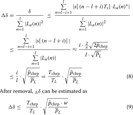
δin Eq. (7) determines the influence of the overlap:
δ= relative errorδcan be estimated as
δ= l δ
After removal,δcan be estimated as
δ≤ Tchrp
wherep¯Landp¯chrpare the average powers of the preamble
and chirp, π22p¯chrp in Eq. (8) is the mean value of the
constant envelope|Chirp|, andwis the residue rate. In this paper, we focus on the influence of the removal and residual on fine FO estimation and equalization. The influence on time sync is relatively small. We also rec-ommend using the composite signal as the long preamble directly for the fine time sync, FDE, etc., therein replac-ing the original preamble at the Tx side (transmitter) and Rx side (receiver). This is one of the next steps in our research.
3.3 Extracting sensing part for recognition
The composite sensing signal is extracted after the time sync, and the composite signal fragment is used directly for recognition:
La(t)+s(t) TL−Tchrp<t≤TL (10) Combined with a current recognition algorithm based on UWB or WiFi [9,28], it can be used to sense the shape and size of an object.
4 Experimental
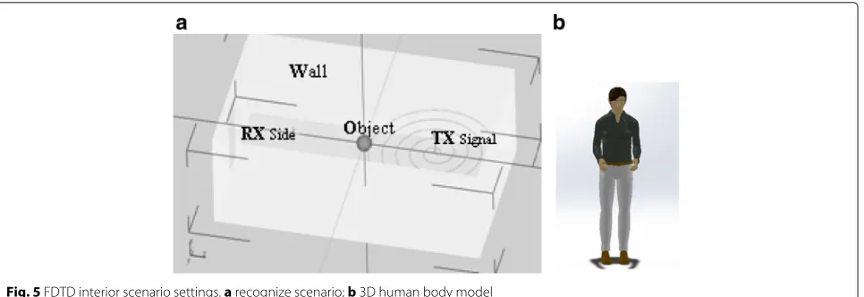
Fig. 5FDTD interior scenario settings.arecognize scenario;b3D human body model
versus data rate” in 802.11a, we obtain the allowed rate under different RCE and make an evaluation of the trans-mission. Finally, we test out the target recognition by using the preamble signal.
4.1 Frequency offset estimate
Fine FO estimation and FDE are the main functions of the long preamble. Impacting on FO estimation due to the composition will increase rotation error of the con-stellation. So in this section, we simulate FO estimation by using composite preamble, and Fig.4is drawn. Then, according to the result, we calculate the effect on RCE. To consider the influence on fine FO estimation, we use MATLAB 2014a; And in the next two sections, we use the eastwave FDTD electromagnetic platform.
802.11a [18] is the reference for the simulation parameters. The long preamble La is the IFFT of L = {000000 ,L−26,26, 00000}, where L−26,26 =
{1, 1,−1,. . .,−1, 1, 1, 1, 1} , and long preamble includes two L periods 2TFFT. On the Rx side, it correlates with the
local sequences for fine FO estimation based on a step-search method, and the coarse offset has been corrected based on the short preamble. And we set front-end sam-ple ratefs = 400 MHz, Tstep = 2Ts = 5 ns, the power of the overlapped chirp Pchrp is 1.2 to 2 times the long
preamblePL.
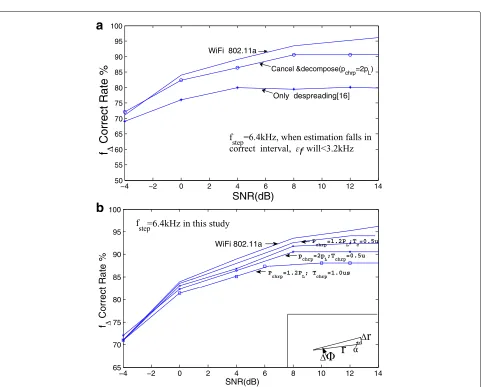
For the reason that the increase in the error rate is not noticeable when the FO errorf < 10 kHz [29], we set fstep = 6.4 kHz. In this way if the FO estimation falls in the correct interval,f will be 3.2 kHz, which meets the requirement off <10 kHz. Even if the estimated results fall in the adjacent area,f < 6.4 kHz only slightly increase the rotation error of constellation,will not affect the follow-up equalization estimation (see Fig.7and rel-evant explanation in 1st paragraph of Section4.2.3). See Table2for the other parameters.
Figure 4 is the result of FO estimation using com-posite preamble vs.original preamble. Figure 4a shows
that the FO estimation accuracy is decreased by approxi-mately 3–4% under high-signal-to-noise-ratio (SNR) con-ditions after overlap and removal, and the accuracy is greater than only de-spreading is performed [16]. And as a result of f · t=φ, FO estimation error f will increase the rotation error of the constellation(φ).When φ is very small, r/r≈ sinφ ≈ φ (see the small graph inserted in Fig.4, α ≈ 90◦ there), herer is mag-nitude of the point in constellation, r is magnitude of the constellation error.Hence,it can be considered that the 3-4-%f error leads to the corresponding increase in RCE. And since the small increase of f does not affect the completion of the following FDE, we can add together the RCE increase derived in this section and the increase derived in next section, then we get the total RCE increase, no more consideration of mutual influence.
Figure4b shows thef accuracy curve with chirps at varying powers, where the power is easy to adjust accord-ing to the estimation and recognition precision. The curves are flatted at high SNR, with a flooring effect being exhibited [30]. This shows that to further improve estima-tion and recogniestima-tion concurrently, we must improve the removal effect.
4.2 Frequency-domain equalization 4.2.1 FDTD scenario and calculation settings
The FDTD simulation provides greater accuracy than the general multi-path model [31]. We use the eastwave
Table 3FDTD calculation settings
Fig. 6FDTD excitation source settings
FDTD simulation platform, which is China’s first paral-lel all-vector electromagnetic simulation platform. The platform is based on a strict FDTD and physical optics model; its calculation speed is 10 to 100 times higher than similar algorithms found worldwide. The parameters
of the FDTD simulation were set as 2.9×1.5×2 m based on our lab, where the distance between the RX and TX antennas is 1.6 m and the length of an antenna is 12 cm. The sensed object is placed in the middle. Figure5shows the FDTD scenario.
a
b
Referring to 802.11a and the overlapping scheme in Fig.1, we set our FDTD excitation source as shown in Fig.6. The data of the FDTD recorder is output to Matlab2014 for
data processing. Under 802.11a,La(t) = wTlong(t)
window andTG12is the guard interval. The discrete form
of the long preamble isLa(k)=wTlong(k)·IDFT64(L), and Re[ifft(L)], and the Q channel is endowed with Im[ifft(L)]. Then, we obtain the integrated signal as shown in Fig.6.
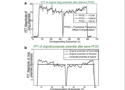
4.2.3 Equalization results
Figure7ais the FFT of the received preamble under vary-ing fractional frequency offset compensations (FFOC). The figure shows that the preamble can achieve FDE even when fractional FO estimated valuef has a slight error (Whenfhas a slight error such asf=6.4kHz here, the FFOC will change as well, and then the curve is slightly different.However,the FDE can still be achieved). [29] also indicates that f is allowed a certain error. In addition, from the perspective of the sum of squared deviations (SSD), the line is flattest when FFOC = -120 kHz, and thus, -120 kHz may provide the best performance. SSD is
defined as
Figure7bshows the FFT of the WiFi preamble (solid line sn) and the FFT of the composite preamble after removal on the Rx side (dotted line dn) after compensation at -120 kHz.mn(marked line) is WiFi at the transmitter. Thus, sn − mn is the equalization coefficient, and dn − sn is the equalization error due to the residual. We defined the relative equalization error:
[dn−sn]2/ [sn−mn]2= J n=1, 2, 3. . ., 64 (11)
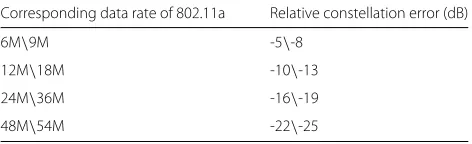
By computation,J = 9.5% slightly increases RCE, and taking into account the 3% increase in phase rotation RCE caused by the fre-offset error mentioned in Section4.1, it will lead to an increase in the RCE from -25 dB to -16 dB or -19 dB to -13 dB. Accordingly, the data rate decreases from 54 Mbps to 24 Mbps or 36 Mbps to 18 Mbps (Table4).
48M\54M -22\-25
(if the sync precision improves toTstep=2.5 ns, the data rate decreases from 54 Mbps to approximately 48 Mbps)
4.2.4 Assessment of the communication
According to the test results,analytical,calculation in 4.1 and 4.2.3: FO estimation error increases the rotation error of constellation, equalizing compensation error causes the diffusion of constellations. Combining the results of the two, the total RCE increase due to the composition is got. And then according to Table90 in 802.11a (Table4in this paper), we obtain the allowed rate under different RCE, Table5is got and Fig.8is drawn.
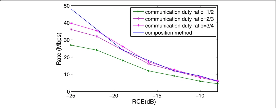
Table 5 shows the Rbmax comparison of some super-resolution design methods occupying the same 20 MHz of bandwidth, except the time-division integration [1] is 100 MHz of bandwidth.
Figure8 shows the assessment of the communication capability compared to time-division (TD) multiplex inte-gration when they are applied to the same OFDM modu-lation based on 802.11a. Here, communication duty ratio (C duty ratio) is the communication proportion under TD multiplex integration. For TD integration mode, with the increase of the C duty ratio, its transmission capac-ity increases;and when C duty ratio is from 2/3 to 3/4, or from 3/4 to 4/5..., the increase is getting slower. The data rate of composition mode is not very different from the TD mode when C duty ratio of the TD mode is more than 3/4. In addition, composition mode has certain advantage when RCE is less than−22 db, and then we say that it has a high transmission capacity.
4.3 High-resolution recognition
We use the output of the FDTD simulation in Section4.2 to compare the recognition effect of only using WiFi and when using the composite signal. Two groups of experi-ments were performed. One group attempts to distinguish
Table 5RbmaxPerformance comparison
Integration method Rbmax
Composition in this study 24 M/48 Mbps
20M pulse OFDM [11] 5.4 Mbps
Fig. 8Assessment of the composite method vs. time multiplex integration
between a basketball (25 cm) and a volleyball (21 cm); the other group attempts to distinguish between a football (22 cm) and a volleyball. Besides identifying balls with different diameters,we also added a human standing/lying recognition simulation. The height of the 3D human body model is set to 1.55 m(see Fig. 5b), and the simulation result is drawn in Fig.5b.
Based on the normalization of the long preamble, time-domain features of the composite signal fragment were extracted, including the energy, excess delay, rms delay, maximum value, standard deviation, and peak value. The SVM classifier svmtrain and thesvmpredict function in MATLAB2014 were used in both experiments. A radial basis kernel was used, and the parameterscandgwere set to 1 and 10, respectively. A total of 600 training samples and 1400 test samples for each ball were selected.rof the
ball was set to 3, and the porosity was set to 0.97. The wall of the lab is composed of ground glass, so our absorption boundary PML is set to 6.
Figure9ais the identification results of the basketball and volleyball; if test_data of the basketball is input into the SVM model and the output is basketball, the result is recorded as being correct. The solid line indicates the correct recognition rate of the basketball, and the dashed line indicates the correct recognition rate of the volley-ball. Figure10is the result for the football/volleyball. And Fig.9bis the result for human standing/lying.
Figure 9a shows that under the same SNR con-ditions, the composite signal achieves a higher cor-rectness. The resolution enhancement is slightly when 1.2PLchirp is overlapped; the enhancement is further obvious when 2PLchirp is overlapped. However, the
a
b
Fig. 10Football and volleyball recognition
impact on channel estimation requires extreme con-trol, so there is a certain restriction on the power of chirp and the enhancement has a certain limited. In Fig. 10, the recognition effect is enhanced more clearly when difference between the objects becomes smaller,the recognition cannot be done by using original WiFi. Figure 10 also shows that under the same power and bandwidth, overlapping SSB signal is more efficient. The method is useful for interior target recognition, such as Fig. 9b shows nearly 100% standing/lying recogni-tion accuracy in our simularecogni-tion when preamble signal was used.
5 Conclusions
In this paper, an overlapped composition method is stud-ied to improve the recognition resolution of WiFi signals. A separation method based on cancelation and decom-position is also studied. The power of the overlapping signal can be easily adjusted according to the sensing res-olution and CE precision. The FDTD simulation shows that the composite signal achieves a better target recog-nition resolution than using the WiFi preamble alone. In addition, the method has a relatively high communication capacity.
For future work, we would consider whether a suitable composite sequence can be used to replace the original preamble at both Tx and Rx sides, and the sequence is used for recognition and CE directly. Such as we may research F-domain com-position or convolution next, there would then be no need to consider the effects of deletion and residues, so the power of chirp can be increased much more.
Abbreviations
CE: Channel estimation; FDTD: Finite-difference time-domain; FDE:
Frequency-domain equalization ; FO: Frequency offset; IOT: Internet of Things; FFOC: Fractional frequency offset compensate; PAPR: Peak-to-average-power ratio; PML: Perfectly matched layer; RCE: Relative constellation error; RX: Receiver side; SSB: Single-side band; SSD: Sum of squared deviations; SVM: Support vector machine; SNR: Signal-to-noise ratio; Tx: Transmitter side; USRP: Universal software radio peripheral; UWB: Ultra wideband
Acknowledgements
This work is supported by the National Natural Science Foundation of China (No. 61671075) and the Major Program of the National Natural Science Foundation of China (No. 61631003). The authors thank the anonymous reviewers for their helpful comments, which were used to improve the quality of the paper.
Funding
This work is supported by the National Natural Science Foundation of China (No. 61671075) and the Major Program of the National Natural Science Foundation of China (No. 61631003).
Authors’ contributions
This work was conducted by ZXK as part of his Ph.D. studies. He was advised by Professor Tj. All authors read and approved the final manuscript.
Authors’ information
Competing interests
The authors declare that they have no competing interests.
Publisher’s Note
Springer Nature remains neutral with regard to jurisdictional claims in published maps and institutional affiliations.
Received: 26 September 2017 Accepted: 8 August 2018
References
1. H. Liang, W. Ke, 24-GHz integrated radio and radar system capable of time-agile wireless communication and sensing. IEEE Trans. Microw. Theory Tech.60(3), 619–31 (2012)
2. A. Farina, Guest editorial: special issue on bistatic and MIMO radars and their applications in surveillance and remote sensing. IET Radar Sonar Navig.8(2), 73–4 (2014)
3. C. C. Hongbo Jiang, Smart home based on WiFi sensing: A survey. Dig. Antennas Propag. Soc. Int. Symp.6, 13317–25 (2018)
4. F. Adib, D. Katabi, See through walls with WiFi!. ACM SIGCOMM.43(4), 75–86 (2013)
5. Q. Pu, S. Gollakota, S. Gupta, inProceedings of the 19th Annual International Conference on Mobile Computing & Networking. ACM. Whole-home gesture recognition using wireless signals (ACM Mobi Com, 2013), pp. 27–38 6. T. H. Tegan Webster, Passive multistatic radar experiment using WiMAX
signals of opportunity. part 2: Multistatic velocity backprojection. IET Radar Sonar Navig.10(2), 248–55 (2016)
7. H. X. Yu Guo, Learning using privileged information for HRRP-based radar target recognition. IET Sign. Process.12(2), 188–97 (2018)
8. Z. K. Usman Mahmood,A deep learning framework using passive WiFi sensing for respiration monitoring. (IEEE GLOBECOM, 2017), pp. 1–6 9. Y. Zhong, T. Jiang, Z. Zhou, inIEEE ICC Workshop on Radar and Sonar
Networks. A novel gesture recognition method by Wi-Fi communication signal based on fourth-order cumulants (IEEE ICCW, London, 2015), pp. 10567–10571
10. L. Zhipeng,Waveform research on integration of radar and communication. PhD thesis. (Beijing Institute of Technology, China, 2015)
11. L. Yongjun, A super-resolution design method for integration of OFDM radar and communication. J. Electron. Inf. Technol.38(2), 425–33 (2016) 12. A. K. Mishra, M. Inggs, inIEEE Electronics, Computing and Communication Technologies ,Bangalore. FOPEN capabilities of commensal radars based on whitespace communication systems (IEEE CONECCT, Bangalore, 2014), pp. 1–5
13. H. Takase, M. Shinriki, in15th International, Radar Symposium (IRS). A dual-use radar and communication system with complete complementary codes (IEEE IRS, Gdansk, 2014), pp. 16–47 14. S. Sen, OFDM radar space-time adaptive processing by exploiting
spatio-temporal sparsity. IEEE Trans. Sign. Process.61(1), 118–30 (2013) 15. L SY, inIEEE Radar Conference, Cincinnati. MIMO OFDM radar with
communication and interference cancellation features, (2014), pp. 19–23 16. E. R. B. Mark Roberton,Integrated radar and communication based on chirp
spread-spectrum techniques. (IEEE, Philadelphia, 2003), pp. 611–614 17. Z. Tianxian, X. Xianggen, OFDM synthetic aperture radar imaging with
sufficient cyclic prefix. IEEE Trans. Geosci. Remote Sens.53(1), 394–404 (2015)
18. IEEE standard 802.11a Part 11, Wireless LAN medium access control MAC and physical layer (PHY) specifications (1999)
19. C. Knapp, G. Carter, The generalized correlation method for estimation of time delay. IEEE Trans. Acoust. Speech Signal Process.24(4), 320–7 (1976) 20. Z. X. Liang Ruihai, Design and implementation of real-time estimator of
time difference of arrival based on parallel correlation. Application of Electronic Technique.37(2), 91–94 (2011).https://doi.org/10.16157/j.issn. 0258-7998.2011.02.043
21. R. D. A Gusmao, N. Esteves, On frequency domain equalization and diversity combining for broadband wireless communications. IEEE Trans. Commun.51(7), 1029–33 (2003)
22. J. D. S. Iker Sobron, Device-free people counting in IoT environments: new insights, results and open challenges. IEEE Internet Things J.PP(99), 1–6 (2018)
23. F. A. Hamza, The USRP Under 1.5X Magnifying Lens.https://www. gnuradio.org/doc/doxygen/index.html
24. H. Minsheng, Computation of the ambiguity function of PD radar. Informatization Res.35(2), 22–25 (2009)
25. T. J. P. SG Glisic, New PN code acquisition scheme for CDMA networks with low signal-to-noise ratios. IEEE Trans. Microw. Theory Tech.47(2), 300–10 (1999)
26. T. Ohtani, A stability improvement technique using PML condition for the three-dimensional nonuniform mesh nonstandard FDTD method. IEEE Trans. Magn.May, 1569–72 (2013)
27. G. S. S. G Maloney, inDigest on Antennas and Propagation Society International Symposium. Accurate computation of the radiation from simple antennas using the finite-difference time-domain method (IEEE San Jose, CA, 1989), pp. 42–45
28. T. J. Zhou Ge, inIEEE Global Conference on Signal and Information Processing (Global SIP). A new method of dynamic gesture recognition using Wi-Fi signals based on DWT and SVM improved by DTW, (2015), pp. 1214–1218 29. L. X. Li Shuo, Research on 802.11a frequency deviation measurement.
Application of Electronic Technique.31(5), 48–50 (2005)
30. Z. k. Wangwen Bo,Wideband wireless communication OFDM technology. (Posts&Telecom Press, Beijing, 2003)
31. W. Yang, Multipath model for UWB indoor Los environments. J. Commun.