Wenxing Luo
1,2*, Xu Deng
1, Feiqing Zhang
1, Youmei Wen
2and Dheyaa Jasim Kadhim
1Abstract
Positioning educational robots in the indoor ambiance is an important and basic function for robots to provide intelligent educational services for users, and it is still an open challenge problem. This paper proposes to position indoor robots by using fingerprints of wireless fidelity (WiFi) and radio-frequency identification (RFID) array in the complementary way. The fingerprint of WiFi is first used to position educational robots (Erob) in a large area and to guide robots to a place close to the target location. Then, the fingerprint of RFID array is used to guide Erob to the target location with a small discrepancy. It proved that the designed layouts of WiFi devices and RFID array can have fingerprint matching to estimate the position of Erob. The proposed positioning method can guide Erob to the target location fast and accurately so that robots can provide multiple services based on it.
Keywords:Erob, WiFi, RFID, Fingerprint positioning, RSS
1 Introduction
Scientific research is an important force in promoting the development and progress of human society. Robots and artificial intelligence rise again. Humanoid robot is the main development direction of robot. From assistant robot to co-worker, co-robot, until Cobot, many specific requirements are put forward in practical applications, which promotes the progress of the research [1]. Develop-ing educational robots has become an active research dir-ection due to the related technologies which have a great of advance in the past decades. Positioning educational ro-bots is one of important tasks, because it is the critical technology for robots to provide the intelligent services. Accurating and pervasiving indoor positioning can signifi-cantly improve our everyday life [2]. Educational robots must have positioning ability so that they move to the tar-get locations to provide their services [3]. Positioning technology can also accurately guide the robot, in order to achieve autonomous recovery of the robot [4]. A lot of progresses have been achieved in developing positioning technologies and applications, but there is still much room for improvement. Robot navigation in urban environ-ments has become an active area of research in recent
years [5]. This paper’s target is to develop a positioning method to guide educational robots (our group’s self-developed educational robot, we call it Erob) to move to a target location in the indoor ambiance.
Indoor positioning has received great attention recently because position information is essential for providing location-based services (LBSs) [6]. All of local communica-tion technologies and some sensor technologies were ap-plied in indoor positioning, which offers intelligent services in various fields, for example, Internet of Things, hospitals, garages, classrooms, etc. The references about ZigBee in-door positioning [7] were introduced. A large number of nodes should be arranged for indoor positioning, and each node also needs to supply power alone, and the network is complex, it is not suitable for positioning the educational robot in the classroom scenario. Many modern applications use RFID as a wireless non-contact method of data transfer to identify and track the objects to which the transponders are attached [8]. Passive tags can be used, which obtain the energy from the interrogating electromagnetic field created by RFID readers, and the transponders require no local power sources, such as batteries, which results in the re-duced need for maintenance while achieving high flexibility, long lifetime, and low cost. RFID technology has been widely adopted in various industrial tracking and position-ing applications [9]. RFID system has two main compo-nents, RFID tags and RFID readers [10]. In the logistics, * Correspondence:[email protected]
1National Engineering Research Center for E-Learning, Central China Normal University, Wuhan 430079, China
2Department of Electronic Engineering, Qiannan Normal University for Nationalities, Duyun 558000, China
transportation and indoor positioning areas have great ap-plication. WiFi-based positioning is another potential tech-nology for indoor navigation, because it only uses per-existing WiFi infrastructures. WiFi positioning error does not accumulate with time which makes it a potential source to aid the stand alone navigation solution based on micro-electromechanical systems (MEMS) sensors [11]. WiFi hotspots are very popular in public areas because they can provide high data rates up to 11 Mbit/s (IEEE 802.11b) or 56 Mbit/s (IEEE 802.11a/g) [12]. WiFi positioning sys-tems usually estimate the transmitter position using radio beacons involving several antennas and measuring the power of received signals [13]. WiFi positioning is one of the most ideal positioning technologies, and it is mainly used for moving target positioning in indoor environment.
Indoor positioning faces many challenges, including location accuracy, cost, coverage range, latency, and the complexity of indoor environments resulting from mul-tipath propagation and frequent environment changes [12], which can cause significant degradation in the ac-curacy of indoor positioning.
Under the background of education information, many universities, primary and middle schools have started the campus wireless network construction, and most of them achieved seamless coverage of WiFi. In order to achieve low-cost and efficient educational robot positioning, we consider using campus WiFi signals to provide positioning services for Erob. In order to enable Erob to navigate and localize effectively in indoor environments, we take advan-tage of the integration of WiFi and RFID fingerprinting techniques to overcome the limitations of only RFID or WiFi positioning, at the same time, we use the wireless fingerprint technology to establish a large-scale (1 m) interval WiFi fingerprint and layout two access points (APs) on the wall. Through the offline stage of gathering fingerprint data and establishing the fingerprint database of the classroom, we also create RFID fingerprint map in front of the projection area, in which layout of the 11 pas-sive tags array. The reader acquired large amount of data, and RFID fingerprint database is established.
This paper addresses the problem that guides an in-door Erob from any location to a specific location, such as Erob home or work place. It first designs an infra-structure which mainly uses WiFi and RFID technolo-gies. Then, the method which utilizes strengths of two technologies is proposed to guide Erob to the target lo-cation. The critical task of guiding Erob is to position the location when Erob moves to the target location. This method divides two cases to guide Erob. The first case is the long-distance guidance, which uses WiFi fin-gerprint to guide Erob when it is 2 m away from the tar-get location. The second case is the short-distance guidance, which uses fingerprint of RFID array to guide Erob when it is within 2 m from the target location.
The rest of the paper is organized as follows. Section2 presents the principle and the algorithm of positioning by using WiFi and RFID fingerprint. Section 3 presents the infrastructure and the preparation of WiFi and RFID fingerprint databases. Section 4 reports the algorithm and experiments of fingerprint-based positioning. Sec-tion 5 presents the results and discussion. Finally, Sec-tion6concludes this paper.
2 Positioning principle and algorithm
The purpose of positioning is to find the location of the Erob and hope Erob provide intelligent services, which need to study the positioning principle and algorithm.
2.1 Positioning principle by using WiFi and RFID fingerprint
Fingerprinting localization or scene analysis is a pattern recognition technique, which matches the online signal features with the offline features stored in a fingerprint database. One popular way to position the Erob in in-door environment is that to use reference fingerprints based on signals [14]. In general, there are two stages for a fingerprint-based positioning algorithm: (1) offline stage and (2) online stage. During offline stage, a target environment is calibrated by performing a site-survey with a mobile robot. The whole area is typically overlaid with a set of predetermined grid points, where sample data should be acquired. Distance measuring technology based on RSSI (received signal strength indication) is very popular now, most sensor networks have built-in radio frequency (RF) chips, so as not to require any add-itional hardware overhead [15].
The RSSI method is to obtain the nodes’signal strength of known locations in the unknown nodes, then according to the model that the radio signal attentions with distance to find the distance between unknown nodes and known nodes, and finally calculate the location of the unknown node from the distance [16]. At each reference point, many samples of received signal strength (RSS) are repeat-edly acquired. Each reference point has a position known priori. Then, a vector of mean RSS values associated with the position of the reference point is recorded into a data-base known as a fingerprint map. During online stage, a moving Erob at unknown position reports its instantly sampled vector of RSS values to a local server. The server uses a pattern matching to estimate the current position of the moving Erob. The designed algorithm find out where to go based on the current position, the layout of the area, and the target location.
2.2 Fingerprint positioning algorithm
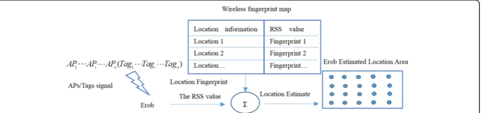
systems and storing the sampled RSS information in the database, shown in Fig.1.
The offline stage includes the following steps:
Step 1. Assign beacon nodes to the tracking area; Step 2. The tracking area is divided into many small grids (fingerprints), and the grid points (fingerprint points) are used as reference points in the tracking area;
Step 3. To store the acquired RSS into the corresponding coordinate database.
In the online stage, Erob sends the RSS signal to the ser-ver according to the RSS signal acquired at different beacon points, and the server calls the online search algorithm to estimate the position of Erob, shown in Fig.2.
The online stage includes the following steps:
Step 1. Erob enters the tracking area, and then acquires RSS values from each beacon node;
Step 2. To compare the obtained RSS values with the stored values in the database;
Step 3. To retrieve the closest location of the RSS value in the database.
3 Fingerprint database preparation 3.1 Infrastructure and experiment setting
In the WiFi fingerprint positioning research, we build a classroom with the infrastructure of WiFi and RFID.
The 1 m rear of the podium on the wall placed two APs, which identified as AP1, AP2, and each one
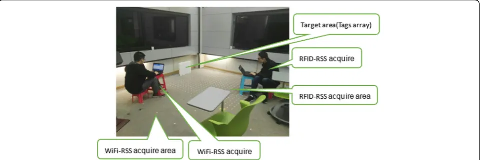
spaces 4 m, and the right side of the podium regards as the positioning target area. The experimental area was constructed by WiFi fingerprinting. The finger-print interval is 1 m, and the width of the three rows is 1 m, the experimental environment is shown in Fig. 3. Electronic tags and ground labels layout are shown in Fig. 4.
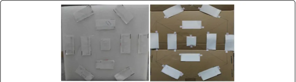
The target area is on the right of the podium, we have arranged 11 electronic tags on the whiteboard. As shown in Fig. 9, and the purpose of this design is to limit the projection area in the 0.5 m × 0.5 m = 0.25 m2. The layout of the middle tags is quadrilat-eral, which plays a certain role in correcting the hexa-gon. A central tag can be considered as the center of the projection center position. The distance from the projection area to Erob is nearest 20 cm. The ground labels’ layout area is 2 m × 2 m = 4 m2.
3.2 Experimental data acquisition
Hardware and software are indispensable part of the po-sitioning experiment, only with which can we establish the WiFi and RFID positioning system RSS database.
3.2.1 Software and hardware introduction
In the experiment, we used software and hardware equipment that includes inSSIDer; wirelessmon; 360 Mini router (APs); VM-5GA RFID module; 11 Fig. 1Based on the fingerprint positioning technology of Erob offline stage. Offline stage: When the Erob enters the wireless coverage (APs/Tags) area, which collects the RSS signal at the preset grid reference position, and processes the acquisition to establish the RSS fingerprint database
passive electronic tags; Ultra High Frequency (UHF) RFID Reader APP V2.1; Lenovo ThinkPadX220; and Erob platforms developed by ourselves, shown in Fig. 5.
3.2.2 WiFi fingerprint database preparation
In the No. 301 future classroom, we layouted two routers (AP1 and AP2), seen in Fig. 3. Erob, along the
corridor of the AP2acquired data, obtained 10 RSS (AP1
and AP2) values in each sampling point, then averaged
the RSS values.
ri¼N1
XN
j¼1
ri ð1Þ
whereiis the sampling point fingerprint number,jis the number of sampling time, and the maximum value is 10. Establishing the fingerprint database for AP1 and AP2,
and also allowing Erob to follow the AP1, the corridor
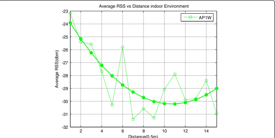
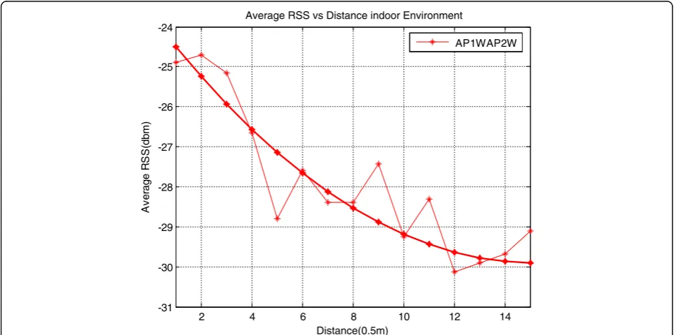
performs the same operation and builds up the database. The right corridor RSS signal changes are seen in Fig.6. The left corridor RSS signal changes are seen in Fig. 7. AP1(RSS) and AP2(RSS) means in the right (Window)
corridor are seen in Fig.8.
We also stored and processed the fingerprint database of the podium area, and through the fingerprint database analysis, we can get the maximum peak probability of the accuracy of 2 m. By improving the algorithm, we got better RSS signal characteristics and improve the po-sitioning effect, and got the maximum peak probability of the accuracy of 1.72 m.
3.2.3 RFID fingerprint database establishment
We established RFID fingerprint identification on the ground; the target area is 0.5 m × 0.5 m = 0.25 m2; the outer tags are arranged in regular hexagons; the mid-dle four tags are arranged in 0.2 m × 0.2 m; the cen-tral point is arranged with an electronic tag; and the Fig. 3Experimental environment. The No. 301 future classroom, which is a complex indoor environment
distance between the adjacent tags is 0.1 m, it is a tags array. These are seen in Fig. 9.
The data of sampling points refer to the ground la-bels, the actual acquire in strict accordance with the interval of 0.1 m distance. The fingerprint map is seen in Fig. 10. In the RSS signal acquisition area, Erob acquire signals once a second, it acquire 10 times, and each time records 11 tags. During the ex-periment, we gathered a large amount of RSS data and averaged every acquisition point value; finally, the fingerprint database is established.
The RSS sampling point distribution is seen in Fig.10. There are 11 tags in the target area, each tag needs to be collected 10 times, and a total of 110 signals are col-lected at each ground label (fingerprint point), then aver-age these values.
RSSxy¼M1 XM
i¼1 TiN1
XN
j¼1
RSSj ð2Þ
where xy is the fingerprint coordinate point; i is the number of electronic tags, and the maximum is 11; andj is the number of samples, and the maximum is 10. In this way, the RFID fingerprint database is established. Parameters are listed in Table1.
In a far distance, part of the signal is influenced by many factors. Fingerprint data RSS energy distribution is not in the central axis. RSSx5, the strongest; RSS (0y~8y) data; and RSSx5 grid offsets are 0, 0, 0, + 1,−1, −1,−2, −3, and −3, respectively. Figure 11 shows the changes in RSS with respect to the distance.
(a)
VM-5GA RFID module
(b)
Passive electronic tags
(c)
360 Mini router
(d)
Erob
Fig. 5Part of the experimental equipment.aVM-5GA RFID module—RSS signal for collecting electronic tags.bPassive electronic tags—provide RSS signal for reader.c360 Mini router—provide AP’s RSS signal for laptop.dErob—self-developed educational robot, it is a mobile platform
2 4 6 8 10 12 14
-32 -31 -30 -29 -28 -27 -26 -25 -24 -23
Distance(0.5m)
)
m
b
d(
S
S
R
e
g
ar
e
v
A
Average RSS vs Distance indoor Environment
AP1W
By analyzing the offset, we found that the signal is strong on the central axis near the target 20 cm, and it can give us a projection routing decision for Erob.
4 Experiments of fingerprint-based positioning
Erob moves near the platform, which is based on RSS energy intensity changes as navigation decisions. If
AP2-AP1≥0, Erob will move to the AP2direction and it
is very easy to enter the target area. After that, we need RFID for more accurate positioning.
4.1 Erob path-plan algorithm
There are three ways to get Erob into the RFID po-sitioning area: the first way is to enter from the left,
2 4 6 8 10 12 14
-31 -30 -29 -28 -27 -26 -25 -24 -23
Distance(0.5m)
)
m
b
d(
S
S
R
e
g
ar
e
v
A
Average RSS vs Distance indoor Environment
AP2W
Fig. 7The left corridor RSS signal changes (middle). In the left corridor, AP2RSS’s change
2 4 6 8 10 12 14
-31 -30 -29 -28 -27 -26 -25 -24
Distance(0.5m)
)
m
b
d(
S
S
R
e
g
ar
e
v
A
Average RSS vs Distance indoor Environment
AP1WAP2W
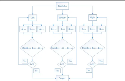
the second way is from the middle, and the third way is to enter from the right. RSS energy-enhanced depth-first algorithm is shown in Fig. 12.
The first way is arbitrary sampling point at the left of the graphic (ai, j) as entry point. Roughly, Erob
move direction is the point to the whiteboard of the wall; how to navigate Erob must be according to the RSS energy change. It is necessary to compare with RSS database points ai-1, j, ai-1, j + 1, and ai, j + 1. If
RSS ai-1, j + 1 were stronger than RSS ai-1, j and RSS
ai-1, j + 1, the decision of Erob navigation requires the
Erob move to RSS ai-1, j + 1. The next routing
deci-sion is carried out by the Erob after arrived RSS ai-1,
j + 1. Similarly, Erob will choose strong energy as the
driving direction of navigation through the compari-son of the three points’ RSS. Routing decision is shown in Fig. 13a.
The second way is arbitrary sampling point at the bottom of the graphic (ai, j) as entry point. Roughly,
Erob move direction is the point to the whiteboard of the wall, how to navigate Erob must be according to the RSS energy change. It is necessary to com-pare with RSS database’s points ai-1, j-1,ai-1, j, and
ai-1, j + 1. If RSS ai-1, j-1 were stronger than RSS ai-1, j
and RSS ai-1, j + 1, the decision of Erob navigation
re-quires the Erob move to RSS ai-1, j-1, the next
rout-ing decision is carried out by the Erob after arrived RSS ai-1, j-1. Similarly, Erob will choose strong
en-ergy as the driving direction of navigation through the comparison of the three points RSS, routing de-cision reference. The routing dede-cision is shown in Fig. 13b.
The third way is arbitrary sampling point at the right of the graphic (ai, j) as entry point. Roughly,
Erob move direction is the point to the whiteboard of the wall; how to navigate Erob must be according to the RSS energy change. It is necessary to compare with RSS database points ai-1, j, ai-1, j-1, and ai, j-1. If
RSS ai-1, j were stronger than RSS ai-1, j-1 and RSS ai,
j-1, the decision of Erob navigation requires the
robot move to RSS ai-1, j, the next routing decision
is carried out by the Erob after arrived RSS ai-1, j.
Similarly, Erob will choose strong energy as the driv-ing direction of navigation through the comparison of the three points’ RSS; routing decision is shown in Fig. 13c.
Fig. 9Projection area electronic tag layout. Tag layout structure, showing hexagons (six tags) + quads (four tags) + center points (one tag)
Fig. 10RFID fingerprint map. RFID grid provides a reference point for tags’RSS signal acquisition
Table 1RFID Fingerprint Database
RSSxy RSSx0 … RSSx5 … RSSx9 RSSx10A
RSS0y −46.1 … −41.1 −49.1 −51.2
RSS1y −51.6 … … … … …
… … … …
RSS7y −51.5 … −49.8 … −51.1 −51.7
RSS8y −52.5 … −50.6 … −51.6 −49.1
According to our routing decision algorithm idea, we establish the following matrix A.
A¼
a11 a12 … a1m
a21 a22 … a2m
⋮ ⋮ … ⋮
an1 an2 … anm
2 6 6 4
3 7 7 5
The algorithm is described below (ifn= 11,m= 9).
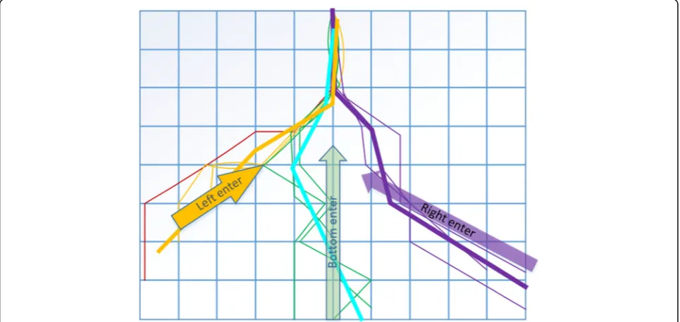
We carried out the software processing, from the left, right, and bottom any point as the entry point (each way three times); Erob movement trajectory is shown in Fig. 14.
At the same time, according to the routing deci-sion algorithm, Erob can enter from the bottom, the left, and the right, separately. In our layout of the RFID fingerprint database, we consider the robot to enter the positioning area from the above three di-rections respectively. According to the RSS energy
enhancement comparison, and manual labelling,
Erob routing direction is shown in Fig. 15.
5 Results and discussion
5.1 RSS energy distribution trend analysis
From Fig. 11, we can find that about the signal
strength distribution, Erob is much closer to the middle, RSS signal strength gets stronger, and Erob is closer to the target area. The signal strength also increased gradually, of course, during the implemen-tation of a specific test; it will receive the influence of many factors such as occlusion and reflection, resulting in unstable signal transmission and a shift in signal intensity. Fingerprint data RSS energy dis-tribution in the central axis are not all the strongest; RSS data and central axis grid offsets are 0, 0, 0, + 1, −1, −1, −2, −3, and −3, respectively.
5.2 Trajectory analysis based on RSS energy navigation algorithm
right any point(−51.79/−51.24/−49.36) enter the tar-get area; the Erob also can finally reach the point(− 41.13), which also has the ability to navigate Erob arrival in the target area and position the Erob.
5.3 The robot enters the target area trajectory from any point
Figure15presents the results of Erob into the target area (any point); Erob enters the location area from any point. According to the RSS energy distribution of the entry
point, combined with our routing algorithm, the robot can enter from any point to the target point(−41.13). It verifies the feasibility and effectiveness of our algorithm.
5.4 Positioning Erob
We navigated Erob to the 301 wisdom classroom (on the right corridor), it is about 10 m from AP1, and
set the relevant obstacle avoidance parameters, Erob according to that AP1, AP2 RSS energy changes and
makes routing decisions. The decision-making algo-rithm is driven by the energy change, driven by RSS Fig. 12RSS energy-enhanced depth-first algorithm. Erob enters the positioning area from the left, middle, and right, respectively, and makes routing decisions based on the energy changes
weak energy to RSS energy strong direction. Accord-ing to the previous experiment, we obtained the WiFi positioning accuracy can reach about 1.78 m. Using WiFi signals to positioning and guide Erob, it will enter the ground labels area.
Using our algorithm for routing decision, Erob can move to the fingerprint area, it can choose the edge
of any node into the RFID fingerprint positioning area, and through the experiment, we can get the tra-jectory of Erob movement. In the algorithm design, we set the RFID ground acquisition tags for the max-imum value of n= 11 and m= 9, according to Erob from the left any point into the RFID positioning area, through the algorithm to perform navigation. Fig. 14Erob movement trajectory algorithm test (a,b,c). Erob enters the motion routing trajectory of the RFID positioning area from any three points: left side, bottom side, and right side.aErob enters the target area’s trajectory from left side (left). Erob enters the routing path of the positioning area from any three points on the left side.bErob enters the target area’s trajectory from bottom side (middle). Erob enters the routing path of the positioning area from any three points on the middle side.cErob enters the target area’s trajectory from right side (right). Erob enters the routing path of the positioning area from any three points on the right side
middle of the electronic tags array.
6 Conclusion
According to WiFi and RFID fingerprint fusion technolo-gies, during offline stage, we layout APs and tag array, build fingerprint maps and establish RSS offline database, respectively. During online stage, we propose a set of navi-gation and positioning based on RSS energy change algo-rithm. We have obtained an ideal positioning effect in the experiment, in the vertical axis, ensure our algorithm is very good application in the projection positioning sports decision-making. We found that the middle axis is the closest to the projection area of the three sampling points of signal is more rational, and verify our algorithm can be used in making projection positioning movement, which is suitable for the decision of Erob movement. Erob can find the target location point and can push the teaching content, smart charging, discovering clients, and providing smart services, and achieve the desired effect. Positioning accuracy reach to centimeter level (2.35 cm), it can satisfy the teaching projection application. Our future work will be more accurate positioning research; we can use more advanced positioning equipment and technical means for our later intelligent charging to provide more rational po-sitioning services.
Abbreviations
AP:Access point; Erob: Educational robot; LBSs: Location-based services; MEMS: Micro-electromechanical systems; RF: Radio frequency; RFID: Radio-frequency identification; RSS: Received signal strength; RSSI: Received signal strength indicator; WiFi: Wireless fidelity
Acknowledgements
This research was supported by the specific funding for education science research by self-determined research funds of CCNU from the colleges’basic research and operation of MOE (ccnu16JYKX005). Special thanks to Professor Xinguo Yu’s guidance, from China National Engineering Research Center for E-Learning, China. The authors thank the anonymous reviewers for their valuable comments and suggestions.
Funding
The specific funding for education science research by self-determined research funds of CCNU from the colleges’basic research and operation of MOE (ccnu16JYKX005).
Authors’contributions
WL contributed to the main idea and designed the algorithm model and experiments. XD designed and carried out the simulation and wrote the code of the simulation program. FZ established the database and collected the experiment data. YW typeset document and adjusted format. DJK checked and modified the articles. All authors read and approved the final manuscript.
References
1. T Wang, The development of robot technology. Robot39(4), 385–386 (2017) View Article Baidu Scholar
2. YC Shu, C Bo, GB Shen, CS Zhao, Magicol: indoor localization using pervasive magnetic field and opportunistic WiFi sensing. IEEE J Selected Areas Commun33(7), 1443–1457 (2015) View Article Google Scholar 3. D Alimisis, Educational robotics: open questions and new challenges.
Themes Sci Technol Educ6(1), 63–71 (2013) View Article Google Scholar 4. J Li, X Yuan, CX Zhao, JF Lu, Based on the 2D laser radar small ground
mobile robot autonomous recycling method. Robot39(5), 688–696 (2017) View Article Baidu Scholar
5. HF Li, ZH Hu, JT Liu, Enhanced geometric map: a 2D&3D hybrid city model of large scale urban environment for robot navigation. Robot38(3), 311– 321 (2016) View Article Cnki Scholar
6. P Bellavista, A Kupper, S Helal, Location-based services: back to the future. IEEE Pervasive Comput7(2), 85–89 (2008) View Article Google Scholar 7. Y Alvarez, F Las Heras, ZigBee-based sensor network for indoor location and
tracking applications. IEEE Lat. Am. Trans.14(3), 3208–3214 (2016) View Article Google Scholar
8. M Scherhäufl, M Pichler, A Stelzer, UHF RFID localization based on evaluation of backscattered tag signals. IEEE Trans. Instrum. Meas.64(11), 2889–2899 (2015) View Article Google Scholar
9. P Yang, PRLS-INVES: a general experimental investigation strategy for high accuracy and precision in passive RFID location systems. IEEE Intern Things J 2(2), 159–167 (2015) View Article Google Scholar
10. SM Huynh, D Parry, ACM Fong, J Tang, Novel RFID and ontology based home localization system for misplaced objects. IEEE Trans. Consum. Electron.60(3), 402–410 (2014) View Article Google Scholar 11. Y Zhuang, Z Syed, Y Li, NE Sheimy, Evaluation of two WiFi positioning
systems based on autonomous crowd sourcing of handheld devices for indoor navigation. IEEE Trans Mobile Comput15(8), 1982–1994 (2016) View Article Google Scholar
12. S Pack, G Park, H Ko, An SIP-based location management framework in opportunistic WiFi networks. IEEE Trans. Veh. Technol.64(11), 5269–5274 (2015) View Article Google Scholar
13. C Loyez, M Bocquet, C Lethien, N Rolland, A distributed antenna system for indoor accurate WiFi localization. IEEE Antennas Wirel Propag Lett14(5), 1184–1187 (2015) View Article Google Scholar
14. D Li, BX Zhang, C Li, A feature-scaling-based k-nearest neighbor algorithm for indoor positioning systems. IEEE Intern Things J3(4), 590–597 (2016) View Article Google Scholar
15. Z Zhang, ZB Li, SW Hu, W Wang, Mobile robot navigation method in hybrid sensor networks. Robot36(3), 316–321 (2014) View Article Cnki Scholar 16. F Lu, GH Tian, GL Liu, YH Wang, Design of composite global positioning
system for service robot based on WiFi fingerprint localization and particle filter under intelligent space. Robot38(2), 178–184 (2016) View Article Cniki Scholar