Volume 2006, Article ID 63728, Pages1–14 DOI 10.1155/WCN/2006/63728
A Power-Efficient Access Point Operation for Infrastructure
Basic Service Set in IEEE 802.11 MAC Protocol
Ye Ming Hua, Lau Chiew Tong, and Benjamin Premkumar
School of Computer Engineering, Nanyang Technological University, Nanyang Avenue, Singapore 639798
Received 19 December 2005; Revised 1 May 2006; Accepted 26 May 2006
Recommended for Publication by Vincent Lau
Infrastructure-based wireless LAN technology has been widely used in today’s personal communication environment. Power ef-ficiency and battery management have been the center of attention in the design of handheld devices with wireless LAN capa-bility. In this paper, a hybrid protocol named improved PCF operation is proposed, which intelligently chooses the access point-(AP-) assisted DCF (distributed coordinator function) and enhanced PCF (point coordinator function) transmission mechanism of IEEE 802.11 protocol in an infrastructure-based wireless LAN environment. Received signal strength indicator (RSSI) is used to determine the tradeoffbetween direct mobile-to-mobile transmission and transmission routed by AP. Based on the estimation, mobile stations can efficiently communicate directly instead of being routed through AP if they are in the vicinity of each other. Furthermore, a smart AP protocol is proposed as extension to the improved PCF operation by utilizing the historical end-to-end delay information to decide the waking up time of mobile stations. Simulation results show that using the proposed protocol, en-ergy consumption of mobile devices can be reduced at the cost of slightly longer end-to-end packet delay compared to traditional IEEE 802.11 PCF protocol. However, in a non-time-critical environment, this option can significantly prolong the operation time of mobile devices.
Copyright © 2006 Ye Ming Hua et al. This is an open access article distributed under the Creative Commons Attribution License, which permits unrestricted use, distribution, and reproduction in any medium, provided the original work is properly cited.
1. INTRODUCTION
IEEE 802.11 [1]-based wireless LAN devices are being used more and more by portable computers and handheld devices as standard configuration. These devices are often powered by batteries or depletable sources of energy to achieve mobil-ity and flexibilmobil-ity. Due to constraint of weight and volume, batteries can provide only a finite amount of energy. Exten-sive research and experiments suggest that excesExten-sive usage of the wireless interface can degrade the battery lifetime of handheld devices by a factor of 2 or 3 [2,3]. Efficient use of battery power is now a significant consideration in designing mobile devices. IEEE 802.11 specifies the PCF mode to pro-vide contention-free access which can guarantee a fair and predictable service for mobile stations. The PCF operation mode is aimed to be used for the infrastructure basic service set (BSS) that requires the presence of an AP which acts as a centralized coordinator for traffic control of all the mobile stations within its coverage area. Instead of communicating with each other directly using DCF protocol, all traffic of mo-bile stations must be routed through the AP in infrastruc-ture BSS. AP can also act as the gateway between the local
mobile network and the external network such as Internet. Our analysis shows that using IEEE 802.11 PCF protocol for the infrastructure network cannot achieve an optimal perfor-mance in such environments.
In this paper, modifications to the PCF operation of IEEE 802.11 protocol are proposed that reduce the energy con-sumption and increase the throughput. The proposed proto-col improves the mobile-to-mobile traffic in the infrastruc-ture network using DCF transmission mechanism assisted by the AP. The protocol behavior and performance of tradi-tional IEEE 802.11 PCF are analyzed first especially in an en-vironment where traffic is mostly mobile to mobile. The im-proved PCF operation is introduced to improve existing IEEE 802.11 protocol which adaptively selects between PCF and AP-assisted DCF transmission mechanism based on RSSI in-formation of mobile stations for different traffic types. A two-phase polling mechanism is proposed.
(i) The first polling phase is utilized for traffic informa-tion collecinforma-tion and downlink traffic.
(iii) The contention-free period ends when AP sends the control frame of subtype CF-end, which piggybacks the explicit transmission scheduling information for DCF transmission [4] of the packets that have been announced in the first polling phase and have not been transmitted during the two polling phases.
(iv) An AP-assisted retransmission mechanism is also pro-posed in this paper. Mobile stations can pass their un-successfully transmitted packets in direct transmission phase to AP during next polling phase and AP can help to retransmit packets to the destination mobile stations.
(v) Furthermore, historical delay information and the re-quest sending time are utilized to predict the end-to-end delay, which is then utilized to decide the waking up time of mobile stations efficiently in the proposed smart AP protocol. Stations will not wake up earlier from their power-saving state than the expected arrival time of the reply packets from the remote server in a client-server-based communication scenario.
Our proposed protocol operates in a hybrid mode by tak-ing advantage of the capability of AP and the flexibility of AP-assisted DCF operation that is capable of providing service with reduced power consumption and increased throughput. The rest of the paper is organized as follows.Section 2 briefly reviews the power-saving mechanism specified in IEEE 802.11 standard and related works that improve the AP operation.Section 3presents the proposed enhancements to IEEE 802.11 PCF protocol to achieve energy efficiency and throughput improvement.Section 4describes the simulation model and results which show the advantage of the proposed algorithm.Section 5concludes the paper.
2. RELATED WORK
IEEE 802.11 PCF protocol [1] is a centralized polling-based access mechanism that requires the presence of an AP acting as point coordinator (PC). PCF is an extension that is based on the access rules defined in DCF mode. In order to inte-grate DCF and PCF together seamlessly, transmission time is divided into superframes in PCF mode. Each superframe consists of a contention period (CP) where DCF is used and a contention-free period (CFP) where PCF is used. Once the CFP started, the AP polls each station in its polling list (the high-priority stations) to grant them opportunity to access the wireless medium. A station being polled is allowed to transmit a data frame to mobile stations or the AP. How-ever, transmission to mobile stations is not supported in the infrastructure BSS implementation. Without the knowledge of the destination’s position, it is often impossible to deliver the packets with optimal power to destinations even they are within the radio coverage area of AP. Furthermore, under infrastructure BSS mode, stations are only allowed to send packets to AP using DCF during CP.
In [5], the authors propose an adaptive control algorithm to keep the aggregate throughput of AP close to the best ca-pacity of both DCF and PCF modes based on various traffic
requests. They use throughput as the feedback indicator to determine whether current dominant access method fits the traffic pattern. The throughput in PCF mode and in DCF mode are measured periodically using an estimation algo-rithm according to current traffic condition. Based on this information, the percentage of CFP duration within a super-frame is actively controlled by AP to achieve an optimal ag-gregate throughput.
In [6], the authors propose a novel relay-enabled PCF (rPCF) to exploit the multirate capability of IEEE 802.11 WLANs. Based on the channel condition, rPCF may use mul-tihop data transmission through MAC layer relay to improve the system performance. An intermediate relay node is used to forward traffic instead of direct transmission if the links from the sender to the relay node and from the relay node to the receiver can support higher data rate than direct link. In this protocol, the AP has to monitor and maintain the connection status (e.g., reachability, connection data rate, and congestion level, etc.) between all mobile stations and this can become a large overhead. The information can also get outdated since mobile stations move constantly. Further-more since the two-hop relay transmission is used, it may increase the collision probability and the packet error rate.
The authors propose a bounded-slowdown (BSD) proto-col in [7], which is an enhancement to power-saving mode of IEEE 802.11 protocol that dynamically adapts to net-work activity. Their goal is to minimize energy while limiting the observed round-trip time (RTT) of TCP connection to (1 +p)∗Rin the existence of power-saving mode, whereR is base RTT in the absence of PSM. After sending a request at timeTrequest, the mobile device has received no response at timeTcurrent, then the network interface can go to sleep for a duration up to (Tcurrent−Trequest)∗p. In the presence of beacon interval, the mobile device has to initially stay awake for 1/pbeacon intervals after sending a request. In their ex-ample, given a 100-millisecond beacon interval andp=0.2, the network interface has to stay active for 500 milliseconds. Their protocol aims to reduce the RTT while our protocol aims to conserve energy as much as possible. In our smart AP protocol, after sending a request, mobile station will not stay active in consecutive beacon intervals unless the expected re-ply is received by AP and it only stays active in specific beacon interval based on its own calculation of expected end-to-end delay.
RSSI information of mobile stations. A direct transmission is used only if it conserves energy compared with a routed transmission. An AP-assisted retransmission mechanism is also proposed that passes the unsuccessfully delivered packets to AP to conserve energy and reduce channel collision possi-bility.
3. ENHANCED PCF OPERATION OF ACCESS POINT
In this section, detailed description as how the traditional IEEE 802.11 PCF protocol can be modified to achieve a better performance is given. The original IEEE 802.11 is analyzed to show that PCF is not suitable for the environment where most traffic is between mobile stations in an infrastructure BSS. Then our improved PCF operation is introduced, which is a hybrid protocol using AP-assisted DCF operation for mobile-to-mobile traffic in an infrastructure-based wireless LAN environment. Experiments of signal strength measure-ment are also conducted. It shows that the overheard sig-nal strength information, that is used as an important met-ric in our protocol, is sufficient to determine the tradeoff between direct and routed transmissions. Furthermore, an end-to-end delay estimation method is introduced for traf-fic between mobile stations and a remote server attached to AP through wired link. The delay estimation is used to ef-ficiently determine the waking up time of mobile stations, which reduces unnecessary energy consumption when mo-bile stations stay in idle state without transmitting or receiv-ing any data. Since the upper-layer protocol may significantly affect the delay, historical delay information is used for our estimation. Furthermore, only the stations that are expecting their reply packets in current contention-free period stay in active state, which shortens the length of the polling list of AP. This also reduces the end-to-end packet delay and increases the throughput of traffic between mobile stations and AP.
3.1. Problem analysis of IEEE 802.11 PCF
IEEE 802.11 PCF mode is a centralized polling scheme, which uses AP as a coordinator for all communications within its coverage. The benefit of using the AP is obvi-ous: it will guarantee a contention-free transmission period through the centralized polling. However, it also has the fol-lowing drawbacks in an infrastructure BSS.
(1) During each CFP, the AP will issue polls to a subset of the stations on the polling list in ascending order of association identifier (AID) value. During the CFP, if all CF frames have been delivered and all STAs on the polling list have been polled, the AP may generate one or more CF polls to any station on the polling list. However, this is often not possible when the number of mobile stations is large and the traffic intensity is high. If it is assumed that mobile stations can only be polled once during each beacon interval, the average delay between two consecutive transmissions of a mo-bile station is the length of the superframe. Although it aims to maintain fairness for all stations, the mobile
MS3
D4
AP D2
D3
MS1
MS2 D1
Figure1: Choose the transmission method based on position in-formation.
stations are expected to experience long-packet end-to-end delay if the number of stations is very large. (2) The AP serves as a bridge between the mobile stations
and the wired network (internet, etc.). Extra buffering and processing delay are expected at the AP side for the mobile-to-mobile traffic which is routed through the AP.
(3) In an infrastructure BSS, all the packets will go through the AP. This is not efficient for mobile-to-mobile com-munication.
(i) Each data packet is required to be transmitted twice: mobile → AP then AP → mobile. This increases the collision probability and also in-creases channel utilization time.
(ii) As wireless transmission is subjected to higher bit error rate (BER), two-hop transmission will en-counter a higher overall error rate than that for a single-hop transmission.
(iii) The AP will buffer packets from the source sta-tion until the time the destinasta-tion stasta-tion is polled. So data packets are expected to have longer end-to-end delay. This delay can be as long as the whole length of a superframe if AP polls the destination station earlier than the source station.
for mobile stations to maintain an acceptable signal-to-noise ratio (SNR) at AP can also be es-timated based on the RSSI information of polling message from AP, which can be used by mobile stations to dynamically adjust their transmission power to AP. According to the basic theory of ra-dio communication, the received signal strength is inversely proportional to some power of dis-tance between the sender and the receiver. To guarantee a fixed SNR at the receiver side, trans-mitted power should be adjusted proportional to Dλ(2≤λ≤4 for outdoor transmission), where Dis the distance between sender and receiver. It is assumed that the power required at mobile station 1 for direct transmission isP1→2and for the transmis-sion routed by AP isP1→AP. SoP1→AP is much larger than P1→2 as shown in (1), if D2 > D1 given that 2≤λ≤4. As in this particular example, a direct trans-mission (MS1 →MS2) is more power-efficient than the transmission routed by AP (MS1→AP→MS2),
P1→AP
(v) The transmission MS1→AP→MS2 will occupy the shared wireless channel almost twice longer than a direct transmission MS1 → MS2. Both sender and receiver have to wait longer time in an idle state, which is considered as a waste of energy.
(4) Under PCF mode, there exists an option for mobile stations to reply the contention-free poll from AP by sending a frame to other mobile stations. However, due to the lack of the position information and operat-ing state (in PS state) of destination, such transmission is not guaranteed and sometimes not even possible. So it is not actually implemented in most of the wire-less LAN devices under an infrastructure BSS setup. As shown inFigure 1, MS3 is either out of the transmis-sion range of MS1, or requires much more energy than using AP as router to forward traffic.
3.2. Proposed improved PCF operation
Based on the above analysis, modifications to the PCF are necessary to achieve higher performance. In traditional PCF protocol of IEEE 802.11, right after the beacon transmis-sion AP will poll the registered stations within the service set one by one in a round-robin fashion. Upon reception of the polling message (without payload if there is no downlink data for the specific station), the station will return its uplink packets if there is any or will return a packet without payload which indicates that it has no uplink packet. The modified version operates in two polling phases.
(1) AP will poll all stations at least once. During the first polling phase, AP follows the traditional PCF opera-tion, while stations will return the following
informa-tion of their pending traffic instead of actual data pack-ets:
(i) number of pending packets for AP;
(ii) number of pending packets for other mobile sta-tions;
(iii) the destination address of mobile stations; (iv) the location information (calculated based on
the RSSI information of the poll from AP).
So after this polling phase, all the downlink packets have been transmitted.
(2) AP will send a broadcast message to all mobile stations after the first polling, which enables those mobile sta-tions with no pending packets to or from AP and other mobile stations to switch to the power-saving state un-til next beacon period.
(3) Then AP will poll the stations that are still in the active state again.
(i) It will first poll the stations that only have pend-ing packets for AP based on the traffic announce-ments received in the last polling phase. The packet transmission procedure will be according to the original PCF mode. Upon reception of the polling message, stations will acknowledge the polling by returning their uplink packets. After the transmission, stations without any pending packets for other mobile stations can switch to the power saving state until next beacon period. (ii) If the location information of mobile stations
can be obtained from a location service [9], mo-bile stations can utilize the distance information between each other to dynamically adjust their transmission power. In case such location ser-vice is not available, mobile stations can use RSSI measurements [1,10–12] based on the overheard control frames to estimate the minimal necessary power for desired destination mobile stations. In our proposed protocol, as shown inFigure 1, MS1 has data packets for MS2. During the first polling phase, if MS1 is polled first, MS1 will an-nounce its pending data packets as a reply to the poll. MS2 can then overhear the announcement which has MS2’s AID as the destination address and calculate the RSSI from MS1. The RSSI value between MS1 and MS2 is transmitted to AP as piggyback information when MS2 is polled. If MS2 is polled first, MS2 will reply a frame with-out payload to AP since it does not have pending packets. MS1 can actively overhear the transmis-sion and transmit the RSSI value between MS1 and MS2 to AP when it is polled.
Table1: Scheduling stack.
Transmission Source Destination Number of order address address pending packets 1, 2, 3,. . . 4 bytes 4 bytes 2 bytes
different mobile stations and the traffic condition (mobile to mobile), AP will calculate the power required for routed transmission (mobile to AP to mobile) and direct trans-mission (mobile to mobile) as described previously. It will choose the transmission method based on the comparison. Stations that can only use AP to forward their mobile-to-mobile traffic (either because the source and destination are out of transmission range, or the direct transmission is not power-efficient, e.g., MS1 to MS3) will be polled by AP for their pending packet subsequently. After the transmission, stations without any pending packets for mobile stations can switch to the power-saving state until the next beacon period. After all the stations that satisfy the above-mentioned criteria have been polled, AP will signal the end of the contention-free period by transmitting a control frame of subtype CF end. If there is any mobile-to-mobile traffic pending, AP will piggyback the transmission order informa-tion [4] to schedule the AP-assisted DCF transmission period to reduce any possible collision. The transmission order in-formation as shown inTable 1includes the source and des-tination address of mobile stations, the number of pending packets, and the scheduled transmission time. The variable packet length can also be incorporated in the schedule stack. For example, if the length of a single packet is considered to be 1024 bytes, a packet with length equal to 2048 bytes is considered as two units of a packet, which are scheduled together. Stations operating in the contention period must follow the explicitly announced transmission order by AP, which can minimize the contention when multiple stations with pending packets try to access the channel simultane-ously. The detailed procedure for AP and mobile station op-eration are illustrated in Figures2and3.
(4) During the direct transmission, if a specific packet has not been correctly acknowledged by the destination, the source mobile station will transmit the packet to AP during its next polling round as its uplink packet. AP will then retransmit the packets to the destination. It operates in the following manner. Suppose that A has a series of packets to be directly transmitted to B with sequence numbers 1, 2, 3, 4 and after the trans-mission of packet 2 to B, A has not received ACK from B within the ACK timeout. In this case, the transmis-sion error is probably caused by random noise. In our proposal, A will try to retransmit packet 2 only once. If the retransmission is successful, then remaining pack-ets will be transmitted as usual. If the retransmission is not acknowledged either, A will stop the direct trans-mission and pass all the remaining packets to AP dur-ing the next polldur-ing. (In this case, the destination may be in deep fading, out of range, or subject to interfer-ence.) The detailed procedure for this mechanism is illustrated inFigure 4.
3.3. Signal strength measurement of mobile stations
In our proposed algorithm, the energy consumption of the routed transmission through AP and the direct transmission are compared based on the RSSI information between mobile stations and AP. Since we are not interested in the exact tion of mobile stations, we do not have to use complex loca-tion system such as GPS [13,14] or signal triangulation and probability-based approaches [15,16]. Mobile stations can actively measure the signal strength of other mobile stations (by overhearing their transmissions when they are polled by AP) or AP (by measuring the signal strength of AP when re-ceiving polls from AP). In this section, experimental results of RSSI measurement are given to show that in practical sce-narios, the RSSI-based method is able to provide sufficient and accurate information which can be used in our proposed algorithm to determine the tradeoffbetween direct transmis-sion and routed transmistransmis-sion.
In the experiment, we try to get the signal strength val-ues of wireless connection from a single AP which is located approximately in the center of our CeMNet Research Labo-ratory. The signal strength values have been obtained at 15 locations within CeMNet, and they are illustrated as a dot-ted line inFigure 5. The distance between consecutive loca-tions is approximately 3 meters. The laptop computer which is equipped with a wireless LAN card is placed at a higher position, so there is no significant obstacle in the line-of-sight between each testing point and the antenna of the AP. At each testing point, 100 signal strength values are collected at the intervals of 0.5 second. During the post-data process-ing, we notice that there are significant data variations at the beginning of each test. The reason for this behavior is probably that the wireless card is not in the fully working condition during the switching between idle state and pas-sive reception state [17]. So the later 80 values are used in our analysis.Figure 6shows the signal strength variation at different locations. In this figure, the relationship between the location and the received signal strength values is illus-trated clearly. Even in the indoor environment, the received signal strength changes significantly when distance between sender and receiver changes, but at a fixed location the sig-nal strength tends to remain at a rather constant level. So the source mobile station can dynamically adjust its transmission power based on the RSSI information to guarantee a constant and acceptable SNR at the destination.
3.4. Proposed smart AP protocol
AP sends polling message to all mobile stations
(first poll) Poll the next
eligible mobile station
Poll the next eligible mobile
station
AP has pending packets for current
mobile station Send the poll
without payload
No Yes downlink packetsDeliver the to the mobile
station
All mobile stations
have been polled AP sends the DTIM message to all mobile stations
All mobile stations have been polled
Mobile stations without any pending packets can switch
to PS state
Mobile stations without any pending packets can switch
to PS state AP polls mobile
stations with pending packets
only for AP
AP polls mobile stations whose mobile-to-mobile traffic can only be routed through AP
AP sends CF-end control frame with
schedule for the CP direct transmission
Figure2: AP operation procedure of the enhanced PCF protocol.
they have packets for AP or the replies from remote server are already buffered at AP and ready to be transmitted to mobile stations. Using the proposed protocol, mobile stations stay in power-saving state for a longer period of time and not all mobile stations are required to stay in active state in every beacon interval. The number of mobile stations that have to be polled by AP in every beacon interval is reduced, which reduces the end-to-end delay and increases the throughput of the traffic between AP and mobile stations.
3.4.1. Analysis of the expected reply delivery delay for
waking-up-time determination of mobile stations
In order to further extend the improved PCF operation, anal-ysis and experimental results of end-to-end delay in a
MS receives the first poll in current
beacon interval from AP
Reply their pending traffic
information
Number of pending packets for AP. Number of pending packets for other MS. The destination address of MS.
The location information.
Receive the DTIM message from AP MS currently has packets
for AP or other MS
No Yes
MS switches to PS state until next beacon interval
MS remains active for poll from AP
MS has packets
pending for AP MS receives second poll from
AP
MS has packets pending for
other MS
MS replies the poll with pending packets to AP
MS replies the poll with pending packets to other MS routed by AP
MS receives CF-end control frame
and schedule Do not have
scheduled direct transmission
Have scheduled
direct transmission
MS switches to PS state
MS remains active in CP for scheduled direct
transmission
Figure3: Mobile station operation procedure of the enhanced PCF protocol.
The major difference between improved PCF operation and smart AP protocol is the beacon transmission proce-dure. In our proposed smart AP protocol, when AP trans-mits the beacon at the beginning of each beacon interval, it also piggybacks the traffic indication message (TIM) [1] to the original beacon. The TIM is generated based on all the reply packets that have been received from the remote server by AP and have not been transmitted to mobile stations. The
MS transmits the ith packet to current destination Transmit the
next packet in buffer
Retransmitith packet
ACK ofith packet? Successfully
received Not received
Seti=i+ 1 Yes Packet has been No retransmitted? Stop the direct
transmission and buffer all remaining packets for transmission in
the next CFP
Figure4: The AP-assisted retransmission mechanism.
Testing & inspection lab 1 Antenna of AP
Polymer lab
1 15
Figure5: CeMNet floor plan with illustration of the experiment setup.
1 3 5
7 9 11
13 15
Location s in CeMN
et
100 90 80 70 60 50 40 30 20
Si
gn
al
st
re
ngth
(db)
0 20
40 60
80
Num ber o
f tes ts
Figure6: 3D Map of received signal strength variation at different locations.
So stations with pending mobile-to-mobile or mobile-to-AP traffic are still required to stay in active state and report in-formation of their pending traffic as the reply to AP’s poll using the procedure described in previous sections. Using the TIM, the stations that have transmitted requests in previous beacon intervals and still wait for their replies from the re-mote server to be received by AP have a chance of switching to PS state after reception of the beacon. Hence, these sta-tions will not be polled by AP in current beacon interval if they do not have packets pending to send. If other stations still have pending packets for these stations, the packets are transmitted to AP and buffered, which can be delivered to the destination mobile stations in the following beacon intervals by notifying them using TIM.
Based on the above description, we derive the following analysis to the expected reply delivery delay of the traffic be-tween mobile stations and the remote sever.
(1) Fixed wired line delay.
0 B D B
Figure7: Lower bound of the expected reply delivery delay time with 0< D < B.
This represents the scenario where the remote server is connected with AP through reliable connections such as LAN. It is assumed that the processing time of the request at remote server is negligible compared with the transmission delay. So the expected end-to-end (mobile to remote server) reply delivery delay is alsoD, if the propagation delay between mobile stations and AP is also neglected. However, transmission time is di-vided into a series of beacon intervals and in our pro-posed smart AP protocol, the downlink packets are de-livered during the first polling phase at the beginning of each beacon interval. To consider the lower bound of the reply delivery delay, it is assumed that AP will transmit the buffered reply to the destination immedi-ately at the beginning of a beacon interval if it has re-ceived the reply for designated destination in previous beacon interval. So the reply packets can be delivered to mobile stations in a specific beacon interval only if they have already been received by AP during previ-ous beacon interval. Furthermore, if a request packet is generated at a specific mobile station before the sta-tion is polled, the packet may be transmitted to AP in current beacon interval when the station is polled. On the other hand, if the request packet is generated after the station is polled, it has to wait until the station is polled by AP in the next beacon interval.
We can see that the length of the beacon interval (B) and the time the request is sent (T) within current beacon interval are two major factors that affect the expected reply delivery time significantly. Figures7,8, and9are used to describe the expected reply delivery delay for the fixed wired line delay scenario. Thex-axis is the request sending time within current beacon in-terval and they-axis is the expected reply delivery de-lay.
Figure8: Lower bound of the expected reply delivery delay with
B < D <2B.
(i) Delay range 0 < D < B:Figure 7can be used to describe the expected reply delivery delay at des-tination mobile station. Therefore, if a request is transmitted to AP (as a reply to AP’s poll) at time Bi+Tin current beacon intervalBiwith the length of the beacon interval equal toB, the mobile sta-tion is expected to receive the reply from the remote server in the beginning of next beacon intervalBi+1 at timeBi+1, ifT+D < B(which means that AP re-ceives the reply from remote server within beacon intervalBi). IfT+D > B(which means that AP receives the reply from remote server within bea-con intervalBi+1), the mobile station is expected to receive the reply in the beginning of next bea-con intervalBi+2 at timeBi+2. The lower bound of expected reply delivery time to destination mobile stations is described using the following equations:
delay= describe the expected reply delivery delay at des-tination mobile station. The lower bound of ex-pected reply delivery time to destination mobile stations is described using the following equations:
delay= used to describe the expected reply delivery delay at destination mobile station.
0 (k+ 1)B D B
Figure9: Lower bound of the expected reply delivery delay with
kB < D <(k+ 1)B.
Using the expected reply delivery time, the power state transition pattern of mobile stations that have transmitted the request can be easily determined. Therefore, mobile stations can decide when to switch to power-saving state and when to stay in active state to receive the buffered data from the AP based on the time they have transmitted the re-quest.
(2) Variable wired line delay.
The RTT between the AP and remote server is not a fixed value but a random value Prtt uniform-ly distributed within the range of [Delaylowbound, Delayhighbound]. This represents the scenario where the remote server is connected with AP through unreliable connection such as Internet. We provide the simula-tion results of the expected reply delivery delay with a simulation program. The simulation program uses the similar assumption that we have described previously.
Figures10,11,12,13, and14show the relationship be-tween expected reply delivery delay and request sending time. The beacon interval is 100 milliseconds in the simulation, and we simulate a scenario that there is a request every 1 mil-lisecond. The queuing time and contention within the service area are currently ignored and the transmission time between mobile stations and AP is also neglected.
0 20 40 60 80 100
Request sending time (ms) 0
Figure10: Expected reply delivery delay with delay range [0, 20].
0 20 40 60 80 100
Request sending time (ms) 0
Figure11: Expected reply delivery delay with delay range [20, 40].
0 20 40 60 80 100 Request sending time (ms)
0
Figure12: Expected reply delivery delay with delay range [20, 50].
0 20 40 60 80 100
Request sending time (ms) 0
Figure13: Expected reply delivery delay with delay range [50, 100].
have not been received by AP yet, they are instructed to switch to power-saving state using TIM by AP unless they have other mobile-to-mobile or mobile-to-AP packets wait-ing.
4. SIMULATION AND ANALYSIS
In order to verify our proposed algorithm as it is incorpo-rated into existing IEEE 802.11 protocol and provide com-parison results, we used the well-known network simulator NS-2 Version 2.1b8 [18] with contributed PCF model pro-vided by Lindgren et al. [19], which has a detailed simulation of the MAC/PHY layer characteristics and infrastructure-based operation of IEEE 802.11. We implemented our pro-posed modifications on top of the existing model. In the
0 20 40 60 80 100
Request sending time (ms) 0
Figure 14: Expected reply delivery delay with delay range [100, 150].
simulation, we set up a wireless LAN environment with AP and mobile stations. The physical layer is modeled as the 2 Mbps wireless medium as widely used in most of the IEEE 802.11 compatible devices. The physical data rate does not significantly affect the results, since the MAC-level protocol operates basically in the same way for different data rates and we only make modifications on MAC level. The simu-lation area is a flat square (500×500 m2), and the AP is a special node with infinite energy and fixed position which is located in the center (250, 250) of the simulation area. The total number of mobile stations in the simulation area is 20 and they are randomly deployed within the area. We use the constant bit rate traffic with fixed-length packet size of 1024 bytes. The beacon interval is set to be 1 second and the maximum duration of the CFP is 0.8 second for PCF mode. The default energy consumption model is described in Table 2. We assume that mobile stations use fixed en-ergy level for receiving, idle and power-saving states. The transmission power is adjustable and only applicable for data packets. As a result, mobile stations use maximum transmis-sion power (Ptransmitting) for communication during the first polling phase and control packets. Based on the estimated distance (Dest) between sender and receiver, we use (5) to obtain the minimal required energy (P) for the transmis-sion,
Table2: Energy-consumption model.
Operation mode Energy
Idle 1.15 W
Power-saving mode 0.045 W
Receiving 1.4 W
TransmittingPtransmitting
1.65 W Transmission rangeDrange
250 m
destination addresses of UDP traffic set at a remote server attached to AP. The simulation time is 200 seconds and all UDP traffic start at 7 seconds together. In the simulation, we compare the traditional IEEE 802.11 protocol with our proposed modifications: the improved PCF operation and smart AP protocol. In our protocols, the mobile stations take advantage of the AP-assisted DCF transmission mechanism for direct transmission between each other without rout-ing through AP if certain criteria are met. Mobile stations do not have to stay active in every beacon interval owing to the waking-up-time estimation and announcement of TIM through beacon transmission. In the simulation, IEEE 802.11 PCF protocol has the minimum end-to-end delay as shown inFigure 15. The average delay calculation includes stations with packets targeted for remote server and mobile stations. Suppose that a total ofNpackets have been received success-fully, then the average delay can be calculated as described by
where rev timei represents the time ith packet is success-fully received, and gen timei is the generation time of ith packet.
There are several reasons that affect the results. In IEEE 802.11 PCF, stations will stay active for the entire beacon period. After all the stations in the polling list have been polled, AP can poll any station that has downlink data pack-ets pending. Packpack-ets that are generated or received during the polling period can still be transmitted to mobile stations if the contention-free period is not over. Furthermore, in our proposed algorithm, we use two-phase polling mechanism during which the first polling period is utilized for traffic in-formation collection. So the average time that a station with pending data is polled is larger than that in the traditional IEEE 802.11 PCF protocol, especially when the number of stations in the polling list of AP is very large. Our smart AP operation has a performance gain over the optimized PCF, since an estimation of the wake up time is used to decide the stations’ power state transition. Stations only stay in active state at specific polling period during which the reply from the remote server is expected to be received. So the number of stations that wake up during each contention-free period is reduced, which reduces the length of polling list. So the av-erage time that a station with pending data is polled is less than that in the improved PCF protocol.
2 0 2 4 6 8 10 12 14 16 18 20 22 Number of AP-assisted intra-BBS connections 0.002
Figure15: Average packet end-to-end delay.
2 0 2 4 6 8 10 12 14 16 18 20 22 Number of AP-assisted intra-BBS connections 1
Figure16: Energy consumption per packet.
Energy consumed per packet is computed for each packet received at the destination, which accounts for the average energy consumed by each successfully received packet. It can be described by
energy per packet=total energy consumed
total packet received . (7)
2 0 2 4 6 8 10 12 14 16 18 20 22 Number of nodes pooled
2500 3000 3500 4000 4500 5000 5500
T
o
tal
pac
ke
ts
tr
ansmitt
ed
Smart AP operation PCF with optimization IEEE 802.11 PCF
Figure17: Total packets transmitted during the simulation time.
lifetime up to 35% in the best scenario as shown inFigure 16. Stations do not have to stay active for the entire contention-free period unless they have set up schedule with AP during the first polling period, otherwise energy is wasted since sta-tions wait in an idle state without receiving or sending any data packets. The two-hop transmission is also reduced to a single-hop direct transmission if necessary for power effi -ciency. Stations can switch to power-saving mode after re-ceiving the first poll, if they do not have packets to transmit or receive. Stations can also switch to power-saving mode af-ter the second poll, if they have finished the packets transmis-sion and no direct transmistransmis-sion (AP-assisted DCF) is sched-uled by AP. If there is only traffic between the mobile stations and remote server (number of nodes polled equals 0), the energy saving can be maximized using smart AP operation. Stations do not have to wake up earlier than the time that the expected reply reaches the access point, which shortens the time that stations wait in idle state without receiving or sending any data packets.
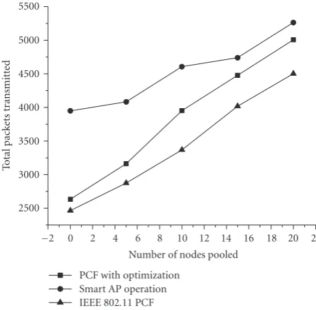
Figure 17 shows the number of data packets that has been transmitted and successfully received by the destina-tions. Since all the simulations run for the same amount of time and the traffic arrival rate, more packets transmitted suggests higher bandwidth utilization. Our proposed pro-tocol utilizes the beacon interval as long as possible for the two-phase polling if most traffic is between AP and mo-bile stations. When most traffic is between different mobile stations, our scheme will enable them to be directly trans-mitted during contention period. Furthermore, the two-hop transmission is reduced to a single-hop direct transmission without contention, which reduces the channel utilization and possibility of collision. Hence there will be more time in each contention-free period for stations that actually have
pending data packets, which increases the throughput signifi-cantly. The smart AP operation has a noticeable performance gain over the improved PCF operation mainly due to the es-timation of the waking up time through the implementation of the TIM. Mobile stations use the historical traffic infor-mation and the delay model to estimate the expected reply delivery delay. Based on the estimation and the time that a request is sent, mobile stations are able to get approximate time at which the replies are expected to be received. Using this information, stations can be instructed efficiently to stay in active state at specific contention-free period, which re-duces the energy consumption. Since stations do not have to stay in active state during every contention-free period, the length of the polling list of AP is also reduced. So there will be more time in each contention-free period for stations that actually have pending data packets, which increases the throughput significantly.
5. CONCLUSION
In this paper, enhancements to the traditional IEEE 802.11 PCF protocol are proposed. Simulation results show that us-ing the proposed protocols energy consumption of mobile devices can be reduced while the end-to-end packet delay is slightly longer than traditional IEEE 802.11 PCF protocol. The throughput is increased significantly due to the reduc-tion of channel utilizareduc-tion through the direct transmission and waking-up-time estimation. The proposed protocol is a hybrid of AP-assisted DCF and PCF operation, which is more flexible and fault-tolerant, and can be readily reverted to the traditional IEEE 802.11 protocol for compatible reason when required.
ACKNOWLEDGMENT
This work was supported by the research grant of Nanyang Technological University.
REFERENCES
[1] LAN MAN Standards Committee of the IEEE Computer Soci-ety, IEEE Std 802.11-1999, Wireless LAN Medium Access Con-trol (MAC) and Physical Layer (PHY) specifications.
[2] M. Stemm and R. H. Katz, “Measuring and reducing energy consumption of network interfaces in hand-held devices,” IE-ICE Transactions on Fundamentals of Electronics,
Communica-tions, and Computer Science, vol. E80-B, no. 8, pp. 1125–1131,
1997.
[3] L. M. Feeney, “An energy consumption model for performance analysis of routing protocols for mobile ad hoc networks,”
Mo-bile Networks and Applications, vol. 6, no. 3, pp. 239–249, 2001.
[4] M. H. Ye, C. T. Lau, and B. Premkumar, “A modified power saving mode in IEEE 802.11 distributed coordinator func-tion,”Computer Communications, vol. 28, no. 10, pp. 1214– 1224, 2005.
[5] X. J. Dong, M. Ergen, P. Varaiya, and A. Puri, “Improving the aggregate throughput of access points in IEEE 802.11 wire-less LANs,” inProceedings of the 28th Annual IEEE
Confer-ence on Local Computer Networks (LCN ’03), pp. 682–681,
[6] H. Zhu and G. Cao, “On improving the performance of IEEE 802.11 with relay-enabled PCF,”Mobile Networks and
Applica-tions, vol. 9, no. 4, pp. 423–434, 2004.
[7] R. Krashinsky and H. Balakrishnan, “Minimizing energy for wireless web access with bounded slowdown,” Wireless
Net-works, vol. 11, no. 1-2, pp. 135–148, 2005.
[8] IEEE 802.11 WG, “Draft Supplement to STANDARD FOR Telecommunications and Information Exchange Between Sys-tems - LAN/MAN Specific Requirements - Part 11: Wire-less Medium Access Control (MAC) and physical layer (PHY) specifications: Medium Access Control (MAC) Enhancements for Quality of Service (QoS),” IEEE Std 802.11e/D4.0, Novem-ber 2002.
[9] S. Meguerdichian, S. Slijepcevic, V. Karayan, and M. Potkon-jak, “Localized algorithms in wireless ad-hoc networks: loca-tion discovery and sensor exposure,” inProceedings of the 2001 ACM International Symposium on Mobile Ad Hoc
Network-ing and ComputNetwork-ing (MobiHoc ’01), pp. 106–116, Long Beach,
Calif, USA, October 2001.
[10] M. A. Youssef, A. Agrawala, and A. Udaya Shankar, “WLAN location determination via clustering and probability distri-butions,” inProceedings of the IEEE International Conference on
Pervasive Computing and Communications (PerCom ’03), Fort
Worth, Tex, USA, March 2003.
[11] P. Krishnan, A. S. Krishnakumar, W.-H. Ju, C. Mallows, and S. Ganu, “A system for LEASE: location estimation assisted by stationary emitters for indoor RF wireless networks,” in
Proceedings of IEEE INFOCOM, vol. 2, pp. 1001–1011, Hong
Kong, March 2004.
[12] V. Ramadurai and M. L. Sichitiu, “Localization in wireless sen-sor networks: a probabilistic approach,” inProceedings of the
International Conference on Wireless Networks (ICWN ’03), pp.
275–281, Las Vegas, Nev, USA, June 2003.
[13] P. Enge and P. Misra, “Special issue on global positioning sys-tem,”Proceedings of the IEEE, vol. 87, no. 1, pp. 3–15, 1999. [14] B. Hofmann-Wellenhof, H. Lichtenegger, and J. Collins,
Global Positioning System: Theory and Practice, Springer, New
York, NY, USA, 2nd edition, 1992.
[15] P. Prasithsangaree, P. Krishnamurthy, and P. K. Chrysanthis, “On indoor position location with wireless LANs,” in Proceed-ings of the 13th IEEE International Symposium on Personal,
In-door, and Mobile Radio Communications (PIMRC ’02), Lisbon,
Portugal, September 2002.
[16] S. Saha, K. Chaudhuri, D. Sanghi, and P. Bhagwat, “Location determination of a mobile device using IEEE 802.11b access point signals,” inProceedings of IEEE Wireless Communications
and Networking Conference (WCNC ’03), New Orleans, La,
USA, March 2003.
[17] T. Simunic, H. Vikalo, P. Glynn, and G. De Micheli, “Energy efficient design of portable wireless systems,” inProceedings of the International Symposium on Low Power Electronics and
De-sign (ISLPED ’00), pp. 49–54, Rapallo, Italy, July 2000.
[18] The CMU Monarch Project, “The CMU monarch project’s wireless and mobility extensions to NS,”http://www.monarch. cs.rice.edu/cmu-ns.html.
[19] A. Lindgren, A. Almquist, and O. Schel´en, “Quality of service schemes for IEEE 802.11 wireless LANs - an evaluation,”
Mo-bile Networks and Applications, vol. 8, no. 3, pp. 223–235, 2003,
special issue of the Journal of Special Topics in Mobile Net-working and Applications (MONET) on Performance Evalua-tion of QoS Architectures in Mobile Networks.
Ye Ming Hua received his B.S. degree in computer science from Fudan University, Shanghai, China, in 2002. He is currently a Ph.D. candidate in School of Computer Engineering, Nanyang Technological Uni-versity, Singapore. He is a Student Mem-ber of IEEE, and his current research in-terests are mainly in the areas of mobile ad hoc network (MANET), particularly, power-efficient MAC and routing protocols.
Lau Chiew Tong received his B.Eng. de-gree from Lakehead University, in 1983, and M.A.S. and Ph.D. degrees in electrical engineering from the University of British Columbia, in 1985 and 1990, respectively. He is currently an Associate Professor and Head of Division of Computer Communi-cations in the School of Computer Engi-neering, Nanyang Technological University, Singapore. His main research interest is in wireless communications.
Benjamin Premkumarreceived his B.S. de-gree in physics and math from Banga-lore University (India) and a Bachelor’s de-gree in electrical communication engineer-ing from the Indian Institute of Science (In-dia). He briefly worked in large communi-cation industry in Bangalore (India) in their Research and Development Division before proceeding to the US to earn his M.S. degree from North Dakota State University and his