Blind Decoding of Multiple Description Codes over
OFDM Systems via Sequential Monte Carlo
Zigang Yang
Texas Instruments Inc, 12500 TI Boulevard Dallas, MS 8653 Dallas, TX 75243, USA Email:[email protected]
Dong Guo
Department of Electrical Engineering, Columbia University, New York, NY 10027, USA Email:[email protected]
Xiaodong Wang
Department of Electrical Engineering, Columbia University, New York, NY 10027, USA Email:[email protected]
Received 1 May 2004; Revised 20 December 2004
We consider the problem of transmitting a continuous source through an OFDM system. Multiple description scalar quantization (MDSQ) is applied to the source signal, resulting in two correlated source descriptions. The two descriptions are then OFDM modulated and transmitted through two parallel frequency-selective fading channels. At the receiver, a blind turbo receiver is de-veloped for joint OFDM demodulation and MDSQ decoding. Transformation of the extrinsic information of the two descriptions are exchanged between each other to improve system performance. A blind soft-input soft-output OFDM detector is developed, which is based on the techniques of importance sampling and resampling. Such a detector is capable of exchanging the so-called extrinsic information with the other component in the above turbo receiver, and successively improving the overall receiver per-formance. Finally, we also treat channel-coded systems, and a novel blind turbo receiver is developed for joint demodulation, channel decoding, and MDSQ source decoding.
Keywords and phrases:multiple description codes, OFDM, frequency-selective fading, sequential Monte Carlo, turbo receiver.
1. INTRODUCTION
Multiple description scalar quantization (MDSQ) is a source coding technique that can exploit diversity communication systems to overcome channel impairments. An MDSQ en-coder generates multiple descriptions for a source and sends them over different channels provided by the diversity sys-tems. At the receiver, when all descriptions are received cor-rectly, a high-quality reconstruction is possible. In the event of failure of one or more of the channels, the reconstruction would still be of acceptable quality.
The problem of designing multiple description scalar quantizers is addressed in [1,2], where a theoretical perfor-mance bound is derived in [1] and practical design meth-ods are given in [2, 3]. Conventionally, MDSQ has been
This is an open access article distributed under the Creative Commons Attribution License, which permits unrestricted use, distribution, and reproduction in any medium, provided the original work is properly cited.
investigated only from the perspective of transmission over erasure channels, that is, channels which either transmit noiselessly or fail completely [1,2,4]. Recently, it was shown in [5] that an MDSQ can be used effectively for com-munication over slow-fading channels. In that system, a threshold on the channel fade values is used to determine the acceptability of the received description. The signal ceived from the bad connection is not utilized at the re-ceiver.
Diversity OFDM system
I1(j) Binary mapping
x1
n
1 a1
n OFDM
modulator
Channel 1
{h1}
AWGN S(j) MDSQ
encoder +
I2(j) Binary mapping
x2
n
2 a2
n OFDM
modulator
Channel 2
{h2}
Λ21(a1
n)
Multiple description
Λ21(I2(j))−1
2 demodulator 2OFDM
Λ12(a2n) Multiple
description
Λ12(I1(j))−1
1 demodulator 1OFDM
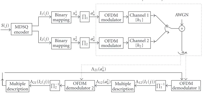
Figure1: Continuous source transmitted through a diversity OFDM system with MDSQ.
Providing high-data-rate transmission is a key objective for modern communication systems. Recently, orthogonal frequency-division multiplexing (OFDM) has received a considerable amount of interests for high-rate wireless com-munications. Because OFDM increases the symbol duration and transmitting data in parallel, it has become one of the most effective modulation techniques for combating multi-path delay spread over mobile wireless channels.
In this paper, we consider the problem of transmitting a continuous source through an OFDM system over parallel frequency-selective fading channels. The source signals are quantized and encoded by an MDSQ, resulting in two cor-related descriptions. These two descriptions are then modu-lated by OFDM and sent through two parallel fading chan-nels. At the receiver, a blind turbo receiver is developed for joint OFDM demodulation and MDSQ decoding. Transfor-mation of the extrinsic inforTransfor-mation of the two descriptions are exchanged between each other to improve system per-formance. The transformation is in terms of a transforma-tion matrix which describes the correlatransforma-tion between the two descriptions. Another novelty in this paper is the derivation of a blind detector based on a Bayesian formulation and se-quential Monte Carlo (SMC) techniques for the differentially encoded OFDM system. Being soft-input and soft-output in nature, the proposed SMC detector is capable of exchang-ing the so-called extrinsic information with the other com-ponent in the above turbo receiver, successively improving the overall receiver performance.
For a practical communication system, channel coding is usually applied to improve the reliability of the system. In this paper, we also treat a channel-coded OFDM system, where each stream of the source description is channel encoded and then OFDM modulated before being sent to the channel. At the receiver, a novel blind turbo receiver is developed for joint demodulation, channel decoding, and source decoding.
The rest of this paper is organized as follows. InSection 2, the diversity of an OFDM system with an MDSQ encoder is described. InSection 3, the turbo receiver is discussed for
the MDSQ encoded OFDM system. InSection 4, we develop an SMC algorithm for blind symbol detection of OFDM sys-tems. A turbo receiver for a channel-coded OFDM system is derived in Section 5. Simulation results are provided in Section 6, and a brief summary is given inSection 7.
2. SYSTEM DESCRIPTION
We consider transmitting a continuous source through a diversity OFDM system. The diversity of an OFDM sys-tem is made up of two N-subcarrier OFDM systems, sig-nalling through two parallel frequency-selective fading chan-nels. Such a parallel channel structure was first introduced in [9]. A block diagram of the system is shown inFigure 1. A sequence of continuous sources{S(j)}is encoded by a mul-tiple description scalar quantizer (MDSQ), resulting in two sets of equal-length indices{(I1(j),I2(j))}, where jdenotes
the sequence order. The detailed MDSQ encoder will be dis-cussed inSection 2.1. These indices can be further described in a binary sequence{(x1
n,x2n)}with the order denoted byn.
The bit interleaversπ1 andπ2 are used to reduce the
influ-ence of error bursts at the input of the MDSQ decoder. After the interleaved bits{a1
n},{a2n}are modulated by OFDM, we
use the parallel concatenated transmission scheme shown in Figure 1; that is, one description of the source is transmit-ted through one channel and the other description is trans-mitted through another channel. At the receiver, the OFDM demodulators, which will be discussed inSection 4, generate soft information, which is then exchanged between the two OFDM detectors in the form ofa prioriprobabilities of the information symbols. Next, we will focus on the structure of the MDSQ encoder and the diversity OFDM system.
2.1. Multiple description scalar quantizer 2.1.1. Multiple description scalar quantizer
for diversity on/off channels
S(j) Quantizer q(·)
l(j) Assignment α(·)
I1(j) I2(j)
Side decoder 1
Central decoder Side decoder 2
MDSQ encoder MDSQ decoder
Figure2: Conventional MDSQ in a diversity system.
1 2
3 4
5 6
7 8 (a)
1 3 2 4 5
6 7 9 8 10 11
12 13 15 14 16 17
18 19 21 20 22 (b)
1 3 5 2 6 8 10 4 7 11 12 14
9 13 16 17 19 15 18 21 23 25
20 22 26 28 30 24 27 31 32 29 33 34 (c)
1 2 3 4 · · · N−1 N
(d)
Figure3: MDSQ index assignment forR=3. A quantized source samplel(j)∈ {1, 2,. . .,N}is mapped to a pair of indices (I1(j),I2(j))⊂C
composed of its associated row and column determined by the assignmentα(·). (a) Assignment withN=8. (b) Assignment withN=22. (c) Assignment withN=34. (d) Quantizer.
in Figure 2. The channel model consists of two channels that connect the source to the destination. Either channel may be broken or lossless at any time. The encoder of an MDSQ sends information over each channel at a rate of R bits/sample. Based on the decoder structure shown in Figure 2, the objective is to design an MDSQ encoder so as to minimize the average distortion when both channels are lossless (center distortion), subject to a constraint on the av-erage distortion when only one channel is lossless (side dis-tortion).
Next, we give a brief summary of the MDSQ design presented in [2]. Denote an index set I = {1, 2,. . .,M}, where M = 2R. Let C ⊂ I×I and|C| = N ≤ M2.
The MDSQ encoder consists of anN-level quantizerq(·) : R → {1, 2,. . .,N} followed by index assignment α(·) :
{1, 2,. . .,N} → C. Note that N is both the size of C and the number of the quantization levels. Specifically, a source sampleS(j) is mapped to an indexl(j)∈ {1, 2,. . .,N}by the quantizerq(·), which is further mapped to a pair of indices (I1(j),I2(j))⊂Cby the assignmentα(·).
Assume a uniform quantizer. The main issue in MDSQ design is the choice of the set C, and the index assign-ment α(·). Following [2], an example of good assignment
forR = 3 bits/sample is illustrated inFigure 3. We assume that the cells of a quantizer are numbered 1, 2,. . .,N, in in-creasing order from left to right as shown inFigure 3d. In-tuitively, with a larger set C, center distortion will be im-proved at the expense of degraded side distortion. With the same size of the set C, the center distortion is fixed, and a diagonal-like assignment is preferred to minimize the side distortion.
2.1.2. Multiple description scalar quantizer for diversity fading channels
Although MDSQ was originally designed for diversity era-sure channels, it provides a possible solution that combines source coding and channel coding to exploit the diversity provided by communication systems. Next, we consider the application of MDSQ techniques in diversity fading chan-nels.
At the transmitter, we apply the MDSQ encoder as the conventional (cf.Figure 2). For each continuous sourceS(j), a pair of indices (I1(j),I2(j)) is generated by the MDSQ, and
is further mapped to binary bits{x1 n,x2n}
jR
n=(j−1)R+1. Recall that
OFDM modulator ai
n QPSK
mod
dki Dientialff
er-encoder S/P Zi
k
IDFT
Guard interval insertion P/S
Pulse shape filter
Channel hi(t) Front-end processing
+ AWGN
νi(t)
Yki
DFT
Guard interval removal S/P
Match filter
Figure4: Block diagram of a baseband OFDM system.
instead of using the side decoder and central decoder, a soft MDSQ decoder is employed for MDSQ over fading channels. It is assumed that a soft demodulator is available at the re-ceiver, which generates thea posteriorisymbol probability for each bitxi
n,
Λi[n]logP
xi
n=1|Y
Pxi n=0|Y
, (1)
where Ydenotes the received signal which is given by (3). Based on this posterior information, the soft MDSQ decod-ing rule is given by
ˆ
I1(j), ˆI2(j)
=arg max
(l,m)∈CP
I1(j)=l|
Λ1[n]
n
·PI2(j)=m|
Λ2[n]
n
, (2)
which maximizes the posterior probability of the indices sub-ject to a code structure constraint, that is, (I1(j),I2(j))∈C.
2.2. Signal model for diversity OFDM system
Consider an OFDM system with N-subcarriers signaling through a frequency-selective fading channel. The channel response is assumed to be constant during one symbol du-ration. The block diagram of such a system is shown in Figure 4. The diversity OFDM system is just the parallel con-catenation of combination of two such OFDM systems.
The binary information data {ai
n}n are grouped and
mapped into multiphase signals, which take values from a finite alphabet setA = {β1,. . .,β|A|}. In this paper, QPSK
modulation is employed. The QPSK signals {di
k}Nk=−02 are
differentially encoded to resolve the phase ambiguity in-herent in any blind receiver, and the output is given by Zki = Zki−1dik. These differentially encoded symbols are
then inverse DFT transformed. A guard interval is inserted to prevent possible interference between OFDM frames. After pulse shaping and parallel-to-serial conversion, the signals are transmitted through a frequency-selective fading
channel. At the receiver end, after matched-filtering and re-moving the guard interval, the sampled received signals are sent to a DFT block to demultiplex the multicarrier signals.
For theith OFDM system with proper cyclic extensions and proper sample timing, the demultiplexing sample of the kth subcarrier can be expressed as [10]
Yki=ZkiHki+Vki, k=0, 1,. . .,N−1; i=1, 2, (3)
where Vki ∼ Nc(0,σ2) is the i.i.d. complex Gaussian noise
and Hki is the channel frequency response at thekth
sub-carrier. Using the fact thatHki can be further expressed as a
DFT transformation of the channel time response, the signal model (3) becomes
Yi
k=ZkiwHf(k)hi+Vki, k=0, 1,. . .,N−1;i=1, 2, (4)
wherehi=[hi
0,hi1,. . .,hiL−1]Tcontains the time responses of
allLtaps;L = τm∆f + 1denotes the maximum number
of resolvable taps, with τm being the maximum multipath
spread and ∆f being the tone spacing of the carriers; and
wf(k) = [1,e−2πk/N,. . .,e−2πk(L−1)/N]T contains the
corre-sponding DFT coefficients.
3. TURBO RECEIVER
Y1
Figure5: Turbo decoding for multiple description over a diversity OFDM system;ΠiandΠ−1i denote the interleaver and deinterleaver, respectively, for theith description.
3.1. Blind Bayesian OFDM detector
DenoteY1 {Y1
0,Y11,. . .,YN1−1}as the received signals for
the first description. The blind Bayesian OFDM detector for the first description computes thea posterioriprobabilities of the information bits{a1
n}n,
The design of such a blind Bayesian detector will be discussed later inSection 4. For now, we assume the Bayesian detector provides us such soft information, and focus on the structure of the turbo receiver.
Thea posterioriinformation delivered by the blind detec-tor can be further expressed as
Λ1[n]=logP
a priori log-likelihood ratio (LLR) of the bit a1
n fed from
detector 2. The superscript p indicates the quantity ob-tained from the previous iteration. The first term in (6), denoted by λ1[n], represents the extrinsic information
de-livered by detector 1, based on the received signals Y1, the
structure of signal model (4), and the a priori informa-tion about all other bits{a1
l}l =n. The extrinsic information {λ1[n]}is transformed intoa prioriinformation{λ12p[n]}for
bits{a2
n}n. This information transformation procedure is
de-scribed next.
3.2. Information transformation
Assume that{ai
n}nis mapped to{xin}nafter passing through
theith deinterleaverΠ−i1, withxi
n aiπi(n). To transfer the information from detector 1 to detector 2, the following steps are required.
(1) Compute the bit probability of the deinterleaved bits
Px1 n=1
= eλ1[π1(n)]
1 +eλ1[π1(n)]. (7)
(2) Compute the probability distribution for the first in-dexI1based on the deinterleaved bit probabilities
PI1(j)=l length of each description.
(3) Compute the probability distribution for the second indexI2according to
PI2(j)=m
(4) Compute the bit probability that is associated with in-dexI2(j),
(5) Compute the log likelihood of interleaved code bit
λ12
It is important to mention here that the key step is the calcu-lation of the conditional probabilityP(I2(j)=m|I1(j)=l)
the previous section, these conditional probabilities can be easily obtained from the index assignment ruleα(·) as shown inFigure 3.
4. BLIND BAYESIAN OFDM DETECTOR
4.1. Problem statement
Denote Yi {Yi
0,Y1i,. . .,YNi−1}. The Bayesian OFDM
re-ceiver estimates thea posterioriprobabilities of the informa-tion symbols
Pdki =βl|Yi
, βl∈A;k=1,. . .,N−1, (12)
based on the received signalsYiand thea priorisymbol
prob-abilities of{dki}Nk=−11, without knowing the channel response hi. Assume the bitai
nis mapped to symboldκi(n). Based on
this symbola posterioriprobability, the LLR of the code bit as required in (5) can be computed by
Λi[n]logP
are independent of each other and havea prioridistribution p(hi) andp(Zi), respectively. The direct computation of (12)
is given by
Pdi
(4)]. Clearly, the computation in (14) involves a very high-dimensional integration which is certainly infeasible in prac-tice. Therefore, we resort to the sequential Monte Carlo method for numerical evaluation of the above multidimen-sional integration.
4.2. SMC-based blind MAP detector
Sequential Monte Carlo (SMC) is a family of methodologies that use Monte Carlo simulations to efficiently estimate the a posterioridistributions of the unknown states in a dynamic system [11,12,13]. In [14], an SMC-based blind MAP sym-bol detection algorithm for OFDM systems is proposed. This algorithm is summarized as follows.
(0) Initialization. Draw the initial samples of the chan-nel vector fromh(−j1) ∼ Nc(0,Σ−1), for j = 1,. . .,m.
All importance weights are initialized as w−(j1) = 1,
j=1,. . .,m.
The following steps are implemented at the kth recursion (k = 0,. . .,N −1) to update each weighted sample. For
j=1,. . .,m, the following hold.
(1) For eachai∈A, compute the following quantities:
µ(kj,i)=aiwHf(k)h
(3) Compute the importance weight:
w(kj)=w
(4) Update thea posteriori mean and covariance of the channel. If the imputed sampleZk(j) = aiin step (2),
(5) Perform resampling whenkis a multiple ofk0, where
k0is the resampling interval.
4.3. APP detection
The above sampling procedure generates a set of random samples {(Z(kj),wk(j))}mj=1, properly weighted with respect to
the distributionp(Zk |Yk). Based on these samples, an
on-line estimation and a delayed-weight estimation can be ob-tained straightforwardly as
Diversity OFDM system
Figure6: MDSQ over a channel-coded diversity OFDM system.
whereWk
jw (j)
k , and1(·) denotes the indicator
func-tion. Note that both of these two estimates are only approx-imations to thea posteriorisymbol probabilityP(dk =βl |
YN−1).
We next propose a novel APP estimator, where the chan-nel is estimated as a mixture vector, based on which the sym-bol APPs are then computed. Specifically, we have
ph|YN−1
The symbola posterioriprobability is then given by
Pdk=βl|YN−1
integral within (22) is an integral of a Gaussian pdf with re-spect to another Gaussian pdf. The resulting distribution is
still Gaussian, that is,
with mean and variance given, respectively, by
µk,j
Equations (24) and (25) follow from the fact that condi-tioned on the channelh,Yk andYk+1 are independent. The
symbola posteriori probability can then be computed in a close form as
Pdk=βl|YN−1
5. CHANNEL-CODED SYSTEMS
Although the MDSQ introduces some redundancy to the sys-tem, it has limited capability for error correction. In order to improve the system reliability, we next consider introducing channel coding to the proposed MDSQ system.
A block diagram of an MDSQ system over a channel-coded diversity OFDM system is shown inFigure 6. A stream of source signal{S(j)}jis MDSQ encoded, resulting in two
Inner loop
1,2 +
− Y1 OFDM
detector
{Λ1[k]} +
−
{λ1[k]} −1
1,2 Channel decoder +
−
−1 1,1
Inform transfer
{λ21[k]}
1,2 Soft CH encoder
1,1
{λ12[k]}
2,2 Soft CHencoder
2,1
Y2
OFDM detector
{Λ2[k]} +
− {λ
2[k]} −1 2,2
Channel decoder +
−
−1 2,1
Inform transfer
2,2 +
−
Inner loop
Figure7: Turbo decoding for MDSQ over a channel-coded diversity OFDM system.
indices, {b1
m,b2m}m, are then channel encoded and OFDM
modulated. There are two sets of bit interleavers in the sys-tem: one set, named{Πi,1}2i=1, is applied between the MDSQ
encoder and channel encoder; the other set, named{Πi,2}2i=1,
is applied between the channel encoder and OFDM modula-tor.
At the receiver, a novel blind iterative receiver is devel-oped for joint demodulation, channel decoding, and MDSQ decoding. The receiver structure, as shown inFigure 7, con-sists of two loops of iterative operations. For each descrip-tion, there is an inner loop (iterative procedure) for joint OFDM demodulation and channel decoding. At the outer loop, soft information of the coded bits is exchanged between the two inner loops to exploit the correlations between the two descriptions. Next, we discuss the operation of both the inner loop and the outer loop.
Inner loop: joint OFDM demodulation and channel decoding
We consider a subsystem of the original MDSQ system, which consists of the channel coding and OFDM modula-tion for only one source descripmodula-tion. Since the combina-tion of a differential encoder and OFDM system acts as an inner encoder, the above subsystem is a typical serial con-catenated code, and an iterative (turbo) receiver can be de-signed for such a system, which is denoted as the inner loop part inFigure 7. It consists of two stages: the SMC OFDM detector developed in the previous sections, followed by a MAP channel decoder [15]. The two stages are separated by a deinterleaver and an interleaver. Note that both the SMC OFDM detector and the MAP channel decoder can in-corporate the a prioriprobabilities and outputa posteriori probabilities of the code bits {ai
n}n, that is, they are
soft-input and soft-output algorithms. Based on the turbo prin-ciple, extrinsic information of the channel-coded bits can be
exchanged iteratively between the SMC OFDM detector and the MAP channel decoder to improve the performance of the subsystem.
Outer loop: exploiting the correlation between the two descriptions
the IF-T; the soft output of IF-T, however, must be trans-formed before being fed into the inner loop as a priori in-formation. Specifically, a soft channel encoder by the BCJR algorithm [15] is required to transform the soft information of the uncoded bits into the soft information of the coded bits.
6. SIMULATION RESULTS
In this section, we provide computer simulation results to illustrate the performance of the turbo receiver for MDSQ over diversity OFDM systems. In the simulations, the con-tinuous alphabet source is assumed to be uniformly dis-tributed on (−1, 1), and a uniform quantizer is applied. The source range is divided into 8, 22, and 34 intervals. Two dices are assigned to describe the source according the in-dex assignment α(·) as shown inFigure 3, where each in-dex is described with R = 3 bits. Assume the channel bandwidth for each OFDM system is divided into N =
128 subchannels. Guard interval is long enough to pro-tect the OFDM blocks from intersymbol interference due to the delay spread. The frequency-selective fading chan-nels are assumed to be uncorrelated. All L = 5 taps of the fading channel are Rayleigh distributed with the same variance, normalized such that E{L−1
n=0hn2} = 1, and
have delays τl = l/∆f, l = 0, 1,. . .,L−1. For
channel-coded systems, a rate-1/2 constraint length-5 convolutional code (with generators 23 and 35 in octal notation) is used. The interleavers are generated randomly and fixed for all simulations.
The blind SMC detector implements the algorithm de-scribed inSection 4.2. The variance of the noiseVkin (24) is
assumed known at the detector with values specified by the given SNR. The SMC algorithm drawsm=50 Monte Carlo samples at every recursion withΣ−1set to 1000IL. Two
quali-ties were used in the simulation to measure the performance of the SMC detector: bit error rate (BER) and word error rate (WER). Here, the bit error rate denotes the information bit error rate and word error rate denotes the error rate of the whole data block transferred during one symbol duration. On the other hand, mean square error (MSE) will be used to measure the performance of the whole system.
Performance of the SMC detector
The blind SMC detector, as a SISO algorithm for OFDM demodulation, is an important component of the proposed turbo receiver. Next, we illustrate the performance of the blind SMC detector. InFigure 8, the BER and WER perfor-mance is plotted. In the same figure, we also plot the known channel lower bound, where the fading coefficients are as-sumed to be perfectly known to the receiver and a MAP re-ceiver is employed to compute thea posteriorisymbol prob-abilities.
Although the SMC detector generates soft outputs in terms of the symbola posterioriprobabilities, only hard de-cisions are used in an uncoded system. However in a coded system, the channel decoder, such as a MAP decoder, requires
30 25 20 15 10 5 0
Eb/N0(dB) 10−4
10−3 10−2 10−1 100
Bi
t
er
ror
ra
te
Diff. demod. CSI bound SMC-online
SMC-delayed SMC-APP
(a)
30 25 20 15 10 5 0
Eb/N0(dB) 10−2
10−1 100
Wo
rd
er
ro
r
ra
te
Diff. demod. CSI bound SMC-online
SMC-delayed SMC-APP
(b)
Figure8: The (a) BER and (b) WER performance in an uncoded OFDM system.
soft information provided by the demodulator. Next, we examine the accurateness of the soft output provided by the SMC detector in a coded OFDM scenario. InFigure 9, the BER and WER performance for the information bits is plotted. In the same figure, the known channel lower bound is also plotted. The MAP convolutional decoder is employed in conjunction with the different detection algo-rithms. It is seen from Figure 9that the three SMC detec-tor yield different performance after the MAP decoder be-cause of the different quality of the soft information they provide. Specifically, the APP detector achieves the best per-formance.
Performance of turbo receiver for MDSQ system
14
Figure9: The (a) BER and (b) WER performance in a channel-coded OFDM system.
sdenote the quantization interval, is also plotted in a dotted line. It is seen that the BER and WER performance is signifi-cantly improved at the second iteration, that is, 15 dB better forN=8, 4 dB better forN=22 and 2 dB better forN=34. However, no significant gain is achieved by more iterations. Note that the MSEs of the turbo receivers are very close to the quantization error bound at high SNR. The quantiza-tion error bound (5.2×10⁻³) forN=8 is achieved at about
15 dB. However, much lower quantization error bounds are achieved at higher SNR by the turbo receiver withN =22 and 34, that is, 6.9×10⁻⁴forN =22 at SNR=25 dB and
2.8×10⁻⁴ forN = 34 at SNR = 30 dB. Moreover, due to
the different quantization error bounds determined byNand the BER and the WER performance achieved by the turbo re-ceiver, different MDSQ scheme should be chosen at different SNRs to minimize the MSE. For example, the MDSQ with N =8 is superior to other assignments below SNR=10 dB. However, at SNR=20 dB, the MDSQ scheme withN =22 is the best choice among the three assignments considered in this paper.
Quan8, 1st iteration Quan8, 2nd iteration Quan8, 3rd iteration
(a)
Quan8, 1st iteration Quan8, 2nd iteration Quan8, 3rd iteration
(b)
Quan8, 1st iteration Quan8, 2nd iteration Quan8, 3rd iteration Quan8, quan. error bound
(c)
30
Quan22, 1st iteration Quan22, 2nd iteration Quan22, 3rd iteration
(a)
Quan22, 1st iteration Quan22, 2nd iteration Quan22, 3rd iteration
(b)
Quan22, 1st iteration Quan22, 2nd iteration Quan22, 3rd iteration Quan22, quan. error bound
(c)
Figure11: Performance of iterative receiver for the MDSQ system withN=22. (a) BER. (b) WER. (c) MSE.
Quan34, 1st iteration Quan34, 2nd iteration Quan34, 3rd iteration
(a)
Quan34, 1st iteration Quan34, 2nd iteration Quan34, 3rd iteration
(b)
Quan34, 1st iteration Quan34, 2nd iteration Quan34, 3rd iteration Quan34, quan. error bound
(c)
10 Quan. error bound
(a)
Figure13: Performance of iterative receiver for channel coded MDSQ system, with 1 iteration for inner loop and 4 iterations for outer loop. (a) MSE. (b) BER of coded bits. (c) BER of information bits. (d) WER of coded bits. (e) WER of information bits.
Performance of turbo receiver for channel-coded MDSQ system
Finally, we consider the performance of the channel-coded MDSQ system discussed in Section 5. Performance is compared for systems with different iterative profiles. Specifically, the BER, WER, and MSE performance for the information bits and coded bits are plotted in Figures 13 and14for the 4-inner-loop and 1-outer-loop turbo receivers and the 3-inner-loop and 2-outer-loop turbo receivers, respectively. In the simulation, the source range is divided into 22 intervals as shown in Figure 3b. It is seen that the proposed turbo receiver structure can successively improve
the receiver performance through iterative processing. Moreover, the quantization error bounds are achieved at very low SNR, that is, 10 dB.
7. CONCLUSIONS
10 8 6 4 2 0
Eb/N0(dB)
−40
−20 0
Me
an
sq
u
ar
e
er
ro
r
(d
B
)
1st iteration 2nd iteration 3rd iteration Quan. error bound
(a)
10 8 6 4 2 0
Eb/N0(dB) 10−3
10−2 10−1 100
Bi
t
er
ror
ra
te
1st iteration 2nd iteration 3rd iteration (b)
10 8 6 4 2 0
Eb/N0(dB) 10−3
10−2 10−1 100
Bi
t
er
ror
ra
te
1st iteration 2nd iteration 3rd iteration (c)
10 8 6 4 2 0
Eb/N0(dB) 10−2
10−1 100
Wo
rd
er
ro
r
ra
te
1st iteration 2nd iteration 3rd iteration (d)
10 8 6 4 2 0
Eb/N0(dB) 10−2
10−1 100
Wo
rd
er
ro
r
ra
te
1st iteration 2nd iteration 3rd iteration (e)
Figure14: Performance of iterative receiver for channel-coded MDSQ system, with 2 iterations for inner loop and 3 iterations for outer loop. (a) MSE. (b) BER of coded bits. (c) BER of information bits. (d) WER of coded bits. (e) WER of information bits.
probabilities, is developed using sequential Monte Carlo (SMC) techniques. Being soft-input and soft-output in na-ture, the proposed SMC detector is capable of exchanging the so-called extrinsic information with other component in the above turbo receiver, and successively improving the overall receiver performance. Finally, we have also treated channel-coded systems, and a novel blind turbo receiver is developed for joint demodulation, channel decoding, and MDSQ decoding. Simulation results have demonstrated the effectiveness of the proposed techniques.
REFERENCES
[1] A. E. Gamal and T. Cover, “Achievable rates for multiple de-scriptions,” IEEE Trans. Inform. Theory, vol. 28, no. 6, pp. 851–857, 1982.
[2] V. Vaishampayan, “Design of multiple description scalar quantizers,” IEEE Trans. Inform. Theory, vol. 39, no. 3, pp. 821–834, 1993.
Multimedia and Expo (ICME ’02), vol. 1, pp. 261–264, Lau-sanne, Switzerland, August 2002.
[4] L. Ozarow, “On a source coding problem with two transmit-ters and three receivers,” Bell Labs Technical Journal, vol. 59, no. 10, pp. 1909–1921, 1980.
[5] S.-M. Yang and V. Vaishampayan, “Low-delay communica-tion for Rayleigh fading channels: an applicacommunica-tion of the multi-ple description quantizer,”IEEE Trans. Commun., vol. 43, no. 11, pp. 2771–2783, 1995.
[6] J. Barros, J. Hagenauer, and N. Gortz, “Turbo cross decoding of multiple descriptions,” inProc. IEEE International Con-ference on Communications (ICC ’02), vol. 3, pp. 1398–1402, New York, NY, USA, April 2002.
[7] N. Kamaci, Y. Altunbasak, and R. Mersereau, “Multiple de-scription coding with multiple transmit and receive antennas for wireless channels: the case of digital modulation,” inIEEE Global Telecommunications Conference (GLOBECOM ’01), pp. 3272–3276, San Antonio, Tex, USA, November 2001. [8] D. Sachs, R. Anand, and K. Ramchandran, “Wireless image
transmission using multiple-description based concatenated codes,” inProc. IEEE Data Compression Conference (DCC ’00), p. 569, Snowbird, Utah, USA, March 2000.
[9] K. Balachandran and J. Anderson, “Mismatched decod-ing of intersymbol interference usdecod-ing a parallel concatenated scheme,” IEEE J. Select. Areas Commun., vol. 16, no. 2, pp. 255–259, 1998.
[10] J.-J. van de Beek, O. Edfors, M. Sandell, S. K. Wilson, and P. O. B¨orjesson, “On channel estimation in OFDM systems,” inProc. IEEE Vehicular Technology Conference (VTC ’95), pp. 815–819, Chicago, Ill, USA, July 1995.
[11] A. Doucet, N. de Freitas, and N. Gordon, Sequential Monte Carlo in Practice, Springer-Verlag, New York, NY, USA, 2001. [12] A. Doucet, S. Godsill, and C. Andrieu, “On sequential Monte Carlo sampling methods for Bayesian filtering,”Statistics and Computing, vol. 10, no. 3, pp. 197–208, 2000.
[13] X. Wang, R. Chen, and J. Liu, “Monte Carlo signal processing for wireless communications,”Journal of VLSI Signal Process-ing, vol. 30, no. 1-3, pp. 89–105, 2002.
[14] Z. Yang and X. Wang, “A sequential Monte Carlo blind re-ceiver for OFDM systems in frequency-selective fading chan-nels,”IEEE Trans. Signal Processing, vol. 50, no. 2, pp. 271–280, 2002.
[15] L. Bahl, J. Cocke, F. Jelinek, and J. Raviv, “Optimal decod-ing of linear codes for minimizdecod-ing symbol error rate (Cor-resp.),”IEEE Trans. Inform. Theory, vol. 20, no. 2, pp. 284–287, 1974.
Zigang Yang received the B.S. degree in electrical engineering and applied math-ematics in 1995, and the M.S. degree in electrical engineering in 1998, both from Shanghai Jiaotong University (SJTU), Shanghai, China. In 2002, she got the Ph.D. degree in electrical engineering from Texas A&M University, College Station, Texas. From 1999 till 2002, she was a Research
As-sistant with the Department of Electrical Engineering, Texas A&M University. Currently, she is working as a system engineer at Texas Instrument, Communication R&D Lab. Her research interests are in the area of statistical signal processing and its applications, pri-marily in digital communications.
Dong Guo received the B.S. degree in geophysics and computer science from China University of Mining and Technol-ogy (CUMT), Xuzhou, China, in 1993, and the M.S. degree in geophysics from the Graduate School of Research Institute of Petroleum Exploration and Development (RIPED), Beijing, China, in 1996. In 1999, he received the Ph.D. degree in applied mathematics from Beijing University,
Beijing, China. In 2004, he received a second Ph.D. degree in electrical engineering from Columbia University, New York. His research interests are in the area of statistical signal processing and communications.
Xiaodong Wang received the B.S. degree in electrical engineering and applied math-ematics (with the highest honors) from Shanghai Jiao Tong University, Shanghai, China, in 1992; the M.S. degree in electri-cal and computer engineering from Purdue University in 1995; and the Ph.D. degree in electrical engineering from Princeton Uni-versity in 1998. From July 1998 to Decem-ber 2001, he was on the faculty of the