IJEDR1602082
International Journal of Engineering Development and Research (www.ijedr.org)450
PC Based Wireless Robotic Control in Defense and
Industrial Applications
1C.Kesava Krishna, 2B.Gopi Chandra Kumar 1M.Tech student, Department of ECE, SVCE, A.P,India 2M.Tech, Assistant Professor, Department of ECE, SVCE, A.P, India.
________________________________________________________________________________________________________ Abstract - A robot can be defined as a programmable, self-controlled device consisting of electronic, electrical, or mechanical units. More generally, it is a machine that functions in place of a living agent. Robots are especially desirable for certain work functions because, unlike humans, they never get tired; they can work in physical conditions that are uncomfortable or even dangerous; they can operate in airless conditions; they do not get bored by repetition and they cannot be distracted from the task at hand. Now a day’s our government purchased with crores of rupees to buy these missile vehicles from other countries but Recently our DRDO, India Developed “The Dhanush” missile can be used as an weapon as well as for destroying land targets depending on the rangewith their multi-specialty equipment’s. The missile gives the Indian Navy and Army the capability to strike enemy targets with great precision. Here in this project, we are we are using the technology developed for the Dhanush missile to controlling the missile from base camp with computer. NASA Developed a lunar rover or Moon rover is a space exploration vehicle (rover) designed to move across the surface of the Moon. Others have been partially or fully autonomous robots. Human factors studies involving spacesuit-clad astronauts interfacing with power, telemetry, navigation, and life-support equipment and LAB on the rover. The pick and place specification for a robot contrasts with that required for existing industrial robot system, which insist on a complete specification of each motion of the robot and not simply a description of a desired goal. An important characteristic of this specification is that they are independent of the robot performing the task with 4 axis Degrees of freedom, whereas a motion specification is wedded to a specific robot.
Keywords - PC, wireless, robotic vehicle, pick and place, RF communication, solar
________________________________________________________________________________________________________ I. INTRODUCTION
A robot can be defined as a programmable and self-controlled device consisting of electronic, electrical, or mechanical units. Generally, it is a machine that functions in place of a living being. Robots are especially designed and desirable for certain work functions because, unlike humans, they never get tired; they can be work in physical conditions that are uncomfortable or even dangerous; they can operate in airless conditions; they do not get bored by repetition and they cannot be distracted from the task at hand.
Obstacle avoidance is one of the most fundamental and researched problems in the field of mobile robotics. Most obstacle avoidance algorithms uses active range sensors such as ultrasonic sensors, laser range finders and infra-red sensors. To perform obstacle avoidance, a robot needs to know the distances to objects around it. The most common method of extracting depth information from visual images is stereo-vision. Stereo vision often produces accurate depth maps.
The pick and place specification for a robot contrasts with that required for existing industrial robot system, which insist on a complete specification of each motion of the robot and not simply a description of a desired goal. An important characteristic of this specification is that they are independent of the robot performing the task, where as a motion specification is wedded to a specific robot.
i. Existing Systems:
This is not for the first time that robots are used in defense and industry. In the modern technical world we have been seeing lot of many machines with all automation in both industry and defense. Mainly in defense there have already been many huge automated weapons used to both trace/detect the presence of the terrorists and also to attack on them as well.
This project is to design and developed an intelligent robot to detect dangerous gas/smoke by using a microcontroller. So that one can detect and be alert during the hazardous situations. The robot is designed to move as per the command given by t he controller, to move in all the directions like forward, reverse, right and left.
It is designed in such a way that, the robot will switch ON the alarm unit if any gas/smoke is detected. The video and audio are monitored at the remote PC. For transmitting audio and video signals, RF camera has been used. By this concept we can clearly view what is that going on in and around the surrounding of our robotics vehicle.
ii. Proposed System:
By using all existing systems, we can implement a robotic vehicle and implement on one system. The system is made more useful by introducing artificial intelligence to it.
IJEDR1602082
International Journal of Engineering Development and Research (www.ijedr.org)451
upper elbow along with gripper, it can open and close and is used for pick and place operation. The lower and upper elbows can move 270 degrees. Still many advancements can be used in proposed system.iii. Objective of Thesis:
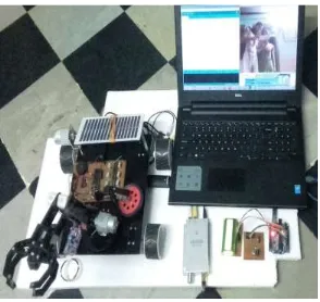
The main objective of this paper is designing and demonstrating a system that can be controlled through wireless from remote PC which can perform the tasks of obstacle avoidance, pick and place, fire detection and fire extinguisher along the wireless video transmission. This is achieved by sending and receiving signals using embedded based micro controller concept. II. BLOCK DIAGRAM:
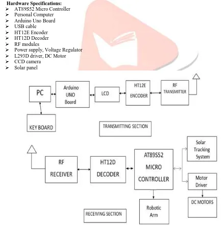
The block diagram of PC based wireless robot control is shown in the figure1. The main blocks present in the figure 1 are
1) PC
2) Arduino UNO Board 3) AT89S52 Microcontroller
4) USB type A male to USB type B male data cable 5) Encoder
6) RF transmitter 7) RF receiver 8) Decoder 9) Motor Driver 10) DC motors
11) Liquid crystal Display
In the transmitter section, a key is entered to transmit the data from remote PC to RF transmitter through USB cable. In the receiver section, RF receiver receives data and sends to the microcontroller at port 3 where the serial communication takes place. DC motors which are interfaced with L293 driver controls the robot direction.
i. Hardware Specifications: AT89S52 Micro Controller Personal Computer Arduino Uno Board USB cable
HT12E Encoder HT12D Decoder RF modules
Power supply, Voltage Regulator L293D driver, DC Motor CCD camera
Solar panel
IJEDR1602082
International Journal of Engineering Development and Research (www.ijedr.org)452
ii. Software Specifications: Keil Compiler
Language: Embedded C. Arduino CC
III. DESCRIPTION OF THE TRANSMITTER CIRCUIT DIAGRAM:
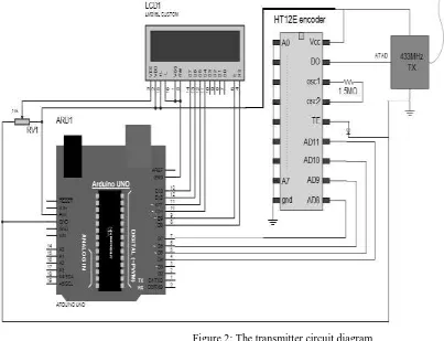
The transmitter section consists of Arduino UNO board, an LCD display, an encoder and a RF transmitter. All these components are interconnected to transmit the input signals given from the PC to the receiver module wirelessly. The UNO is a micro controller board based on the ATmega328P. It has 14 digital input/output pins (of which 6 can be used as PWM outputs), 6 analog inputs & a 16MHz quartz crystal, a USB connection, a power jack, an ICSP header and a reset button. The operating voltage of UNO board is 5V.
This Arduino board need not be connected with External supply again with the USB connection from the PC directly acts as supply for Arduino UNO board. Through USB it receives the input serially and the data is given to the LCD display and then to encoder. Here HT12E is an encoder integrated circuit of 212 series of encoders. It is mainly used in interfacing RF and infrared circuits. The chosen pair of encoder and decoder should have same number of addresses and data format. HT12E converts the parallel inputs into serial output. It encodes the 12bit parallel data in to serial for transmission through an RF transmitter. An LCD display is used in this project to show the status of the movement of the robotics vehicle RF transmitter output is up to 8mW at 433.92 MHz with a range of approximately 400 foot outdoors TWS – 434 transmitter accepts digital inputs, can operate from 1.5 to 12 volts-DC, and makes building a miniature hand-held RF transmitter easily.
Through the RF transmitter the input data is transmitted to the receiver section wirelessly, this can communicate up to 100mtrs if without any obstacles and only 50mtrs if any obstacles are present in its way. The transmitter circuit diagram is shown below in the figure 2
Figure 2: The transmitter circuit diagram IV. DESCRIPTION OF THE RECEIVER CIRCUIT DIAGRAM:
IJEDR1602082
International Journal of Engineering Development and Research (www.ijedr.org)453
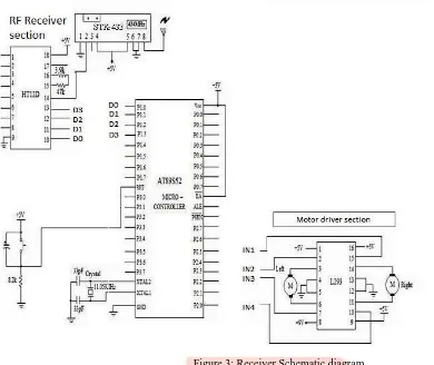
Figure 3: Receiver Schematic diagramThe HT12D is the decoder used in the receiver section and it belongs to 212 series of decoders. This series of decoders are mainly used for remote control system applications, like burglar alarm, car door controller, security system etc.
It is mainly provided to interface RF and infrared circuits. HT12D converts the serial input into parallel outputs. It decodes the serial addresses and data received by an RF receiver into parallel data and sends them to output data Pi AT89S52micro controller.
In this project, the ‘AT89S52’ is the microcontroller used and it belongs to 8051 family manufactured by Atmel AT89S52 is a low power, high performance CMOS 8-bit controller with 8K bytes of in system programmable flash memory. This microcontroller is a powerful which provides a highly flexible and cost- effective solution too many, embedded control appliances. It consists of CPU, 4 ports, RAM, EEPROM (FLASS) timer, counters, interrupts, serial port, SFRS, watch dog timer from micro controller the output is given to the motor drivers. We have 4 motor drivers.
L293DH bridge motor driver is used in receiver section. L293D is a dual H-bridge motor driver integrated circuit(IC). Motor drivers act as current amplifier since they take a low current control signal and provide a higher-current signal this higher current signal is used to drive the DC motors. L293D contains two inbuilt H-bridge driver circuits. Through this motor driver the motors are operated either in clockwise or anti clockwise. The Receiver circuit diagram is shown below in the figure 3.
IJEDR1602082
International Journal of Engineering Development and Research (www.ijedr.org)454
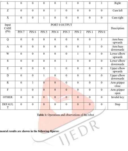
Figure 4: Flow Chart of ProgramVI. Result of the Program – Robot Directions:
The result of the project is represented in the tabular form with neat description in table 1.
Input CASE
(P2)
PORT 2 OUTPUT
Description PIN 7 PIN 6 PIN 5 PIN 4 PIN 3 PIN 2 PIN 1 PIN 0
I 0 0 0 0 1 0 1 0 Forward
J 0 0 0 0 0 1 1 0 Left
IJEDR1602082
International Journal of Engineering Development and Research (www.ijedr.org)455
L 0 0 0 0 1 0 0 1 Right
Z 0 0 0 1 0 0 0 0 Cam left
X 0 0 1 0 0 0 0 0 Cam right
Input CASE
(P0)
PORT 0 OUTPUT
Description PIN 7 PIN 6 PIN 5 PIN 4 PIN 3 PIN 2 PIN 1 PIN 0
Q 0 0 0 0 0 0 0 1 Arm base
upwards
A 0 0 0 0 0 0 1 0 Arm base
downwards
W 0 0 0 0 0 1 0 0 Lower elbow
upwards
S 0 0 0 0 1 0 0 0 Lower elbow
downwards
E 0 0 0 1 0 0 0 0 Upper elbow
upwards
D 0 0 1 0 0 0 0 0 Upper elbow
downwards
R 0 1 0 0 0 0 0 0 Arm gripper
close
F 1 0 0 0 0 0 0 0 Arm gripper
open
OTHER 0 0 0 0 0 0 0 0 Invalid key
DEFAUL T
0 0 0 0 0 0 0 0 Stop
Table 1: Operations and observations of the robot
IJEDR1602082
International Journal of Engineering Development and Research (www.ijedr.org)456
Figure 5: Transmission section through which inputs are given to robot by usingARDUINO IDE software
IJEDR1602082
International Journal of Engineering Development and Research (www.ijedr.org)457
Figure 7: LCD display in the transmitter section to describe the status of movement ofthe robotic vehicle.
IJEDR1602082
International Journal of Engineering Development and Research (www.ijedr.org)458
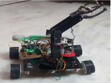
Figure 9: Robotic vehicle moving forward in direction. In the same way, the robot can alsomove in other three directions as backward, left, right.
IJEDR1602082
International Journal of Engineering Development and Research (www.ijedr.org)459
Figure 11: Robotic arm with its gripper close and open which is used to pick and placeany object.
IJEDR1602082
International Journal of Engineering Development and Research (www.ijedr.org)460
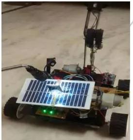
Figure 14: solar panel used in this project which is used to store solar energy with 9volts of voltage and 500mA of current. VII. CONCLUSION AND FUTURE SCOPEIn this paper, the robot is designed to move by our command and also by it own according to the command given by the program. The video and audio are monitored at the control unit. In this prototype project, we design in such a way that this robot can be moved anywhere and it can get the information of particular place. It is easy to detect any faults or dangerous in the industry. It leads easy process without interaction of human. An alerting message will be sent to a prescribed SIM using GSM module. This project is very much use full in the places where a human cannot go into the places like ground canals, smoke oriented caves and this project is very much useful in such situations.
IJEDR1602082
International Journal of Engineering Development and Research (www.ijedr.org)461
Obstacle detecting sensors to avoid physical obstacles and continue on the line. Distance sensing and position logging & transmission.
It is robust, sensitive and fast moving hence can be applied in rescue operations.
It provides for more development of applications based on android operating system such as, application based on sensors (accelerometer, gyroscope) etc.
VIII. REFERENCES:
[1]. Wireless Surveillance Robot with Motion Detection and Live Video Transmission by A.Sivasoundari, S.Kalaimani, M.Balamurugan – International Journal of Emerging Science and Engineering(IJESE) ISSN: 2319 – 6378, Volume – I, Issue – 6, April 2013.
[2]. Design and Automation of Security Management System for Industries Based On M2M Technology by Swathi Bhupatiraju, J V Subrahmanyeswara Rao – International Journal of Computer Engineering Science (IJCES) Volume 2 Issue 3 (March 2012) ISSN : 2250:3439.
[3]. Automated Advanced Industrial and Home Security Using GSM and FPGA by N.Chinthaih, K.Rajshekar – International Journal of Computer Science and Information Technologies, Vol: 2(4), 2011, 1598-1602.
[4]. Develop a Multiple Interface Based Fire Fighting Robot by Ting L.Chien, Kuo Lan Su and Sheng Ven Shiau – IEEE International Conference on Robotics and Automation, Vol: 3, PP 2084 – 2086.
[5]. John Iovine, “Robots, Androids, and Animations 12 Incredible Projects You Can Build”, Second Edition, McGraw – Hill 2002.
[6]. Mohamed Naufal bin Omar, “Pick and Place Robotics Arm Controlled by Computer”, UniveristiteknikalMalaysia, Melaka April 2007.