IJEDR1602122
International Journal of Engineering Development and Research (www.ijedr.org)689
An Experimental and Analytical study of
Cold-formed Steel Structural Members with Perforations
Subjected to Compression Loading
1 Mr. Sudhir Reddy, 2Mr. Vinay Kumar M. R, 3Prof. A. C. Sankh1,2 Reseach Students, Department of Civil Engineering 3Assistant Professor, Department of Civil Engineering
Vachana Pitamaha Dr. P. G. Halakatti College of Engg. And Technology, Vijaypur, Karnataka, INDIA
Abstract Cold formed steel sections are widely used in building structures, transportation machineries, storage racks, domestic equipment’s and other. Cold formed steel sections are widely available with difference sizes and shape. Cold formed steel sections are manufactured with difference process such as folding, press-breaking and rolling etc. The yield strength and tensile strength of the cold formed steel section increases but ductility decreases specially the corners. And the properties will diff. At the corners in CFLGSS compared to the flat steel sheet, plate and strip or base before forming. Buckling analysis plays an important role in the research and design of cold formed steel members. But we know many structural cold formed steel members are provided with perforation of diff, size and shape to accommodate electrical, plumbing, and heating services. The ultimate strength and elastic stiffness of structural members can vary with perforations made especially for fastens such as bolts, screws etc. may be neglected as perforation to make the member economical i.e. to reduce the steel the reduction in cross sectional area caused by their perforations should be taken into account for this purpose. Finite element model using ANSYS FEM Package and one can develop its accuracy will validated using experimental and theoretical results. And from numerical, experimental and theoretical investigation, the load carrying capacity of column members for diff, sizes of channel sections with various arrangements of perforations positions, subjected to compression loading will be done. Where after validations we are aiming to remove the material where the stress will be less or zero and on the same member experimental investigation will be carried out. Both the analytical and experimental load carrying capacity of the member will be compared and possible reduction in the material will be concluded.
Index Terms – Cold formed, Steel, ANSYS, LVDT, Displacement
________________________________________________________________________________________________________
I. INTRODUCTION
Cold-formed steel sections are widely used in building structures like transportation machineries, storage racks, domestic equipment’s and other. Cold formed steel sections are widely available with difference sizes and shape. Cold formed steel sections are manufactured with difference process such as folding, press-breaking and rolling etc. The yield strength and tensile strength of the cold formed steel section increases but ductility decreases specially the corners. And the properties will diff. At the corners in CFLGSS compared to the flat steel sheet, plate and strip or base before forming. Buckling analysis plays an important role in the research and design of cold formed steel members. But we know many structural cold formed steel members are provided with perforation of diff, size and shape to accommodate electrical, plumbing, and heating services. The ultimate strength and elastic stiffness of structural members can vary with perforations made especially for fastens such as bolts, screws etc. may be neglected as perforation to make the member economical i.e. to reduce the steel the reduction in cross sectional area caused by their perforations should be taken into account for this purpose. Finite element model using ANSYS FEM Package and one can develop its accuracy will validated using experimental and theoretical results. And from numerical, experimental and theoretical investigation, the load carrying capacity of column members for diff, sizes of channel sections with various arrangements of perforations positions, subjected to compression loading will be done. Where after validations we are aiming to remove the material where the stress will be less or zero and on the same member experimental investigation will be carried out. Both the analytical and experimental load carrying capacity of the member will be compared and possible reduction in the material will be concluded
II. LITERATURE REVIEW
IJEDR1602122
International Journal of Engineering Development and Research (www.ijedr.org)690
III. METHODOLOGY
The proposed research work include the exclusive analytical program in three stages namely, calculation by IS code method, analysis by ANSYS FEM software and its validation.
The proposed work include the experimental program in two stages namely making specimen and testing of full scale column section with variable in position of perforation.
The columns are tested in UTM under compression loading. The parameter studied during the test will be ultimate load carrying capacity, failure pattern and deformation laterally and longitudinally.
Then comparison between IS code method, analysis by using ANSYS and experimental will be done and finally possible position of the perforation will be concluded.
IV. EXPERIMENTAL STUDY
Thin-walled cold-formed lipped channel sections subjected to compression loading were considered in the investigation. The experimental investigation was aimed at studying the influence of perforation positions on the ultimate strength and the failure modes of lipped section columns.
a.
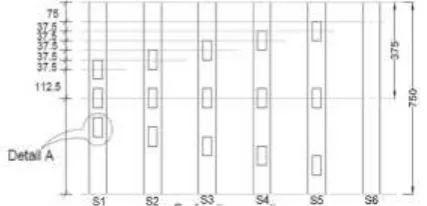
Test specimensIn order to provide sufficient stiffness and to avoid primary buckling of the stiffener itself, cross-section shape and dimensions were selected as shown in Fig. 1 and Table 1.The size of the perforations was kept constant and perforation positions were varied as illustrated in Fig.2 in order to investigate the effect of perforation positions on the ultimate strength. A channel section without perforations was also tested. The column lengths, cross- section dimensions, and perforation areas were kept constant, having a nominal thickness (0.85 mm) and specimen length (750mm). The test piece has a Flange (B) of 35mm, length (L) of 750mm, Web (H) of 75mm, fillet radius (R) of 2mm, lip (D) of 10mm and thickness (t) 0.85mm.
The ends of the test piece metal held in suitable grips in the testing machine
Figure 1 Cross-section of channel section or C-section (All dimensions are in mm)
b.
Test equipment and procedureIn this investigation specimens were tested on a Universal Testing Machine. Ends of each specimen were milled flat and parallel, to ensure that they bear directly against load bearing plates. All column specimens were loaded with displacement control at a constant rate, and a high level of accuracy of the Universal Testing Machine crosshead displacement was achieved by using linear variable displacement transducers (LVDT). Column sections bear directly on load bearing plates to represent flat-end boundary conditions, and therefore, specimen preparation and alignment can be performed without welding or the use of any attachments, then constant load is applied to the specimen and Results will be saved in 24 channel data acquisition system for decision and conclude.
IJEDR1602122
International Journal of Engineering Development and Research (www.ijedr.org)691
c.
Experimental resultThin-walled cold-formed lipped channel sections subjected to compression loading were considered in the investigation. The experimental investigation was aimed at studying the influence of perforation positions on the ultimate strength and the failure modes of lipped section columns. In order to provide sufficient stiffness and to avoid primary buckling of the stiffener itself, cross-section shape and dimensions were selected.
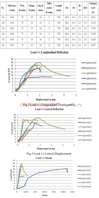
Table 1 Measured specimen dimensions and experimental results.
Fig 3 Load v/s Longitudinal Displacement
Fig 4 Load v/s Lateral Displacement
IJEDR1602122
International Journal of Engineering Development and Research (www.ijedr.org)692
Fig 6 Value of Load Corresponding to 1mm Longitudinal DeflectionFig 7 Value of Load Corresponding to 0.8mm Lateral Deflection
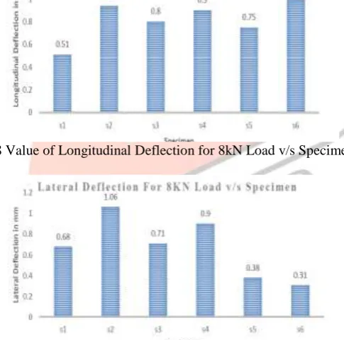
Fig 8 Value of Longitudinal Deflection for 8kN Load v/s Specimen
Fig 9 Value of Lateral Deflection for 8kN Load v/s Specimen
V. DISCUSSION OVER RESULT
Specimen S3 taken maximum load i.e. 17.85kN may be due to equally spaced perforation from both top and bottom ends. Specimen S5 shown less amount of longitudinal displacement and that is 1.6mm and specimen S6 shown less amount of
lateral displacement and that is 0.47mm
Fig. no.6 value of load corresponding to 1mm longitudinal displacement, shows that specimen S1 and specimen S3 taken almost same load but after 1mm longitudinal displacement specimen S3 taken more load compared to specimen S1 this may be due to equally spaced from ends.
Fig.no.7 value of load corresponding to 0.8mm lateral displacement shows that specimen S5 taken more load corresponding to 0.8mm lateral displacement.
IJEDR1602122
International Journal of Engineering Development and Research (www.ijedr.org)693
Fig.no.9 value of lateral deflection for 8kN load v/s specimen, shows that specimen S6 shows better perforation i.e. lessdisplacement laterally that may because of spacing of perforation is equal to perforation length.
VI. ANALYTICAL RESULT
a.
Model geometry and material modelingThe section as illustrated, modeled using symmetry of the sections, loading, and support reactions about the vertical plane. There are three main approaches that have commonly been employed to generate a finite element model in ANSYS, such as the direct generation of the finite element model, creating a solid model within ANSYS or importing a solid model created in a separate CAD system, and in this research, the solid modeling techniques were mainly employed. The ultimate stress (327 N/mm2), Poisson‘s ratio (0.3), and the actual stress–strain curve from tensile tests were used to obtain results in the numerical investigations.
b.
Element type and mesh generationThe channel sections were modeled using shell element SHELL181 which is suitable for analyzing thin to moderately thick shell structures.SHELL181 is well suited for linear, large strain, and /or large rotation non-linear applications. It Is a four nodded element with six degrees of freedom at each node: translations in the x, y, and z directions, and rotations about the x, y, and z axes, and hence, change in shell thickness is accounted for in nonlinear analyses and effects of distributed pressures. The load bearing plates were modeled using solid element SOLID45. SOLID45 is defined by eight nodes having three degrees of freedom at each node: translations in the nodal x, y, and z directions, and used for the three dimensional modeling of solid structures. Two types of meshes can be created in ANSYS such as free and mapped, based on the method of mesh generation. An adequate mesh density on contact surfaces and the section was provided to allow stresses to be distributed in a smooth fashion.
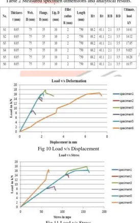
Table 2 Measured specimen dimensions and analytical results.
Fig 10 Load v/s Displacement
IJEDR1602122
International Journal of Engineering Development and Research (www.ijedr.org)694
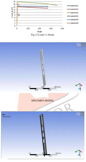
Fig 12 Load v/s StrainSPECIMEN MODEL
IJEDR1602122
International Journal of Engineering Development and Research (www.ijedr.org)695
SPECIMEN (S1) MAXIMUM PRINICIPLE STRESSSPECIMEN (S1) TOTAL DEFORMATION
VII. CONCLUSION
The results obtained from a finite element investigation into the load capacity of column members of lipped channel cross- section subjected to compression loading were compared against the failure load predicted by experimental and analytical investigations.
The buckling behavior of channel sections exhibited in the FE models was validated using experimental investigations. Experimental and numerical investigations were used to obtain a better understanding of failure mechanisms of buckling. The finite element analysis was shown to be able to closely predict the buckling behavior of the channel sections with and
with- out perforations.
The investigation showed that the ultimate load of the structure under compression greatly varied with the perforation position.
The experimental and numerical investigations showed that in the case of slender cross sections, which are substantially affected by local buckling, the incorporation of perforations in the areas near to ends has a greater weakening effect than the same perforations at other locations.
Finally, it has been shown that Finite Element Analysis can be used in predicting the ultimate strength of cold-formed steel lipped C-sections with/without perforations with a reasonable degree of confidence.
Specimen which is having perforations equally spaced from both top and bottom ends takes maximum load.
IJEDR1602122
International Journal of Engineering Development and Research (www.ijedr.org)696
REFERNCES[1] Dr.B.C. Punmia, Ashok Kumar Jain ―Design in light gauge steel book‖ British constructional steel work ssociation(BCSA), 2012,Vol 60,pp.561-603
[2] Samuel Johnson ―American institute of steel construction‖ Specification for structural steel buildings-allowable stress design and plastic design, Chicago, 1989 February 1-2006,Vol 34,pp.12
[3] Cheng Yu, Young Ben ―Thin-walled col-formed (light gauge) steel member‘s book‖2005, Vol 62, pp.610-666
[4] Yu WW John Wiley & Sons ―Cold-formed steel design‖ structural steel research group (SSRG), 2001,Vol 39,PP.962-981 [5] Rhodes J. ―Design of cold-formed steel members‖ Elsevier Applied Science; 1991,Vol 54,pp.12-45
[6] Andrei Crisan, Viorel Ungureanu, Dan Dubina ―Behavior of cold-formed steel perforated sections in compression: Part 2— numerical investigations and design consideration‖, 2012, Vol. 61, pp. 97-105.
[7] Miquel Casafont, Magdalena Pastor, Jordi Bonada, Francesc Roure, Teoman Pek ―Linear buckling analysis of perforated steel storage rack columns with the Finite Strip Method‖, 2012,Vol 61, pp. 71-85
[8] M. Dhanalakshrni and N.E.Shanmuga ―Stub Column Tests On Cold-Formed Steel Angle Sections‖, Engineering structures, Vol 39, pp.19-20.
[9] Martin MacDonald Muditha P. Kulatunga ―Finite Element Analysis of Cold- Formed Steel Structural Members with Perforations Subjected to Compression Loading‖, 2013, Vol. 17, pp. 127-139.
[10] M. Meiyalagan, M.Anbarasu, and Dr.S.Sukumar ―Investigation on Cold formed C section Long Column with Intermediate Stiffener & Corner Lips – Under Axial‖, 2010,Vol1,pp.28-41
[11] Christopher, D. M. and Schafer, B. Elastic ―Buckling of thin plates with holes in compression or bending‖, Thin Walled Structures, 2010, Vol47, pp.1597–1607.