General Concept for the Integrity of Pressurized Components
Eberhard Roos1), Karl-Heinz Herter1), Frank Otremba1) and Klaus-Jürgen Metzner 2)
1) Staatliche Materialpruefungsanstalt (MPA), University of Stuttgart, Pfaffenwaldring 32, 70569 Stuttgart, Germany 2) E.ON, Kernkraft GmbH, Tresckowstraße 5, 30457 Hannover, Germany
ABSTRACT
World wide efforts were made in the last 30 years to develop concepts to proof the integrity of pressurized compo-nents and piping systems of nuclear power plants. This includes the verification of methods to describe the load bearing ca-pacity as well as the fracture mechanics behaviour. The main topics were to demonstrate the failure behaviour of ferritic and austenitic pipes and piping components (e.g. straight pipe, pipe bend, T-joint) with and without cracks under different loading and boundary conditions. This has been investigated in numerous experimental and analytical/numerical research projects. The results of these projects were used to adjust and to verify different methodologies and leak-before-break procedures to calculate the failure loads, the respective critical crack sizes as well as the leak area and the leak rates.
In the present paper a general concept to proof the integrity of pressurized components and systems is presented ap-plicable for operational as well as for postulated loading conditions. The concept is based on the actual material characteris-tics, the actual as-built configurations and the design of the components and systems including the knowledge of possible fail-ure mechanism during operation. An important part of the assessment is the leak before break behaviour and the break preclu-sion concept. Based on essential research results the developed procedures and methodologies for the assessment of the criti-cal crack sizes as well as the criticriti-cal loading conditions are reported and discussed. The general concept based on the Basis Safety Concept to ensure the integrity of components are stated and described. In detail the following aspects have to be treated: (a) evaluation of the as-built status of quality (design, construction, material, fabrication; results of recurrent non de-structive examinations up to now, operational experience, match the requirements of the basis safety); (b) determination of the relevant loading conditions by means of in-service monitoring (monitoring of the mode of operation, the water chemistry, the mechanical and thermal stresses, the dynamic loading); (c) evaluation of the as-built status of quality with respect to the rele-vant loading conditions (stress analysis - limitation of the stresses; fatigue analysis - determine the usage factor; fracture me-chanics analysis - determination of crack growth and critical crack and loading conditions); (d) evaluation and extent of the in-service monitoring to guarantee the succeeding operation (recurrent non destructive examination - minimum detectable flaw sizes, examination area, examination intervals; leak detection system - leak area and flow rate); (e) a closed general con-cept with graduated measures (independent redundancies) by a summarising evaluation of the integrity. With these procedures and methodologies the proof of the integrity of piping components and systems, especially the leak before break and break preclusion concept used in Germany are demonstrated.
INTRODUCTION
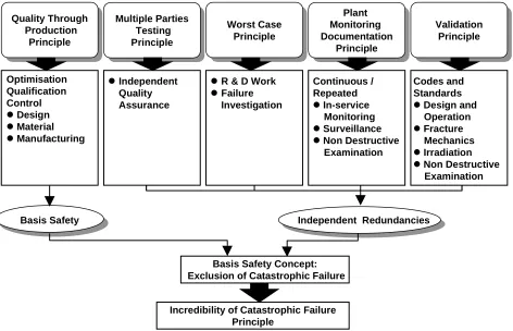
The Basis Safety Concept (BSC) in Germany has been estabished into nuclear practice since 1979, Kussmaul [1, 2]. Moreover the long term experience in the field of conventional and chemical pressure vessel and piping technology made an essential contribution. With the BSC it is essential to assess and quantify the integrity of components in a mechanis-tic/deterministic way. Through stringent measures for all safety related components and systems, in the choice of optimised materials and processing, design, stress analysis, manufacture, operation, testing and inspection, it is possible to create the necessary prerequisites for redundancies which make catastrophic failure incredible (exclusion of catastrophic failure or break preclusion concept).
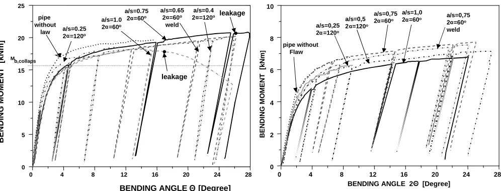
In the last 25 years world wide, Wilkowski [3], as well as within the German reactor safety research programs tre-mendous efforts were made to develop and to verify methods to describe the load bearing capacity as well as the fracture be-haviour of primary circuit piping of nuclear power plants, Kussmaul et al. [4], Bartholomé et al. [5] and Schulz [6]. Parallel to the research activities in the late 1970's in Germany the BSC, also designated as break preclusion concept, was developed and adopted in principle by the German Reactor Safety Commission (RSK guidelines 1982) [7], Fig. 1. The background of the technical understanding and basis was published in original papers by Kussmaul et al. [1, 2, 8]; by Bartholomé et al. [9]and by Schulz [6]. In Germany thus the break preclusion concept became a legal requirement. For practical reasons an upper limit of the leakage area of 0.1A (A corresponds to the cross section area of the pipe) was chosen even if break preclusion was demo-strated. In general the break preclusion concept is applied to the large diameter primary piping, Fig. 2, and to the branch con-nections down to a nominal diameter of 200 mm, Fig. 3 to 5. The concept was in principle also applied to pipes down to a
SMiRT 16, Washington DC, August 2001 Paper # 1725
nominal diameter of 50 mm, Fig. 6 and 7. (Mb,3Sm,act and Mb,3Sm,KTA - bending moment calculated on a elastic basis for a stress level according to the actual 3Sm value of the material respectively to the material data given in the KTA code; Mb,Oper.+Upset -bending moment developed by the pipe system analysis for operating plus upset conditions).
Basis Safety Concept: Exclusion of Catastrophic Failure
Plant Monitoring Documentation
Principle
Plant Monitoring Documentation
Principle
Multiple Parties Testing Principle
Multiple Parties Testing Principle
Quality Through Production
Principle
Quality Through Production
Principle
Worst Case Principle
Validation Principle
Independent Quality Assurance
R & D Work
Failure Investigation
Continuous / Repeated
In-service Monitoring
Surveillance
Non Destructive Examination
Codes and Standards
Design and Operation
Fracture Mechanics
Irradiation
Non Destructive Examination
Basis Safety Independent Redundancies
Incredibility of Catastrophic Failure Principle
Optimisation Qualification Control
Design
Material
Manufacturing
Figure 1: German Basis Safety Concept (BSC) schematically
Figure 2: Load bearing behaviour of ferritic pipes with Figure 3: Load bearing behaviour of austenitic pipes with nominal diameter DN800 (outer diameter 800 mm, nominal diameter DN300 (outer diameter 331 mm, wall thickness 47 mm) and internal pressure wall thickness 32 mm) and internal pressure 15 MPa at room temperature 16 MPa at room temperature
BENDING ANGLE [Degree]
Mb
Oper.+ Upset
B
E
N
D
IN
G
M
O
M
E
N
T
[M
N
m
]
Mb,3Sm, act.
Mb,3Sm, KTA
Mb,3Sm, act. = 11,36 MNm
Mb,3Sm, KTA = 9,85 MNm
Mb,Oper.+ Upset = 3,5 MNm pipe without flaw
a/s = 0,42
2α= 60o
a/s = 1,0 2α = 60o
0 1 2 3 4 5 6 7 8 9 10
0 2 4 6 8 10 12 14
PIPE BEND ANGLE 2 [Degree]
p
pii= 16 = 16 MPaMPa
T = 20
T = 20o o CC
Mb
Oper.+Upset
B
E
N
D
IN
G
M
O
M
E
N
T
[
k
N
m
]
0 200 400 600 1000
0 4 8 12 16 20 24 28
pipe without flaw ABV305
ABV301 a/s = 1,0 2α = 60o
ABV302 a/s = 1,0 2α = 120o
ABV304 a/s = 0,5 2α = 60o
without internal pressure
Figure 4: Load bearing behaviour of austenitic pipes with Figure 5: Load bearing behaviour of austenitic pipes with nominal diameter DN200 (outer diameter 219 mm, nominal diameter DN200 (outer diameter 219 mm wall thickness 14.2 mm) and internal pressure wall thickness 14.2 mm) and internal pressure 7 MPa at room temperature 7 MPa at room temperature
Figure 6: Load bearing behaviour of austenitic pipes with Figure 7: Load bearing behaviour of austenitic pipes with nominal diameter DN80 (outer diameter 88.9 mm, nominal diameter DN50 (outer diameter 60.3 mm wall thickness 8.8 mm) and internal pressure wall thickness 8.8 mm) and internal pressure 16 MPa at room temperature 16 MPa at room temperature
In the GRS report [10] a compilation of the individual national procedures, requirements and practices related to the integrity of light water reactor (LWR) piping with respect to the different so-called leak-before-break (LBB) concepts and philosophies is included, Table 1. Such comprehensive approaches have been developed in the United States of America (US) as the LBB concept, and in Germany, where it is known as the BSC. These concepts have been adopted also in many other countries. Although, large breaks are precluded by a successful application of the LBB concept or BSC the consequences of leakage to other components or equipment in the vicinity of the investigated components and piping system have to be as-sessed sufficiently by the design.
The aim of the following discourse is to state and describe in detail a general concept based on the Basis Safety Con-cept to ensure the integrity of components. Although the procedure may differ in a plant and component specific way, the concept can be used generally.
B
E
N
D
IN
G
M
O
M
E
N
T
[k
N
m
]
BENDING ANGLE [Degree] 0
5 10 15 20 25
0 4 8 12 16 20 24 28
Mb,collaps
leakage pipe
without law a/s=0.25
2 =120o
leakage a/s=1.0
2 =60o
a/s=0.75 2 =60o
a/s=0.65 2 =60o
weld
a/s=0.4 2 =120o
a/s=0,25 2 =120o
pipe without Flaw
0 2 4 6 8 10
0 4 8 12 16 20 24 28
BENDING ANGLE 2 [Degree]
B
E
N
D
IN
G
M
O
M
E
N
T
[k
N
m
]
a/s=0,5 2 =120o
a/s=0,75 2 =60o
a/s=1,0
2 =60o a/s=0,75 2 =60o weld 0.00E+00
2.50E+04 5.00E+04 7.50E+04 1.00E+05 1.25E+05 1.50E+05 1.75E+05 2.00E+05
0 5 10 15 20 25 30
pipe without flaw 2 = 180o
a/s=0.7 weld
2 = 180o
a/s=0.7
B
E
N
D
IN
G
M
O
M
E
N
T
[N
m
]
BEDNDING ANGLE [Grad] 0.00E+00
2.50E+04 5.00E+04 7.50E+04 1.00E+05 1.25E+05 1.50E+05 1.75E+05 2.00E+05
0 5 10 15 20 25 30 35
2 = 60o
a/s=1,0 2 = 30o
a/s=1,0
2 = 60o
a/s=0,5 pipe without
flaw
BEDNDING ANGLE [Grad]
B
E
N
D
IN
G
M
O
M
E
N
T
[N
m
Table 1: LBB application (comparison of main aspects) in different countries according to [10]
Aspects of Regulatory Position Applying in the Countries:
AC Be CS Ger Fin Fr Jap SAf SAr Sd Sp Sw UK US RF
Acceptance of LBB concept:
- generally accepted y y y y
- case-by-case basis y y y y y y y y
- under discussion y y y
Applied LBB procedure:
- NRC procedure y (y) (y) (y) (y) y y y (y)
- German procedure y (y) y (y)
- own national procedure y y y y y y y y
Reason for LBB application:
- avoidance of installation of pipe whip restraints y y y y y y y y y y y y
- compensation of low design deficiencies (type L) y y y y y
- compensation of high design deficiencies (type H) y y
Plants with LBB application:
- total number of PWR units 16 7 14 14 2 58 23 2 5 3 7 3 1 76 29
- PWR units with LBB application 4 7 4 14 0 0 10 0 2 0 6 1 1 71 4
- total number of BWR units 6 6 2 28 2 9 2 2 37 17
- BWR units with LBB application 0 6 0 1 2 0 0 1 0 2
Key:
y = yes p = partly
m = missing information (y) = based on
AC Asian Countries (China, India, Pakistan, S-Korea, Taiwan), Japan separate
Be Belgium
CS Czechoslovakia
Ger Germany
Fin Finland
Fr France
Jap Japan
SAf South Africa
SAr South America (Argentina, Brazil, Mexico)
Sd Sweden
Sp Spain
Sw Switzerland
UK United Kingdom
US USA
RF Russian Fed. plus Ukraine, Lithuania & Armenia
BASIS OF VALUATION
In Germny the principles for the safety-related requirements taken as a basis for the design of nuclear power plants (NPP), especially with respect to the state-of-the-art in science and technology, are detailed in the "Safety Criteria for Nuclear Power Plants" of the BMI [11]. The criterion 1.1 "Principles of Safety Precautions" of the BMI safety criteria requires, be-sides others, a comprehensive quality assurance for fabrication, erection and operation. The criterion 2.1 "Quality Assurance" requires, besides others, the application, preparation, and observation of design rules, material specifications, construction rules, testing and inspection as well as operating instructions and the documentation of quality assurance. The criterion 4.1 "Reactor Coolant Pressure Boundary" principally requires, besides others, the exclusion of dangerous leakage, rapidly ex-tending cracks and brittle fractures with respect to the state-of-the-art. Moreover the German Reactor Safety Commission (RSK) prepared guidelines [7] as a compilation of the safety-related requirements that, in the Commission’s opinion, have to be compiled with the design, construction and operation of a NPP with pressurised water reactor (PWR). In relation with these safety-related requirements postulated leaks and breaks for the main coolant pipes are led down as well as for the main steam and feed water piping, Fig. 8 and 9.
PREMISE TO ENSURE THE INTEGRITY OF COMPONENTS
signifi-cance (Fig. 1). This makes evident that "Basis Safety" (the "quality through production" principle) exclusively can not ensure the integrity of components for all the life time and therefore the independent redundancies are demanded in a balanced way.
Figure 8: Postulated leaks and breaks for the primary pressure boundary system (PWR) [7]
Figure 9: Postulated leaks and breaks for the primary pressure boundary system (PWR) [7]
Within the general analysis of the mechanical behaviour of the components it has to be demonstrated, that stresses (mechanical and thermal loading) as well as the usage factor (fatigue) will not exceed the limits given by the KTA safety stan-dards [12]. Furthermore already during design the supporting of piping system has to be optimised using fracture mechanics analysis taking into consideration the minimum detectable flaw sizes, the examination intervals, the specified loading condi-tions, the material characteristics and the in-service monitoring. Taking care of these aspects it is possible to demonstrate
Primary System
(RSK Guideline, Chapter 21.1, version 03/1984)
Component Leak and Break
to be postulated
Effects
➨ 0,1 A, 15 ms linear ➨ Pressure waves (RPV internals)
➨ 0,1 A, steady-state blowdown
➨ Jet forces (piping, components, building)
➨ Reaction forces (piping, components, building) Reactor Coolan Lines
➨ ≤ 2 A ➨ LOCA analysis
➨ Containment
➨ Pressure Differences (building)
➨ Qualification of I&C
Circumf. Nozzle Weld ➨ p·A·S, S=2 ➨ Stability fo the components (e.g. RPV, SG, RCP, PRZ)
RPV Leak ➨ 20 cm2 Leak ➨ RPV supporting
➨ RPV internals
➨ LOCA analysis Austenitic connection
lines with DN>200 mmm (surgeline, ECCS up to the 1st isolation)
➨ 0,1 A
➨ Jet forces (piping, components, building)
➨ Reaction forces (piping, components, building)
RPV=Reactor Pressure Vessel; SG=Steam Generator; RCP=Reactor Coolant Pump; PRZ=Pressurizer
Main Steam Line (MSL) and Main Feedwater Line (MFL)
(RSK Guideline, Chapter 21.2, version 12/1982)
Component Leak and Break
to be postulated
Effects
MSL: Between SG and MS valve assembly
➨ Leakage *), steady-state blowdown
➨ Jet and reaction forces (pipings)
MFL: Between the valve assemly outside contaiment and SG
➨ p·A·S, S=2 ➨ Stability of the SG
MSL: Behind MS valve assembly
MFL: Before the valve asssembly outside containiment
➨ 2 A ➨ Jet forces (building) **)
➨ Reaction forces (pipings, components, building) **)
➨ Pressure differences (building) **)
➨ Pressure waves (pipings, components, building; guillotine break, 15 ms, linear) MSL: Not isol. cirumferent.
break
➨ 2 A ➨ Reactivity behaviour
*) Leakage area due to a subcritical crack determined using fracture mechanics or limited to 0.1 A **) According to Basis Safety (RSK-Guidelines Chapter 4.2)
leak-before-break (LBB) behaviour for the succeeding operation. By this it can be avoided that critical crack sizes become too small due to high loads resulting from non optimised supporting of components or of the piping system and that leak flow rates are too small for detection (a critical crack size will be reached before the leak flow rates can be detected).
For components and piping systems already in operation or not fulfilling the requirements of the basis safety (BS) in a complete extent the integrity of components can be demonstrated using the independent redundancies of the BSC ("multiple party testing" principle, "worst case" principle, "continuous in-service monitoring and documentation" principle, "validation" principle) in a balanced way associated with the operational experience of the NPP’s and using the results of ongoing research programs world wide. In this way a "Quasi Basis Safety" can be demonstrated.
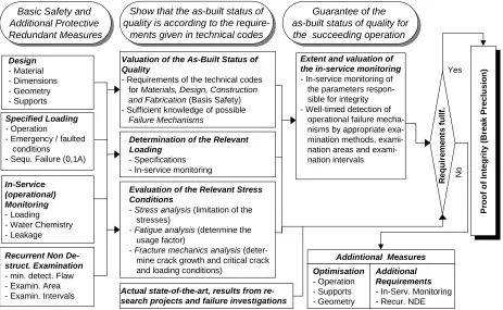
As a premise for a systematically approach to ensure the integrity of components it is indispensable to show that the as-built status of quality (design, construction, loading) is according to the requirements given in the guidelines and standards, to show that sufficient knowledge of possible failure mechanism (e.g. no inadmissible dynamic loading, no corrosion1) is available and to show that the as-built status of quality can be guaranteed for the succeeding operation.
In detail the following aspects have to be treated: (a) evaluation of the as-built status of quality (design, construction, material, fabrication; results of recurrent non destructive examinations up to now, operational experience, match the require-ments of the basis safety); (b) determination of the relevant loading conditions by means of in-service monitoring (monitoring of the mode of operation, the water chemistry, the mechanical and thermal stresses, the dynamic loading); (c) evaluation of the as-built status of quality with respect to the relevant loading conditions (stress analysis - limitation of the stresses; fatigue analysis - determine the usage factor; fracture mechanics analysis - determination of crack growth and critical crack and loading conditions); (d) evaluation and extent of the in-service monitoring to guarantee the succeeding operation (recurrent non destructive examination minimum detectable flaw sizes, examination area, examination intervals; leak detection system -leak area and flow rate); (e) proof of the closed general concept with graduated measures (independent redundancies) by a summarising evaluation of the integrity.
Figure 10: Procedure (schematically) to proof the integrity of components during design
1 It has to be demonstrated, that there is no safety relevant corrosion cracking / crack growth.
In-Service (operational) Monitoring
- Loading - Water Chemistry - Leakage
Design
- Material - Dimensions - Geometry - Supports
Specified Loading
- Operation
- Emergency / faulted conditions - Sequ. Failure (0,1A)
Recurrent Non De-struct. Examination
- min. detect. Flaw - Examin. Area - Examin. Intervals
R
e
q
u
ir
e
m
e
n
ts
f
u
ll
f.
Basic Safety and Additional Protective
Redundant Measures
Basic Safety and Additional Protective
Redundant Measures
Show that the as-built status of quality is according to the
require-ments given in technical codes
Show that the as-built status of quality is according to the
require-ments given in technical codes
Yes
N
o
P
ro
o
f
o
f
In
te
g
ri
ty
(
B
re
a
k
P
re
c
lu
s
io
n
)
Guarantee of the as-built status of quality for the succeeding operation
Guarantee of the as-built status of quality for
the succeeding operation
Optimisation
- Operation - Supports - Geometry
Additional Requirements
- In-Serv. Monitoring - Recur. NDE
Addintional Measures Valuation of the As-Built Status of
Quality
- Requirements of the technical codes for Materials, Design, Construction and Fabrication (Basis Safety) - Sufficient knowledge of possible Failure Mechanisms
Determination of the Relevant Loading
- Specifications - In-service monitoring
Evaluation of the Relevant Stress Conditions
- Stress analysis (limitation of the stresses)
- Fatigue analysis (determine the usage factor)
- Fracture mechanics analysis mine crack growth and critical crack and loading conditions)
Extent and valuation of the in-service monitoring
- In-service monitoring of the parameters sible for integrity - Well-timed detection of operational failure nisms by appropriate mination methods, nation areas and nation intervals
METHOD OF PROOF TO ENSURE THE INTEGRITY OF COMPONENTS
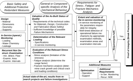
The method of proof to ensure the integrity of components differentiates between (1) the proof for components under construction (new design and new fabrication), Fig. 10, and (2) the proof for components already under operation (differenti-ates between cases where the real loading conditions are well known by in-service monitoring and cases where no in-service monitoring is available) [13], Fig. 11.
Figure 11: Procedure (schematically) to proof the integrity of components for components or systems in operation
(1) Method of proof for components under construction (new design and new fabrication)
Evaluation of the as-built status of quality
Concerning the as-built status of quality documents must be checked with respect to design, material and fabrication (it is a prerequisite that the requirements of the RSK-guidelines, of the Basis Safety and of the KTA-standards are fulfilled) and possible failure mechanism must be well known. Based on the operational experience and the state-of-the-art the failure mechanism must be identified and and their causes monitored.
Relevant loading conditions
The knowledge of the relevant loading for components under construction is of decisive importance. This forms the relevant input for stress analysis, fatigue analysis and fracture mechanics analysis. The relevant loadings (normal and upset conditions, reaction forces resulting from a 0.1A leak) are included in the load specifications of the design.
Determination of stresses and limitation
Fracture mechanics analysis must be performed for a crack size and shape safely detectable by non-destructive ex-amination (NDE) methods, Wellein [14]. Stimulated by discussion with experts and the licensing authorities as well as the results from research programs in the following the different steps for the fracture mechanics procedures to be used for the proof of integrity (break preclusion) are explained and shown in Fig. 12.
General or Component-specific Analysis of the mechanical Behaviour
General or Component-specific Analysis of the mechanical Behaviour
Basic Safety and Additional Protective Redundant Measures
Basic Safety and Additional Protective Redundant Measures
Requirements for Stress-, Fatigue- and Fracture Mechanics
Analysis
Requirements for Stress-, Fatigue- and Fracture Mechanics
Analysis
Design
- Material - Dimensions - Geometry - Supports
Recurrent Non De-struct. Examination
- min. detect. Flaw - Examin. Area - Examin. Intervals
R
e
q
u
ir
e
m
e
n
ts
f
u
ll
f.
Yes
No
Pr
o
o
f
o
f
In
te
g
ri
ty
(
B
re
a
k
Pr
e
c
lu
s
io
n
)
Optimization
- Operation - Support
Additional Requirements
- In-Ser. Monitoring - Recur. NDE
Additional Measures In-Service (operat.)
Monitoring
- Loading - Water Chemistry - Leakage
Valuation of the As-Built Status of Quality
- Requirements of the technical codes for Materials, Design, Construction and Fabrication (Basis Safety) - Sufficient knowledge of possible Failure Mechanisms
Determination of the Relevant Loading
- Specifications - In-service monitoring
Evaluation of the Relevant Stress Conditions
- Stress analysis (limitation of the stresses)
- Fatigue analysis (determine the usage factor)
- Fracture mechanics analysis mine crack growth and critical crack and loading conditions)
Extent and valuation of the in-service monitoring
- In-service monitoring of the parameters sible for integrity - Well-timed detection of operational failure chanisms by appropriate examination methods, examination areas and examination intervals
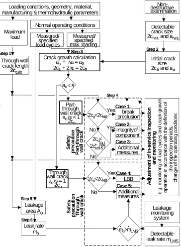
Figure 12: Fracture mechanics procedure (schematically) to proof the leak-before-break behaviour of components
Step1: Calculation of the critical crack length 2ccrit
The critical crack length of a through wall crack 2ccrit has to be calculated for the maximum loads specified for plant lifetime (plant and system specific maximum load combination for normal operating and emergency/faulted conditions). This can be achieved by limit load calculations or fracture mechanics approaches verified by component testing, Fig. 13 to 16.
Step 2: Definition of the initial crack size (crack depth aa and crack length 2ca)
Component specific definition of the initial crack size well detectable by non-destructive examination (NDE) methods (the safety factor SNDE has to be determined in a component and examination specific way) is
crack depth aa = aNDE• SNDE crack length 2ca = 2cNDE• SNDE
a a
∆
∆
o a ao
system
Step 2
Step 1 Step 3
Crack growth calculation
load
Normal operating conditions
Through wall
load cycles
wall crack
S a fe ty p re c a u ti o nYes
w a ll c ra c k P a rt -t h ro u g h S a fe ty p re ca u ti o n w a ll c ra c k T h ro u g hwall crack
Through
LBB
No
No
Yes
Step 4 Step 5Integrity
component
measures
Additional
break
preclusion
Yes
No
measures
Additional
Leakage
area A
Detectable
leak rate m
Leakage
monitoring
A d ju s tm e n t o f in -s e rv ic e i n s p e c ti o n a n d m o n it ori n g e .g. m o n ito ri ng o f lo a d c yc le s a n d c ra c k g ro w th o p e ra tio n in a c co rd a n c e w ith t h e d e fin iti o n o f ch a n g e o f th e o p e ra tin g c o n d ito n s th e in sp e c tio n p e ri o d s,2c
crack length
a + a = a
2c + 2 c = 2c
ocrit
LMS
NDE NDE
o
2c <2c
o krit2c <
o2c
*
krita
s
oo krit
2c <2c
a
o< s
o
2c
a /s < 1
o o
2c
a /s = 1
o Case 2: Case 1: Case 3: Case 4: Case 5:
Non-destructive
examination
Detectable
crack size
2c and a
Initial crack
size
2c and a
of
LMSthrough
Part-oLeak rate
m
Loading conditions, geometry, material,
manufacturing & thermohydraulic parameters
Step 3:Crack growth calculations (∆a and 2∆c)
Crack growth calculation (∆a, 2∆c) for the initial crack shape (depth aa and length 2ca) with loads specified for normal oper-ating conditions or for loads determined by in-service monitoring considering the appropriate load cycles. The final crack shape for the period to be considered will be
crack depth ao = aa + ∆a crack length 2co = 2ca + 2∆c
Crack growth shall be calculated for a period safely covering the intervals of the recurrent inspections. The concept for recur-rent inspections and in-service monitoring has to be adjusted to the results of the crack growth calculation.
Step 4: Leak before break (LBB) behaviour a) Part through crack (ao/s < 1)
The final crack length 2co must be less than the critical through wall crack length 2ccrit, that means 2co < 2ccrit. For the case 2co
≥ 2ccrit it has to be demonstrated that 2co is less than the critical crack length 2ckrit* of a part through crack with crack depth ao, that means 2co < 2ccrit*(ao/s) or it has to be demonstrated that the critical moment for the initial crack shape (aa and 2ca) is higher than the moment corresponding to the critical through wall crack length 2ccrit, that means Mcrit(aa, 2ca)/Mcrit (a/s=1) > 1.
b) Through wall crack (ao/s = 1)
The final crack length 2co must be less than the critical through wall crack length 2ccrit, that means 2co < 2ccrit.
Step 5: Calculation of leak area Ao
The leak area Ao has to be calculated for the critical through wall crack length 2ccrit (Step 1) and the crack opening (COD) for loads under normal operating conditions.
Step 6: Calculation of leak rate o
m
It has to be demonstrated that for loads under normal operating conditions the leak rate becomes o
m /S > LÜS
m (detectable leak rate by leak rate monitoring system) with a safety factor S. The safety factor S has to be determined in a component and plant specific way. The concept for recurrent inspections has to be adjusted to the results of the leak rate calculations. The leak rate shall be calculated based on a model verified by experimental data.
Figure 13: Critical crack sizes R6-method and limit load Figure 14: Critical crack sizes R6-method and limit load ! "#! $!%!&('#)+*
fl=[Rp0,2 +Rm]/2) for pipes with calculations for pipes with nominal diameter nominal diameter DN800 DN300
0 2500 5000 7500 10000 12500 15000
BE
NDI
NG
M
O
M
E
NT
[
kNm
]
0 30 60 90 120 150 180 210 240 270
CRACK ANGLE 2 [Degree]
Experimental crack initiation Experimental maximum load Plastic limit load
Initiation R6 Instability R6
Outside diameter 800 mm Wall thickness 47 mm Ferritic material
Internal pressure 13.4 Mpa Through wall crack (a/t=1.0)
0 250 500 750 1000 1250 1500
B
EN
D
IN
G
M
O
M
EN
T
[k
N
m
]
0 30 60 90 120 150 180 210 240 270 CRACK ANGLE 2 [Degree]
Initiation R6
Experimental crack initiation Experimental maximum load
Plastic limit load (PLL) σfl = (Rp0,2 + R ) / 2,4m Plastic limit load (PLL) σ
fl = Rp0,2 Plastic limit load (PLL) σ
fl = (Rp0,2 + Rm) / 2,0
Figure 9: Critical crack sizes R6-method and limit load Figure 10: Critical crack sizes R6-method and limit load . /01.2#0!/ 3!41576#8:9
fl=[Rp0,2 +Rm;=<1>7?A@(BDCFE7GDH(I!H(J K L MN1LO#N!M P!I1E7Q#K:R fl=[Rp0,2 +Rm]/2.4) for pipes with nominal diameter DN200 with nominal diameter DN50
Recurrent inspections and in-service monitoring
By recurrent inspections and in-service monitoring it has to guaranteed that assumptions of design, especially the loading conditions (mechanical, thermal, corrosive) do not change during operation. The requirements of KTA safety standard 3201.4 must be kept. In particular the in-service monitoring must detect the relevant local and global loading. The status of quality after fabrication ("Basis Safety") must be guaranteed for the succeeding operation. Therefore in-service monitoring is of decisive importance
Evaluation of the integrity
The evaluation of the integrity is based on the results of the procedure shown and thereby the following aspects are of importance: (a) monitoring of the variables responsible by sufficient detection of the causes of possible operational failure mechanisms (protective provisions, avoidance or control of the causes); (b) well-timed detection of operational failure mechanisms by appropriate examination methods, examination areas and examination intervals; (c) use of the state-of-the-art and the operational experience.
(2) Method of proof for components under operation
Evaluation of the as-built status of quality
If the requirements of the “Basis Safety” are fulfilled, the procedure is following the method of proof for components under construction. If the requirements are not fulfilled documents must be checked with respect to design, material and fabri-cation (geometry, weldment, supporting, snubbers, function of active components) and the possible failure mechanisms (mate-rial, design, processing boundary conditions, mode of operation, results of recurrent non destructive examinations, operational experience).
As a result of the evaluation of the as-built status of quality areas for additional measures concerning the loading conditions, the in-service monitoring and the recurrent non-destructive examinations can be determined.
Relevant loading conditions
It differentiates between two cases: (a) In the previous operation the relevant loading is known by in-service moni-toring, the upset conditions are lay down in the specifications of the design; (b) Relevant loading conditions are only available in the specifications of the design.
0 50 100 150 200 250 300
BE
NDI
N
G
M
O
M
E
NT
[k
N
m
]
0 30 60 90 120 150 180 210 240 270
CRACK ANGLE 2 [Degree]
Experimental crack initiation Experimental maximum load Plastic limit load
Initiation R6 Instability R6
Outside diameter 218 mm Wall thickness 14.6 mm Material: X 6 CrNiTi 18 10 Internal pressure 7 MPa Through wall crack (a/t=1.0)
0.0 2.5 5.0 7.5 10.0 12.5 15.0
B
E
N
D
IN
G
M
O
M
E
N
T
[k
N
m
]
0 30 60 90 120 150 180 210 240 270
CRACK ANGLE 2 [Degree] Experimental crack initiation Experimental maximum load Plastic limit load
Initiation R6 Instability R6
Determination of stresses and limitation
The procedure is following the one described in chapter "method of proof for components under construction" (step 1 up to step 6).
Recurrent inspections and in-service monitoring
Going beyond the procedure described in chapter "method of proof for components under construction", additional measures for recurrent inspections and in-service monitoring are necessary, especially for the case where in the previous op-eration no in-service monitoring was installed.
Evaluation of the integrity
Going beyond the procedure described in chapter "method of proof for components under construction" for the suc-ceeding operation additional measures are indispensable. It must be guaranteed by recurrent non-destructive examinations and in-service monitoring that during operation no failure mechanism will occur.
CONCLUSIONS
Based on the German Basis Safety Concept a general concept to ensure the integrity of pressurised components and systems is developed. The concept can be applied to components and systems under construction (new design) as well as to components and systems already in operation for their remaining lifetime. The calculation methods and fracture mechanics approaches are verified by numerous experimental data. The main points are on the one hand to demonstrate the actual as-built status of quality and on the other hand in-service monitoring and recurrent non-destructive examinations to guarantee the ongoing operation of the plants.
NOMENCLATURE
a = crack depth
2c = circumferential crack length
o
mS = leak rate
pi, p = pipe internal pressure
s = wall thickness
A = pipe cross section area
DN = nominal pipe diameter (outside)
Mb = pipe bending moment
Rm = tensile strength
Rp0,2 = yield strength
S = safety factor
T = temperature
= circumferential crack angle T U V
= crack growth
fl = flow stress
= pipe bending angle
REFERENCES
1. K. Kussmaul and D. Blind; "Basis Safety – A Challenge to Nuclear Technology," IAEA Spec. Meeting, Madrid, March 5.-8. 1979; Ed. in Trends in Reactor Pressure Vessel and Circuit Development by R.W. Nichols 1979, Applied Science Publishers LTD, Barking Essex, England
2. K. Kussmaul; "German Basis Safety Concept Rules Out Possibility of Catastrophic Failure," Nuclear Engineering
International 12 (1984), 41-46
3. G.M. Wilkowski, R. J. Olson and P. M. Scott; "State-of-the-Art Report on Piping Fracture Mechanics"
NUREG/CR-6540, BMI-2196, January 1998
4. K. Kussmaul, D. Blind, E. Roos and D. Sturm; “The leak before break behaviour of pipes,” VGB Kraftwerkstechnik 70, No. 7, July 1990, 465-477
5. G. Bartholomé, E. Bazant, R. Wellein, W. Stadtmüller and D. Sturm; “German experimental programs and results,”
Spec. Meeting on LBB, Lyon, France October 1995
6. H. Schulz; “Current position and actual licensing, decisions on LBB in the Federal Republic of Germany,” CSNI Report
7. Guidelines of the German Reactor Safety Commission (RSK-Guidelines) for Pressurised Water Reactors; 3rd Edition, October 14, 1981; Revised Section 21.1 of 03/1984 and Section 21.2 of 12/1982; associated general specification "Basis Safety of Pressurised Components; Editor: Gesellschaft für Reaktorsicherheit (GRS)
8. K. Kussmaul, W. Stoppler, D. Sturm, P. Julisch; “Exclusion of fracture in piping of pressure boundary, Part 1: Experimental investigations and their interpretation,” Int. Symposium on reliability of reactor pressure components, IAEA-SM-269/7, Stuttgart, March 1983
9. G. Bartholomé, W. Kastner, E. Keim, R. Wellein; “Exclusion of fracture in piping of pressure boundary, Part 2: Application to the primary coolant piping”; Int. Symposium on reliability of reactor pressure components, IAEA-SM-269/7, Stuttgart, March 1983
10. Contract with the European Commission, DG XI, „Survey of European Leak-Before-Break procedures and requirements related to the structural integrity of nuclear powerplant components, comparative analyses for harmonisation purposes“,
final report: National European Leak-Before-Break procedures and practices – summary of reults and potential for greater harmonisation, Revision 2, April 2000, GRS Köln
11. Safety Criteria for Nuclear Power Plants by the Minister of the Interior (BMI); notification of October 21, 1977
12. Safety Standards of the Nuclear Safety Standards Commission (KTA); KTA 3201.2 Components of the Reactor Coolant
Pressure Boundary of Light Water Reactors, Part 2: Design and Analysis, 06/1996
13. Roos, E., K.-H. Herter, F. Otremba; “A General Conceot to Ensure the Integrity of Components", Assessment Methodologies for Preventing Failures-I: Deterministic and Probabilistic Aspects and Weld Residual Stress, ASME
PVP-Vol. 410-1 (2000)
![Table 1: LBB application (comparison of main aspects) in different countries according to [10]](https://thumb-us.123doks.com/thumbv2/123dok_us/1476197.1180746/4.595.41.556.80.361/table-lbb-application-comparison-aspects-different-countries-according.webp)
![Figure 8: Postulated leaks and breaks for the primary pressure boundary system (PWR) [7]RPV=Reactor Pressure Vessel; SG=Steam Generator; RCP=Reactor Coolant Pump; PRZ=Pressurizer](https://thumb-us.123doks.com/thumbv2/123dok_us/1476197.1180746/5.595.48.513.369.580/postulated-pressure-boundary-pressure-generator-reactor-coolant-pressurizer.webp)
![Figure 13: Critical crack sizes R6-method and limit load Figure 14: Critical crack sizes R6-method and limit load]/2) for pipes with calculations for pipes with nominal diameter nominal diameter DN800 DN300](https://thumb-us.123doks.com/thumbv2/123dok_us/1476197.1180746/9.595.52.552.414.641/figure-critical-critical-calculations-nominal-diameter-nominal-diameter.webp)
![Figure 9: Critical crack sizes R6-method and limit load Figure 10: Critical crack sizes R6-method and limit load=[R+R=[R+R]/2.4) for pipes](https://thumb-us.123doks.com/thumbv2/123dok_us/1476197.1180746/10.595.308.543.52.268/figure-critical-method-figure-critical-sizes-method-limit.webp)