CORDIC Based Digital Modulator Systems
S.Ratheesh1, S.F.Safna2, V.Vandana pillai3, Sajin.C.S4PG Student, Dept of Electronics & Communication Engineering, MACE, Venjaramoodu, TVPM, Kerala, India1
PG Student, Dept of Electronics & Communication Engineering, MACE, Venjaramoodu, TVPM, Kerala, India2
PG Student, Dept of Electronics & Communication Engineering, MACE, Venjaramoodu, TVPM, Kerala, India3
Assistant Professor, Dept of Electronics & Communication Engineering, MACE, Venjaramoodu, TVPM, Kerala, India4
ABSTRACT: In this paper, we propose two types of modern digital modulators with a hardware efficient low power Coordinate Rotation Digital Computer algorithm(CORDIC). Proposed algorithm has two modes of operation and in the first mode, it generate sine and cosine carriers simultaneously with same frequency and in the second mode it is used for fast rectangular to polar coordinate conversion. We implement this algorithm in the IQ modulator and in Polar modulator system and achieved more hardware and power efficient multimode and multiband transmitters for modern wireless communication systems. Simulation of the proposed approach is done with Model Sim-Altera 6.6d and implemented on Xilinx Virtex 7.
KEYWORDS: CORDIC; polar modulator; look up table; IQ modulator; LUT. .
I. INTRODUCTION
Developments in the wireless communication field and increasing demand for the transmission of data, video, voice lead to the development of advanced technologies which can supply more bandwidth, high speed data transfer, less complex moreover highly power efficient transceivers. Two types of such digital modulators in modern mobile communication systems are IQ modulators and Polar modulators. Several research is going on to develop the optimum design of these modulators. Among these polar modulator is newly developed and is more efficient than IQ modulator if optimum design and its implementation is possible. Polar modulators are highly power efficient and compact in size, so using these in today’s mobile phones will increase battery life and reduce size of these handheld devices [1]. Power efficiency of this modulator is due to use of nonlinear class-E and class-F power amplifiers.
In this paper we propose a hardware efficient algorithm known as CORDIC for the implementation of IQ and polar modulators. This algorithm is already famous for its simplicity in design, compactness and low power consumption. So its use will certainly improve digital modulators which use large sized look up table (LUT) methods for the generation of carriers.
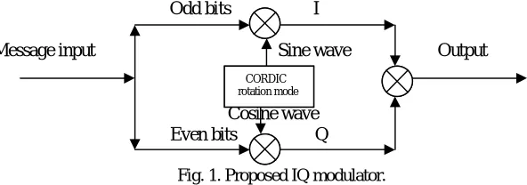
Figure.1. shows the proposed CORDIC based IQ modulator, it avoid large sized LUT consisting of amplitude samples of a sine wave. Upon recalling these values with an offset which calls these samples from its memory locations, generate a sine wave of a desired frequency. Offset determine the frequency of the sine wave in LUT based carrier generation. These wave is then used for the generation of its orthogonal wave. Resolution of wave generated by this system of signal generation depends upon number of bits of the LUT values, but when its modification required the whole LUT must be replaced which is a tedious work. In the CORDIC based carrier generation simple shift-add operation is required, no multiplication is required so it is simple and hardware efficient. It will produce sine and cosine waves at a time with same frequency so very useful for IQ carrier generation. Signal resolution in CORDIC based approach can be achieved by simple change in the code.
rectangular to polar convertor. CORDIC replace LUT based carrier generation as well as rectangular to polar conversion [2].
Odd bits I
Message input Sine wave Output
Cosine wave Even bits Q
Fig. 1. Proposed IQ modulator.
CORDIC based digital polar modulator is highly hardware , power efficient along with compact sized and faster in rectangular to polar conversion. It use nonlinear power amplifier in its final amplification stage which will give high power efficiency and increased battery life. It is best for multimode operation and it can accommodate both constant as well as non-constant envelop signals [3,4].
Odd bits
AM BIAS Sine wave
Message input I A
Q PM Even bits Cosine wave Q
Fig. 2. Proposed Polar transmitter.
II . CORDIC ALGORITHM
CORDIC refers to Coordinate Rotation Digital Computer, it is an efficient and simple hardware algorithm which use only addition, subtraction, binary shift and table lookup operation and is used to calculate hyperbolic and trigonometric functions. Here Volder’s algorithm is used for the implementation of various trigonometric functions. It is derived from the equations of a vector rotation [5,6].
x’= x cos(φ) – y sin(φ) (1) y’= y cos(φ) + x sin(φ) (2)
By rearranging these coordinate rotation equations for the hardware implementation result in a successful implementation of the hardware efficient CORDIC algorithm. By taking angle φ as the sum of some small angles, chosen such that their
tangents are all inverse power of two, we can easily implement these equations by using adder, subtractor, binary shifter and a small LUT containing above mentioned angle list. Number of angles in the table determines the number of rotations and signals accuracy and purity. On rearranging these equations changes to,
xi+1 = cos(φ)[x-y tan(φ)] (3)
yi+1 = cos(φ)[y+x tan(φ)] (4)
and then changes to,
X i+1= xi - yi. di. 2-I (5) CORDIC
rotation mode
CORDIC rotation mode
CORDIC vectoring mode
Y i+1= yi + xi. di. 2-I (6)
Z i+1= Zi- di. arctan(2-i), (7)
where di = -1, if Zi < 0,
= +1, otherwise.
Where value of di is determined by the direction of rotation of angle. The series of iterative rotations results in the
expected angle value, every rotation gives new x, y, z which were determine new x, y, z values. .
TABLE 1. ARCTAN TABLE
Step arctan Angle(degree) 10-bit binary
1 arctan(20) 45.0000 7F= 00 0111 1111
2 arctan(2-1) 26.5651 4B= 00 0100 1011
3 arctan(2-2) 14.0362 27= 00 0010 0111
4 arctan(2-3) 7.1250 14= 00 0001 0100
5 arctan(2-4) 3.5763 A= 00 0000 1010
6 arctan(2-5) 1.7899 5= 00 0000 0101
7 arctan(2-6) 0.8952 2= 00 0000 0010
8 arctan(2-7) 0.4476 1= 00 0000 0001
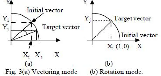
III. CORDIC MODES
The CORDIC algorithm operates in two modes, they are rotation mode and vectoring mode. In rotation mode, it is used for the generation of sine and cosine of an angle and in vectoring mode, it is used for rectangular to polar conversion. Rotation mode gives sine and cosine of an angle, by using a loop for incrementing angle we can achieve sine and cosine wave. It is achieved by implementing the hardware containing simple adder, subtractor, binary shifter and a small ROM table containing arctan angles [7]. This rotation operation is achieved by the implementation of equations 5, 6, 7. Rotation starts from x-axis and it iteratively rotates for each angle stored in the ROM table, for each angle corresponding x, y, z values are generated and which will become the input x, y and z of next rotation. Cosine and sine value are represented by final Xi+1 and
Yi+1. Zi+1 represent given input angle value, which will be achieved by all iterative rotations of the ROM table angles. For
In vectoring mode of CORDIC, there is also three inputs and two outputs. One of the important application of vectoring mode is rectangular to polar conversion, it is the main block of polar modulator. The two inputs x, y of CORDIC corresponds to rectangular coordinates and the z input corresponds to angle value which is set as zero for rectangular to polar conversion. In this mode driving y to zero, corresponding x and z gives magnitude and angle of polar value. Equation 5, 6, 7 is used for vectoring mode also by changing the conditions of direction of rotation as below ,
di = +1, if yi < 0
= -1, otherwise.
[Xj, Yj, Zj] = [1/K√(Xi2+Yi2), 0, arctan(Yi/Xi)]
In this work, we utilize both of these modes effectively for the implementation of polar modulator, this gives the advantages of fast rectangular to polar conversion and simultaneous production of carriers having same frequency with less hardware utilization. There is a tradeoff between numerical accuracy and implementation costs [8]. Input variables word length and number of iterations determine the accuracy of CORDIC processor. Optimal number of iterations will determine the speed, accuracy and hardware cost of the CORDIC.
IVIQ MODULATOR
It is the digital modulator system most commonly used in wireless devices today. In communication systems, information is communicated by means of a bandpass signal, which results from modulating a sinusoidal carrier. In continuous-time case any bandpass signal, s(t) with carrier frequency ωc , can be represented by the complex signal sc(t).
i.e., s (t) = Re |sc(t) e jωct |,
it can be rewritten as, s(t) = |sc(t)| cos( ωct +θ(t))
= I(t) cos ωct – Q(t) sinωct
Where I(t) is the in-phase component and Q(t) is the quadrature-phase component [1].
It is a QPSK modulator, in which input data is demultiplexed into two channels named I channel and Q channel. This I and Q path contains odd bits and even bits of the input data. Both I and Q bits are then multiplied with sine wave and cosine wave generated by the lookup table method. After this modulation generated I data and Q data are summed to get IQ modulated output. In this work lookup table method is replaced by CORDIC carrier generator. This will reduce the hardware utilization very much, by replacing large lookup table containing sine sample values by CORDIC arctan values. Figure.1 shows corresponding IQ modulator block diagram. Here rotation mode of CORDIC is utilized for the carrier generation with input values for x = 1, y = 0 and z = angle which determine the frequency of the carrier. Output values of x gives cosine wave and y gives sine wave.
V POLAR MODULATOR
Figure. 2 shows the proposed polar modulator system, which can be called as double CORDIC based polar modulator. Polar modulator is a modern digital modulation scheme which is very power efficient and compact in size. It use nonlinear power amplifiers for its output power amplification, thereby, use very less power compared with linear power amplifiers. So it will be more effective and efficient in new generation mobile handset with multiband and multimode capabilities.
the dc power of the amplifier. Thus phase modulated signal is amplified and change in bias by the magnitude gives amplitude amplification. This is how amplitude and phase modulation is achieved in a polar modulator.
|Sc(t)| = √(I2(t) + Q2(t))
Θ(t) = tan-1(I(t)/Q(t))
Polar modulator has several advantage over IQ based modulator [11]. Use of surface acoustic filters in multiband multimode IQ based transmitters to avoid unwanted spurious product due to baseband mixing is also avoided in polar modulators. This reduces the size of the devices very much. Conventional transmitters use class-A amplifiers or pre distortion techniques to avoid distortion of nonconstant envelopes and for linearization. Both of these methods require more power so battery life decreases. In polar modulator RF path contains only constant envelop signal, this way linearity is achieved simply. Polar modulator provide the advantages of less battery power consumption, smaller size, lower weight, high linearity, high efficiency and this technique work exceptionally well with the idea of integration.
VI.RESULTS AND DISCUSSIONS
Figure.4 shows the output of a LUT based carrier generation.
Fig.4. LUT based Sine and Cos wave generator.
It needs a large table of sine sample values and is stored in memory locations. We will call these by an offset value corresponding memory location. This offset determine the frequency of the carrier. This method generate only one type of wave at a time, for e.g. if it generate sine wave then cosine wave can be generated from this sine wave. This method is replaced by CORDIC method in this work. This is done in VHDL platform using ModelSim-Altera 6.6d.
0 5 10 15 0.4
0.5 0.6 0.7 0.8 0.9 1
Convergence to Sine and Cosine Calculation
No:of rotations
M
a
g
n
it
u
d
e
Cosine Converging CORDIC Cosine True Value Sine Converging CORDIC Sine True Value
Fig.5. CORDIC convergence to Sine and Cosine of an angle.
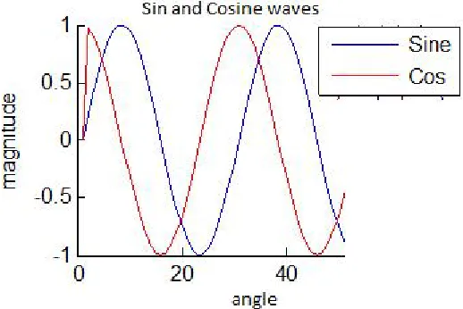
Figure. 6 shows the sine and cosine wave generated by CORDIC. It is obtained by looping and quadrant mapping of convergence values of angles. This method reduces the hardware utilization.
Fig.6.Output of a Sine and Cos wave generator.
0 50 100 -1
0 1
cosine
0 50 100
-1 0 1
sine
0 50 100
0 0.5 1
bit stream
0 50 100
0 0.5 1
I data
0 50 100
0 0.5 1
Q data
0 50 100
-1 0 1
I
0 50 100
-1 0 1
Q
0 50 100
-2 0 2
QPSK output
Fig.7. Matlab simulation result of IQ modulator.
Fig.8. Output of aCORDIC based IQ modulator.
TABLE II
LUT Vs CORDIC SIGNAL GENERATORS
Method No. of slices No. of LUTs No. Of registers
LUT 165 226 245
CORDIC 135 194 175
TABLE III
DEVICE UTILIZATION OF CORDIC BASED POLAR MODULATOR*
Number of Slice Registers: 2201 Out of 408,000 1%
Number of Slice LUTs: 2157 out of 204,000 1%
Number used as Memory: 29 out of 70,200 1%
VII.CONCLUSION
IQ modulator and polar modulator are the two modulators used in mobile communication devices. Polar modulator is a newly developed modulation technique, which will become the important part of future mobile communication systems, as it is compact, linear, highly efficient and gives more battery life. Simulation results shows that application of CORDIC techniques in both the modulators are successful, efficient and compact. Here advantages of CORDIC is utilized in the polar modulator system with very less hardware. Future generation mobile systems can also support this technique but require more research for its optimum hardware implementation.
REFERENCES
[1]. In-Seok Jung, Yong-Bin Kim, “ A CMOS Low-Power Digital Polar Modulator System Integration for WCDMA Transmitter,” IEEE. transactions on Industrial Electronics, vol.59, no.2, February 2012.
[2]. D. D. Hwang, D. Fu, and A. N. Willson, Jr., “A 400-MHz processor for the conversion of rectangular to polar coordinates in 0.25-μm CMOS,” IEEE J. Solid-State Circuits, vol. 38, no. 10, pp. 1771–1775, Oct. 2003.
[3]. E.W. McCune, “Multi-mode and multi-band polar transmitter for GSM, NADC, and EDGE,” in Proc. WCNC, Mar. 2003, pp.812-815.
[4]. D. Rudolph, “Out-of-band emissions of digital transmissions using Kahn EER technique,” IEEE Trans. Microw. Theory Tech., vol. 50, no. 8, pp. 1979- 1983, Aug. 2002.
[5]. J. E. Volder, “ The CORDIC trigonometric computing technique,” IRE Transactions on Electronic Computers, vol.8, no.3, pp. 330-334, 1959. [6]. R. Andraka, “ A survey of CORDIC algorithms for FPGA based computers,” in Proceedings of the 6th ACM/SIGDA International Symposium on Field Programmable Gate Arrays (FPGA’98), pp. 191-200, February 1998.
[7]. T. Menakadevi, M. Madheswaran, “ Direct Digital Synthesizer using Pipelined CORDIC Algorithm for Software Defined Radio,” International Journal of Science and Technology, vol. 2, no. 6, June 2012.
[8]. K. Kota and J. Cavallaro, “ Numerical accuracy and hardware tradeoffs for CORDIC arithmetic for special- purpose processors,” IEEE Trans. Comput. , vol.42, no. 7, pp. 769-779, Jul. 1993.
[9]. Tandur and M.Moonen, “Joint adaptive compensation of transmitter and receiver IQ imbalance under carrier frequency offset in OFDM- based systems,” IEEE Trans. Signal Process., vol. 55, no. 11, pp. 5246-5252, Nov. 2007.
[10]. C. Chen, H. Ko, Y.Wang, H. Tsao, K. Jheng, and A.Wu, “Polar transmitter for wireless communication system,” in Proc. ISPACS, Dec. 13-16, 2005, pp. 613-616.