Optimum Viterbi Decoder Design and its
Implementation on FPGA
Shankari N.1, Shrividya G.2
M. Tech Student, Department of ECE, NMAMIT, Nitte, Udupi district, Karnataka, India 1
Associate Professor, Department of ECE, NMAMIT, Nitte, Udupi district, Karnataka, India 2
ABSTRACT:The Viterbi decoder is the most important part in the receiver. Viterbi algorithm is one of the most common decoding algorithms used for decoding convolutional codes. Viterbi decoder employs Maximum Likelihood (ML) technique to decode the convolutionally encoded data stream. Viterbi decoding algorithm is an attractive solution to many digital estimation problems. With the growing use of digital communication, there has been an increased interest in high speed Viterbi decoder design within a single chip. Advanced Field Programmable Gate Array (FPGA) technologies and well developed Electronic Design Automatic (EDA) tools have made it possible to realize a Viterbi decoder with the throughput at the order of Giga-bit per second, without using off-chip processors or memory. In practice, most of the communication systems use Viterbi decoding scheme in processors. This paper involves designing an optimum structure of Viterbi decoder and implementation on Field Programmable Gate Array (FPGA), which in turn base for Intellectual Property (IP) development.
KEYWORDS: Viterbi decoder, Maximum Likelihood (ML), Signal to Noise Ratio(SNR), Error Detection and Correction(EDC), Branch metric, Path metric, Trace-back, Hamming distance, survivor path
I. INTRODUCTION
In wireless communication systems noise and interference level in the channel is very high. It greatly affects the Signal to Noise Ratio (SNR). Hence certain Error Detection and Correction (EDC) techniques are required to improve SNR.An error correcting code which is used in most of the communication systems is convolutional code. Most of the transmitters use convolutional encoder to add redundancy to the information being transmitted. Hence the effective technique to decode the convolutionally encoded data is Viterbi decoder.Viterbi decoder uses Viterbi algorithm to decode the data. It involves Maximum Likelihood (ML) decoding where the computational load is reduced. The algorithm will use Trellis structure [1].There are 2 types of Viterbi decoder implementation namely hard decision Viterbi decoding and soft decision Viterbi decoding. The implementation of hard decision Viterbi decoder involves finding Hamming distance metric and the path with lowest Hamming distance metric (cumulative metric) is called survivor path. The number of bit positions by which the received symbol and actual symbol differ is Hamming distance [5]. If Hamming distance is zero, indicate that the symbol or data is received as it is transmitted without any error. The implementation of soft decision Viterbi decoder involves finding metric used is Euclidean distance. This is squared difference between received symbol and actual symbol. In this type the received symbol is quantized into more than two levels and Euclidean distance is calculated [5]. The path with minimum Euclidean distance is considered as survivor path. Soft decision decoding will be better compared to hard decision because soft decision decoding will have more information about the received information compared to hard decision decoding.
II. RELATEDWORK
of convolutional encoded code. The decoding will start at '0' state by the assumption that encoding will start from the same state. Actually the ML decoding will be independent of initial states [4].The ML decoding involves selection of low metric path as winning path. The winning path will have low bit error path compared to other paths. The metric is Hamming distance metric in hard decision Viterbi decoder and Euclidean distance metric in soft decision Viterbi decoder. Parallel implementation of Viterbi decoder is possible [7].
III.CONVOLUTIONAL ENCODER
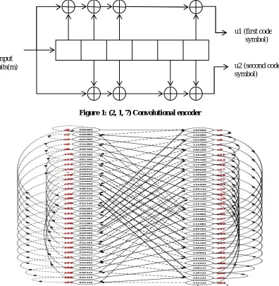
A (2, 1, 7) convolutional encoder which is base for Viterbi decoder design is as shown in Figure 1. The output from
Convolutional encoder mainly depend on generator vectors (171)oand (133)o. It also has constraint length 7 and code
rate ½.
Figure 1: (2, 1, 7) Convolutional encoder
Figure 2: State diagram of (2, 1, 7) Convolutional encoder
Input bits(m)
u1 (first code symbol)
Since there are 6 shift registers in designed encoder structure, state diagram involves 26= 64 states. The all possible state transitions are graphically represented in Figure 2. The state transition mainly depends on input bit (‘0’ or ‘1’). Based on input arrived into Convolutional encoder there will be two transitions from each state. Hence 64 states will have 128 transitions. The rate of the Convolutional encoder mainly depends on number of bits inputted and number of output bits obtained. For each input bit enter into Convolutional encoder shown in Figure 1, two bit outputs are obtained. This is due to the rate of Convolutional encoder which is ½. The reliability of transmission in a communication system is improved by encoding at transmitter.
IV.VITERBI DECODER
Figure 3: Block diagram of Viterbi decoder [4]
The general block diagram of Viterbi decoder is as shown in Figure 3. The main blocks are Branch Metric Unit (BMU), Add-Compare-Select Unit (ACSU), Path Metric Unit (PMU) and Trace-Back Unit (TBU). The base for Viterbi decoder design is Trellis structure of proposed Convolutional encoder. Hence there will be 64 states for Viterbi decoder design. For every new input symbol arrived each state will go into two other new states. There are pre-obtained codewords for each state transition. Viterbi decoder finds hamming distance between input codewords and pre-obtained codewords of each transition. When new symbol arrives into Viterbi decoder the hamming distance accumulates and leads into path metric. Viterbi decoder selects a state with minimum path metric as surviving state. Path along with this stateis called survivor path. The decision bits along the survivor path are taken as actual decoded output.
Branch Metric Unit (BMU)
This unit calculates Hamming distance metric in hard decision decoding and Euclidean distance in soft decision decoding. In hard decision Viterbi decoding it involves Exor-ing of received symbol as well as actual code symbol and counting the number of 1's to identify Hamming Distance (HD) as shown in Figure 4. In the case of soft decision Viterbi decoding the free distance formula is used to find squared distance between received codewords and actual code word. For hard decision Viterbi decoderthe number of clock cycles consumed by branch metric unit is equal to number of symbols.Let 'N' be the number of code symbols applied to Viterbi decoder to decode. Then branch metric value is calculated in 'N' clock cycles.
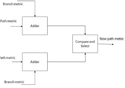
Add-Compare-Select Unit (ACSU)
high, the new path metrics and state values are calculated as well as the state bit values are stored in different array before new symbol is arrived. This is because the state bit values are required for trace-back to obtain final decoded output. But the obtained path metric value is input to next iteration and updated.For one symbol, the new path metric for all state transition are calculated in first clock cycle. Since each state will have two path metric values, the one with minimum value is taken along with state information and stored in next two clock cycles. Hence one symbol takes three clock cycles andhence for 'N' symbols, 3N clock cycles are required to complete the add-compare-select operation.
Figure 4: Branch Metric Unit (BMU) Path Metric Unit (PMU)
This computes path metric for each state from initial state as the new symbol arrives in each time. The path metric for each state is stored and added to the branch metric of new received symbol. The Add-Compare-Select and path metric computation is continued till it reaches to decoding depth/back depth. Once the back depth is reached back is started at the same time. Add-Compare-Select and path metric computation is performed in parallel with trace-back.
Trace-Back Unit (TBU)
Once the trace-back length/decoding depth is reached the decision bits are traced back along the winning path/survivor path to identify the decoded bits. The state which has minimum cumulative path metric is selected as winning state and the path along that to initial stage is winning path. The decision bits along that winning path give actual decoded sequence. For better performance trace-back length was chosen as greater than or equal to 5 times constraint length. The trace-back operation requires one clock cycle to enable trace-back, two clock cycles for finding minimum value of path metric from the array and N cycles to obtain N decoded bits. Hence the total trace-back requires N + 3 clock cycles for N symbols.
Figure 5: Add-Compare-Select Unit (ACSU)
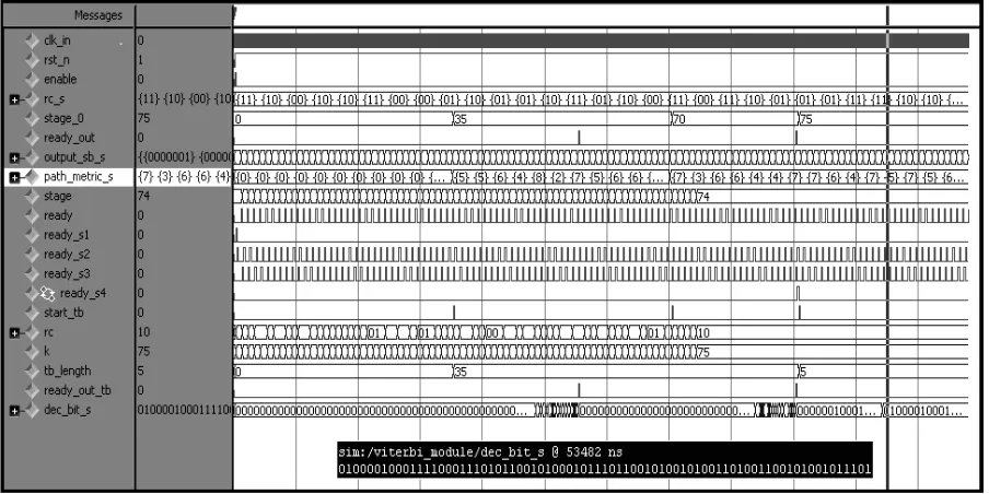
V. SIMULATION RESULT
VHDL code for optimum design of Viterbi decoder is simulated using Modelsim 6.5b and synthesized using Xilinx 12.2. The simulation result is as shown in Figure 6. 75 symbols are fed as input into Viterbi decoder. Trace-back length chosen was 36. The resource utilization details of designed Viterbi decoder obtained after synthesis. Table 1 shows the resource utilization for designed Viterbi decoder on FPGA (Spartan 6,xc6slx150t,-3).
Figure 6: Simulation result of Viterbi decoder Table:1 Resource utilization table of Viterbi decoder
Resources Utilization Percentage utilization
Number of Slice Registers: 6902 out of 184304 3%
Number of Slice LUTs: 5796 out of 92152 6%
Number of fully used LUT-FF pairs 1553 out of 11145 13%
Number of unique control sets 94
Number of bonded IOBs 6 out of 396 1%
Adders/Subtractors 135
Counters 3
Registers 36042
Comparators 65
Multiplexers 810
1 bit EX-ORs 8
VI.CONCLUSION
with code rate ½ and constraint length 7 which require 64 states, 4 parallel Branch Metric Units (BMUs) and 32 parallel Add-Compare-Select Units (ACSUs). The two ACSUs are combined in one module.The optimization in designed structure is required to obtain better design with low resource requirement, low power and high speed. The VHDL codes are generated in different code modules for each blocks of Viterbi decoder and then integrated. The designed Viterbi decoder is able to correct single as well as two bits errors. In general it corrects random errors. It is observed that number of resources required implementing Viterbi decoder on FPGA (Spartan 6, xc6slx150t,-3), by optimizing VHDL code are minimum compared to conventional Viterbi structure.
REFERENCES
[1] A.J. Viterbi, “Error Bounds for Convolutional Codes and Asymptotically Optimum Decoding Algorithm”, Institute of Electrical and Electronics Engineers Transactions on Information Theory, IT-13, pp. 260-269, 1967.
[2] Bernard Sklar, “Digital Communications-Fundamentals and Applications-Second Edition”, Prentice Hall P T R, New Jersey, pp. 381-435. [3] G. D. Forney Jr, “The Viterbi algorithm”, Proceedingson Institute of Electrical and Electronics Engineers, pp. 268-278, 1973.
[4] Yan Sun and Zhizhong Ding, “FPGA Design and Implementation of Convolutional Encoder and a Viterbi Decoder Based on 802.11a for OFDM”, Department of Communication Engineering, Hefei University of Technology, pp. 125-131,2012.
[5] Hui-Ling Lou, “Implementation of the Viterbi Algorithm”, Institute of Electrical and Electronic EngineersAcoustics, Speech, and Signal Processing Magazine, pp. 26-41, 1995.
[6] Matthias Kamuf, Viktor Owall, and John B. Anderson, “Optimization and Implementation of Viterbi Decoder under Flexibility Constraints” Institute of Electrical and Electronics Engineers Transactions on Circuits and Systems regular papers, pp. 2411-2422, 2008
[7] Gerhard Fettweis and Heinrich Meyr, “High-Speed Parallel Viterbi Decoding: Algorithm and VLSI-Architecture”,Institute of Electrical and ElectronicsEngineers Communications Magazine, pp. 46-55, 1991.
![Figure 3: Block diagram of Viterbi decoder [4]](https://thumb-us.123doks.com/thumbv2/123dok_us/1518382.1186055/3.595.133.460.320.465/figure-block-diagram-viterbi-decoder.webp)