Dept. of EEE, College of Engineering, Trikaripur (CAPE, Government of Kerala), Cheemeni, Kasaragod, Kerala-671313, India
Independent Control of Speed and Torque in a
Vector Controlled Induction Motor Drive
using Predictive Current Controller and
SVPWM
Vandana Peethambaran
1,Dr.R.Sankaran
2Assistant Professor, Dept. of EEE, College of Engineering Trikaripur, Kerala, India.1
Professor, Dept. of EEE, SASTRA University, Thanjavur, Tamil Nadu, India.2
ABSTRACT:This paper deals with the theory and simulation of a closed loop vector controlled induction motor drive
system using predictive current controller theory and space vector PWM. For improving the overall performance of the drive system the vector controlled strategy is adopted so as to decouple the stator current components for producing rotor flux and shaft torque. The various analytical equations governing the motor and the associated control and calculation blocks are derived in a connected manner and implemented using SIMULINK. Typical problems encountered in a high-performance drive are formulated and a set of performance characteristics of the system are obtained by repeated runs of the schematic model. These results indicate effective interaction between the power and control circuits leading to highly desirable features like variable frequency, variable voltage operation and
field-orientation with independent control of air gap flux and torque of the motor.
KEYWORDS: Induction motor drive, predictive current controller, field oriented control, space vector PWM.
I. INTRODUCTION
Extensive research on the development of variable speed drives (VSD) using the industry-standard 3-phase cage induction motor have been reported during the last 3 decades. This important area has passed through significant milestones characterised by the following schemes: Fixed frequency variable voltage control suitable for fan or blower type loads; Constant V/F (scalar) control and the Field oriented (vector) control for variety of applications. The advent of Field Oriented control (FOC) invented by Blaschke [1] is a major breakthrough in the area variable speed control of induction motors.It is based upon decoupling of the two components of the stator current, one producing airgap flux and the other producing electromagnetic torque. The scheme requires a 3-phase supply from a PWM inverter, where the voltage, frequency and individual phase angle of the outputs can be controlled. It provides independent control of torque and flux during both dynamic and steady state conditions. One important feature of the field orientation is the knowledge of field angle [2] Krishnan, which is either measured or estimated. Accordingly, FOC is classified into two types: Direct Field Oriented control (DFOC) and Indirect Field Oriented control (IFOC). In view of the cost and accuracy considerations in the measurement of field angle, IFOC has emerged as a very popular scheme for most industrial applications. Here, the rotor flux vector estimation and space orientation are carried out using the machine model and its parameters and the field angle is calculated by feed forward of the slip variable. Similarly, several studies and research have been done to find an appropriate technique for the predictive stator current control of induction motor drives.
In this paper, the full theoretical equations covering the IM model in α-β and d-q frame of references, IFOC
Fig.1.IM VSD with IFOC and PCC.
The full SIMULINK schematic containing a number of subsystems along with various parameters and operational data is created for simulating typical problems in a cage induction motor drive system. These are the classical start up transient run under load; Stable run at multiple speed-torque combinations. The performance of the controller and the overall system are investigated by repeated runs of the schematic and a set of simulation results are presented.
II. INDUCTION MOTOR MODEL
The model of a 3-phase VSI fed cage induction motor covering voltage, current, flux, speed and torque variables in (d-q) axis frame is well-known and is widely used in the literature [2] [5] [6] This model is characterised by sinusoidal flux density distribution in the airgap and no saturation of the magnetic field. This model is well suited for solving various problems related to variable frequency, voltage or current and also speed and torque disturbances etc., during the operation of the machine. The motor can be modelled either in stationary, rotor or synchronously rotating reference frames [2], [5] and the former is used in this paper.
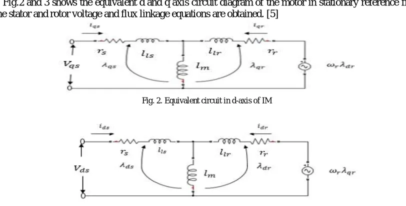
Fig.2 and 3 shows the equivalent d and q axis circuit diagram of the motor in stationary reference frame from
which the stator and rotor voltage and flux linkage equations are obtained. [5]
Fig. 2. Equivalent circuit in d-axis of IM
Fig. 3. Equivalent circuit in q-axis of IM
The stator and rotor voltage equations in d-q axes are:
= + (1)
Dept. of EEE, College of Engineering, Trikaripur (CAPE, Government of Kerala), Cheemeni, Kasaragod, Kerala-671313, India
0 = − + (3)
0 = + + (4)
Where = = 0 as the rotor is short circuited and , , , are the rotor and stator flux linkages in d and q axis respectively As indicated in Fig. 2 and 3 the stator and rotor flux linkage equations are [2] = + (5)
= + (6)
= + (7)
= + (8)
where = + is the stator inductance and + is the rotor inductance The electromagnetic torque developed is given by [2] [5] = ( − ) (9)
The torque balance equation while driving a load of torque TL is given by = + + (10)
where is the mechanical angular velocity. The rotor angular velocity in electrical radians per second is obtained as = (11)
Substituting (11) in (10) we get
=
+
+
(12)
where , and represent the number of poles, moment of inertia and viscous friction of the drive system respectively. III. FIELD ORIENTED CONTROL FOC is analogous to the energy conversion process in a DC machine, where field flux is always in quadrature with armature flux, enabiling independent variation flux and torque.[5] .In this paper, Indirect method of FOC is used alongwith the observer discussed above. Further, to generate a reference torque signal ∗, a speed controller is introduced where the actual speed from the induction motor is compared with the desired speed reference setting to generate the speed error signal and processed through a PI controller. The following set of equations cover the mechanism of generating the above ∗, satisfying the principles of field orientation. The rotor circuit equations can be written as Solving and from eqns. (5)-(8), ∗ = − (13)
∗ = − (14)
Substituting eqns. (13) and (14) in (3) and (4), we get + − −( − ) = 0 (15)
+ − + ( − ) = 0 (16)
For decupled control, the necessary conditions are [6] =0, =0 and = (17)
Hence the governing equation for slip speed under FOC is obtained as [6] = (18)
which is used for estimating the shaft speed. By transforming the above stator current variables into αβ frame, the
reference data for the PCC is obtained and used below.
In this paper, PCC is implemented by computing the voltage required to reach the desired current at the end of next sampling period. The idea is to calculate the desired voltage space vector at the current sampling instant for
realising the transformed desired value of the stator current components ∗ and ∗ as indicated below
( ) ( )
= ( ) ( ) (19)
Hence ( ) = [ ( ) ( ) ] + ( ) (20)
where + 1is the next sampling instant and Tsmp is the sampling interval.
Based upon the calculation of voltage space vector covering both magnitude and sector angle the parameters
of PWM waveform for a switching frequency fs are determined as presented in [7] [8] [9 ]
V. SIMULATION SCHEMATIC
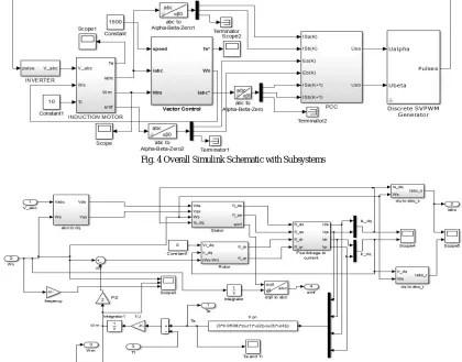
The simulation schematic covers the full power control and feedback circuits in the form of an overall block
diagram is given in Fig. 4
It contains the following subsystems
i) Induction motor model
ii) Field oriented control model
iii) Predictive Current Controller block
iv) Space Vector PWM module
The details of the above subsystem blocks are presented separately as Figs. 5, 6 and7
Fig. 4 Overall Simulink Schematic with Subsystems
Dept. of EEE, College of Engineering, Trikaripur (CAPE, Government of Kerala), Cheemeni, Kasaragod, Kerala-671313, India
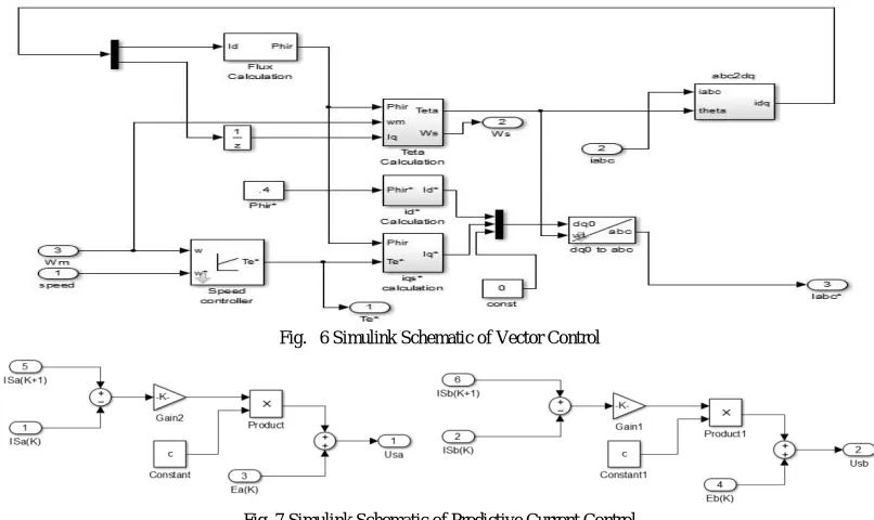
Fig. 6 Simulink Schematic of Vector Control
Fig. 7 Simulink Schematic of Predictive Current Control
These subsystems, where the individual input and output variables are indicated, implement the corresponding equations presented in the previous sections and together make up the full schematic.
VI. SIMULATION RESULTS
The simulation results are grouped into 2 typical problems as follows:
A) Start up transient under load with specified speed setting and load torque = 10 N-m. A.1: Variation of speed when the given reference speed = 1500rpm
A.2: Variation of speed when the given reference speed = 1000rpm A.3: Variation of speed when the given reference speed = 600rpm B) Stable run at multiple speed-torque combinations.
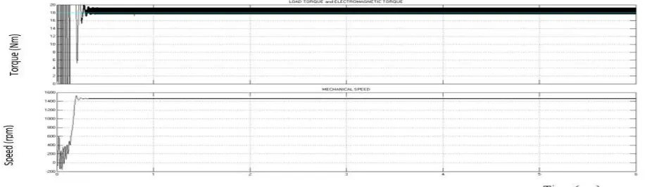
B.1: Variation of speed and electromagnetic torque when the load torque = 2Nm and reference speed = 600rpm. B.2: Variation of speed and electromagnetic torque when the load torque = 2Nm and reference speed = 1500rpm. B.3: Variation of speed and electromagnetic torque when the load torque = 18Nm and reference speed = 600rpm.
B.4: Variation of speed and electromagnetic torque when the load torque = 18Nm and reference speed =
1500rpm.
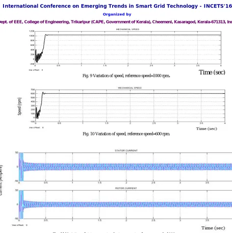
Fig.8, 9 and 10 gives the results of the problem (A) for the speed settings of 1500 rpm,1000 rpm and 600 rpm covering a speed ratio of 2.5 : 1
Fig. 9 Variation of speed, reference speed=1000 rpm
.
Fig. 10 Variation of speed, reference speed=600 rpm.
Fig. 11 Variation of stator currentand rotor current, reference speed =1000rpm
Fig. 11 and 12 show the variation of stator and rotor currents and the electromagnetic torque during the start up for a
typical reference speed of 1000rpm and TL = 10 N-m
Fig. 12 Variation of Electromagnetic torque during start up (Tl=10N-m)
Fig. 13 14 and 15 shows the variation of speed and torque when the reference speed and load torque are 600rpm and 2Nm, 1500rpm and 2Nm, 600rpm and 18Nm,1500rpm and 18Nm respectively.
Dept. of EEE, College of Engineering, Trikaripur (CAPE, Government of Kerala), Cheemeni, Kasaragod, Kerala-671313, India
Fig. 14 Variation of torque and speed for reference speed = 1500rpm and Load torque = 2Nm
Fig. 15 Variation of torque and speed for reference speed = 600rpm and Load torque = 18Nm
VIII. CONCLUSION
By Integrating multiple functional blocks in the form of subsystems, an elaborate SIMULINK schematic of a vector controlled induction motor drive system that is capable of simulating typical problems connected with a high performance digital controlled drive has been developed, The simulation results validate the assumptions and equations used for modelling the related electromagnetic and electromechanical phenomena and the control algorithm and also reveal the significant features of the closed loop drive system. The attainment and retention of field orientation and realization of independent control of airgap flux and shaft torque through predictive control of the stator currents are important results of the investigation. It is found that the drive system is capable of quickly responding to required changes in speed and torque on the load side, and the controller is versatile for fast variation of inverter frequency and voltage.
MACHINE AND CONTROL PARAMETERS:
The motor is rated at 5.5KW, 220V, 50Hz and 1440rpm. The motor parameters are rs= 0.183Ω,
rr= 0.277Ω, ls = 0.0553H, lr = 0.056H
lm = 0.0538H, P = 4, J = 0.0165Kg-m,
B = 0.000086 N-m/rad/sec.
Kob= 0.25 , Kp = 0.25, Ki = 0.025
REFERENCES
[1] F. Blaschke, “The principle of field orientation as applied to the new transvector closed loop system for rotating field machines,” Siemens Review, vol. 34, pp. 217-220, May 1972.
[2] R. Krishnan, “Electrical Motor Drives Modelling, Analysis and Control,” Prentice Hall, 2006.
[3] J. Holtz, “Sensorless Control of Induction Motor Drives,” Proceedings of the IEEE, vol. 90, No. 8, Aug. 2002, pp. 1359-1394.
[4] H. Abu-Rub and J. Guzinski, “Simple observer for induction motor speed sensorless control,” in Proc. 37th Annu. Conf. IEEE Ind. Electron. Soc.
IECON, Melbourne, Australia, Nov. 7-10, 2011, pp. 2024-2029.
[5] B. K.Bose, “Modern Power Electronics and AC Drives,” Prentice Hall, 2002. [6] P. C. Krause, “Analysis of Electrical Machinery,” McGraw-Hill Book Company, 1986.
[7] S. K. Pillai, “Analysis of thyristor power-conditioned motors,” University Press, Hyderabad, 1992.
[8] A. Lekshmi, Dr. R. Sankaran, Dr. S. Ushakumari, “Modelling and simulation of permanent magnet brushless dc motor based spooler drive system with speed and current feedback,” International Review on Modelling and Simulation, vol. 5, no1, pp. 231-238, Feb. 2012.
[9] Vandana Peethambaran, Dr. R. Sankaran, “Modelling and Simulation of Sensorless Vector Controlled Induction Motor Drive System using Observer Theory and Predictive Current Control,” International Journal of Advanced Information Science and Technology, vol.33, No.33, January 2015.
BIOGRAPHY
Vandana Peethambaran was born in Kannur, Kerala, India on 5thOctober 1989. She took her
B.Tech degree in Electrical and Electronics Engineering in 2011 and pursued M.Tech degree in Power Electronics and Drives from SASTRA University, Thanjavur, Tamil Nadu and is currently working as Assistant Professor at College of Engineering Trikaripur, Kerala She has published research papers in International Journal of Advanced information Science and Technology Her interest include Drives and their Control.
Dr. R. Sankaran was born in Trivandrum, India on 28th September 1943. He obtained his B.Tech