University of Windsor University of Windsor
Scholarship at UWindsor
Scholarship at UWindsor
Electronic Theses and Dissertations Theses, Dissertations, and Major Papers
2009
Ferritic nitrocarburizing process development for minimization of
Ferritic nitrocarburizing process development for minimization of
distortion
distortion
Chunyan Nan
University of Windsor
Follow this and additional works at: https://scholar.uwindsor.ca/etd
Recommended Citation Recommended Citation
Nan, Chunyan, "Ferritic nitrocarburizing process development for minimization of distortion" (2009). Electronic Theses and Dissertations. 7918.
https://scholar.uwindsor.ca/etd/7918
Ferritic Nitrocarburizing Process Development
for Minimization of Distortion
by
Chunyan Nan
A Thesis
Submitted to the Faculty of Graduate Studies
through Materials Engineering
in Partial Fulfillment of the Requirements for
the Degree of Master of Applied Science at the
University of Windsor
Windsor, Ontario, Canada
1*1
Library and Archives CanadaPublished Heritage Branch
395 Wellington Street Ottawa ON K1A 0N4 Canada
Bibliotheque et Archives Canada
Direction du
Patrimoine de I'edition
395, rue Wellington OttawaONK1A0N4 Canada
Your file Vote reference ISBN: 978-0-494-57618-2 Our file Notre reference ISBN: 978-0-494-57618-2
NOTICE: AVIS:
The author has granted a
non-exclusive license allowing Library and Archives Canada to reproduce, publish, archive, preserve, conserve, communicate to the public by
telecommunication or on the Internet, loan, distribute and sell theses
worldwide, for commercial or non-commercial purposes, in microform, paper, electronic and/or any other formats.
L'auteur a accorde une licence non exclusive permettant a la Bibliotheque et Archives > Canada de reproduire, publier, archiver,
sauvegarder, conserver, transmettre au public par telecommunication ou par I'lnternet, prefer, distribuer et vendre des theses partout dans le monde, a des fins commerciales ou autres, sur support microforme, papier, electronique et/ou autres formats.
The author retains copyright ownership and moral rights in this thesis. Neither the thesis nor substantial extracts from it may be printed or otherwise reproduced without the author's permission.
L'auteur conserve la propriete du droit d'auteur et des droits moraux qui protege cette these. Ni la these ni des extraits substantiels de celle-ci ne doivent etre imprimes ou autrement
reproduits sans son autorisation.
In compliance with the Canadian Privacy Act some supporting forms may have been removed from this thesis.
While these forms may be included in the document page count, their removal does not represent any loss of content from the thesis.
Conformement a la loi canadienne sur la protection de la vie privee, quelques formulaires secondaires ont ete enleves de cette these.
Bien que ces formulaires aient inclus dans la pagination, il n'y aura aucun contenu manquant.
DECLARATION OF CO-AUTHORSHIP/PREVIOUS PUBLICATIONS
I hereby declare that this thesis incorporates material that is the result of a joint
research undertaken in collaboration with Dr. Xichen Sun from the Powertrain Materials
Engineering Department of Chrysler LLC under the supervision of professors Derek O.
Northwood and Randy J. Bowers. The research collaboration is covered in Chapters 4, 5,
and 6 of the thesis. In all cases, the key ideas, primary contributions, experimental
designs, data analysis and interpretation, were performed by the author, and the
contributions of the co-authors was in the capacity of supervision of the research in the
form of technical advice and suggestions.
I am aware of the University of Windsor Senate Policy on Authorship and I certify
that I have properly acknowledged the contributions of other researchers to my thesis, and
have obtained permission from each of the co-authors to include the above materials in
my thesis.
I certify that, with the above qualification, this thesis, and the research to which it
refers, is the product of my own work.
This thesis includes five original papers that have been previously
published/submitted for publication in peer reviewed journals, as follows:
1. C. Nan, D.O. Northwood, R.J. Bowers, X. Sun and P. Bauerle, Residual Stresses
and Dimensional Changes in Ferritic Nitrocarburized Navy C-rings and Prototype
Stamped Parts Made from SAE 1010 Steel, Proceedings of the SAE World
Congress & Exhibition, April 2009, Detroit, ML U.S.A., Paper No. 2009-01-0425,
SAE International, Warrendale, PA, U.S.A. Also accepted for publication in the
SAE International Journal of Materials & Manufacturing.
2. C. Nan, D.O. Northwood, R.J. Bowers and X. Sun, Distortion in Ferritic
Nitrocarburized SAE 1010 Plain Carbon Steel, Proceedings of the 2009 SEM
Annual Conference and Exposition on Experimental and Applied Mechanics, 1-3
June 2009, Albuquerque, New Mexico, U.S.A.
3. C. Nan, D.O. Northwood, R.J. Bowers, X. Sun and P. Bauerle, The use of Navy
Proceedings of the Surface Effects and Contact Mechanics IX, Computational
Methods and Experiments, WIT Transactions on Engineering Sciences, WIT
Press 2009, Vol. 62, pp. 13-25.
4. C. Nan, D.O. Northwood, R.J. Bowers and X. Sun, Study on the Dimensional
Changes and Residual Stresses in Carbonitrided and Ferritic Nitrocarburized SAE
1010 Plain Carbon Steel. Accepted for publication in the Proceedings of the
Thermec' 2009 International Conference, 25-29 August 2009, Technical
University-Berlin, Germany.
5. C. Nan, D.O. Northwood, R.J. Bowers and X. Sun, Nitrocarburizing of a SAE
1010 Steel Automotive Component. Submitted on 25 April 2009 for publication in
Materials Forum.
I certify that I have obtained permission from the copyright owners to include the
above published materials in my thesis. I certify that the above material describes work
completed during my registration as a graduate student at the University of Windsor.
I declare that, to the best my knowledge, my thesis does not infringe upon
anyone's copyright nor violate any proprietary rights and that any ideas, techniques,
quotations, or any other material from the work of other people included in my thesis,
published or otherwise, are fully acknowledged in accordance with the standard
referencing practices. Furthermore, to the extent that I have included copyrighted material
that surpasses the bounds of fair dealing within the meaning of the Canada Copyright Act,
I certify that I have obtained permission from the copyright owners to include such
materials in my thesis.
I declare that this is a true copy of my thesis, including any final revisions, as
approved by my thesis committee and the Graduate Studies office, and that this thesis has
ABSTRACT
Nitrocarburizing is a thermochemical diffusion process that has been proposed as
an alternative to carbonitriding to improve the surface characteristics of automotive
components without producing unacceptable part distortion. In this study, gas, ion and
vacuum ferritic nitrocarburizing using various heat treatment schedules were investigated
and compared with a current carbonitriding procedure. Dimensional distortion and
residual stresses in Navy C-Rings and torque converter pistons resulting from each
treatment process were evaluated. The microstructure and microhardness, as well as the
phase composition of the specimens, were also characterized.
The results of this study indicated that the nitrocarburizing process utilizing
suitable heat treatment procedures gave rise to smaller size and shape variations in
specimens than carbonitriding. However, given the tensile surface residual stresses
induced by nitrocarburizing, additional wear testing needs to be carried out to confirm the
possibility of replacing the current carbonitriding process with an appropriate ferritic
ACKNOWLEDGEMENTS
First and foremost, I would like to express my heartfelt appreciation to my
advisors Dr. Derek O. Northwood and Dr. Randy J. Bowers for their instructive
supervision, encouragement, and steadfast support during my graduate studies. It has
been a great pleasure working with them, and my academic experience here has been
both challenging and rewarding.
I also wish to extend my thanks to my committee members: Dr. J. Johrendt, Dr.
V. Stoilov, and Dr. D. Ting for their invaluable suggestions and time. The laboratory
assistance of Mr. J. Robinson is also much appreciated.
Special thanks are extended to Dr. Xichen Sun for providing technical suggestions
and coordinating the tests performed at the Chrysler Technology Center and the
commercial heat treaters throughout this project. The financial support of the Powertrain
Materials Engineering Department of Chrysler LLC and the University of Windsor are
TABLE OF CONTENTS
DECLARATION OF CO-AUTHORSHIP/PREVIOUS PUBLICATIONS Ill
ABSTRACT V
DEDICATION VI
ACKNOWLEDGEMENTS VII
LIST OF TABLES XI
LIST OF FIGURES XII
LIST OF ABBREVIATIONS XIX
I. INTRODUCTION 1
2.1 SURFACE HARDENING OF STEEL 4
2.1.1 Carburizing 4 2.1.2 Carbonitriding 5 2.1.3 Nitriding 8 2.1.4 Ferritic Nitrocarburizing 9
2.2 NAVY C-RINGS AND TORQUE CONVERTER PISTONS 14
2.2.7 Fabrication of Torque Converter Pistons 75
2.2.2 Pistons in Torque Converter 18
2.3 DISTORTION 20
2.3.1 Basic Distortion Mechanisms 20 2.3.2 Size and Shape Distortion 23 2.3.3 Distortion during Carbonitriding and Nitrocarburizing 23
2.3.4 Distortion Correction 24
2.4 RESIDUAL STRESSES 27
2.4.1 Origins of Residual Stresses 27 2.4.2 Residual Stresses in Surface Hardened Steels 30
2.4.3 Measurement of Residual Stresses Using X-Ray Diffraction 32
III. EXPERIMENTAL DETAILS 35
3.1 OVERVIEW 35
3.2 TEST SPECIMENS 36
5.2.7 Material and Texture 36
3.2.2 Geometry of Navy C-rings 38 3.2.3 Geometry of Torque Converter Piston 39
3.3 HEAT TREATMENT DETAILS 40
3.4 MET ALLOGRAPHS PROCEDURES 45
3.4.2 Scanning Electron Microscopy 46
3.5 Mi CROHARDNESS TESTING 47
3.6 PHASE ANALYSES 47
3.7 DIMENSIONAL MEASUREMENTS AND CALCULATION OF DISTORTION 48
3.7.1 CMMMeasurements of C-ring Specimens 49
3.7.2 CMM Measurements of Pistons 50
3.8 RESIDUAL STRESSES MEASUREMENT 52
IV. EFFECTS OF HEAT TREATMENT ON THE MICROSTRUCTURES OF SAE 1010 STEEL .54
4.1 TEXTURE FROM POLE FIGURE 54
4.2 OPTICAL METALLOGRAPHY 55
4.2.1 Microstructure of Carbonitrided Specimens 55 4.2.2 Microstructure of Nitrocarburized Specimens 55
4.3 SEM ANALYSIS 66
4.4 MICROHARDNESS COMPARISONS 67
4.5 PHASE ANALYSES FOR NITROCARBURIZED AND CARBONITRIDED C-RINGS 70
4.6 SUMMARY 71
V. EFFECTS OF HEAT TREATMENT ON DIMENSIONAL DISTORTION 73
5.1 COMPARISONS BETWEEN NITROCARBURIZING (A-D) AND CARBONITRIDING (K) 76
5.1.1 1-NC Navy C-rings 76 5.1.2 Torque Converter Pistons 79
5.2 COMPARISONS BETWEEN GAS FERRITIC NITROCARBURIZING (A-D) 80
5.2.1 1—5-NCNavy C-rings 80
5.3 COMPARISONS BETWEEN GAS/ION/VACUUM FERRITIC NITROCARBURIZING (F/G/I/J) 83
5.5.7 1-NC Navy C-rings 83
5.3.2 Torque Converter Pistons 85
5.4 COMPARISONS BETWEEN GAS/ION/VACUUM FERRITIC NITROCARBURIZING (E/H/I) 88
5.4.1 1—5-NC Navy C-rings 88 5.4.2 Torque Converter Pistons 91
5.5 SUMMARY 93
VI. EFFECTS OF HEAT TREATMENT ON RESIDUAL STRESSES 95
6.1 RESIDUAL STRESSES IN NAVY C-RINGS 95
6.2 RESIDUAL STRESSES IN TORQUE CONVERTER PISTONS 96
6.3 SUMMARY 101
7.1 CONCLUSIONS 102
7.2 SUMMARY OF CONCLUSIONS 106
7.3 RECOMMENDATIONS FOR FUTURE WORK 107
APPENDIX A 109
REFERENCES 133
PUBLICATIONS AND PRESENTATIONS 143
PUBLICATIONS 143
PRESENTATIONS 144
LIST OF TABLES
Chapter 3
Table 3.1 Composition of SAE 1010 plain carbon steel [wt. %] 36
Table 3.2 Heat treatment processing matrix for piston and Navy C-ring specimens 40
Chapter 4
Table 4.1 Case depths of pistons for various ferritic nitrocarburizing (a-j) and
carbonitriding process (k) 59
Table 4.2 Case depths of 5-NC C-rings for the various ferritic nitrocarburizing (a-j)
processes 65
Table 4.3 Case hardness of pistons for various ferritic nitrocarburizing (a-j) and
carbonitriding process (k) 67
Table 4.4 Surface phase analysis of the nitrocarburized and carbonitrided 1-NC
C-rings 70
Chapter 5
Table 5.1 OD changes of C-ring specimens 73
Table 5.2 ID changes of C-ring specimens 74
Table 5.3 Gap changes of C-ring specimens 75
Table 5.4 Flatness changes of C-ring specimens 75
Table 5.5 Dimensional Changes of Pistons 76
Chapter 6
Table 6.1 Surface residual stress analysis of C-ring Samples for gas ferritic
nitrocarburizing 95
Table 6.2 Surface residual stress analysis of pistons for nitrocarburizing and
LIST OF FIGURES
Chapter 2
Figure 2.1 Comparison between the nitrocarburizing and carbonitriding 11
Figure 2.2 Navy C-ring Geometry, (a) Simplified Navy C-ring specimen; (b) Modified
Navy C-ring specimen 14
Figure 2.3 Torque converter piston and piston-retainer assembly, (a) Torque converter
piston; (b) Piston assembled with springs and retainer 15
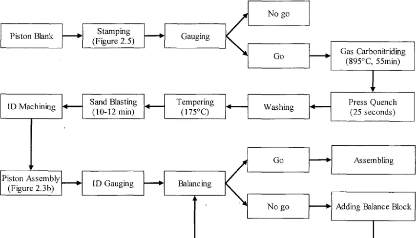
Figure 2.4 Flowchart of torque converter piston fabrication. 16
Figure 2.5 Five stage stamping operation of a torque converter piston, (a) Piston blank; (b) piston at stamping stage 1; (c) at stamping stage 2; (d) at stamping stage 3; (e) at
stamping stage 4; and (f) at stamping stage 5 17
Figure 2.6 A press-quench die. (a) Front view of a press-quench die; (b) magnified view
of the die edge. Courtesy of Toledo Machining Plant, Toledo, Ohio U.S.A 18
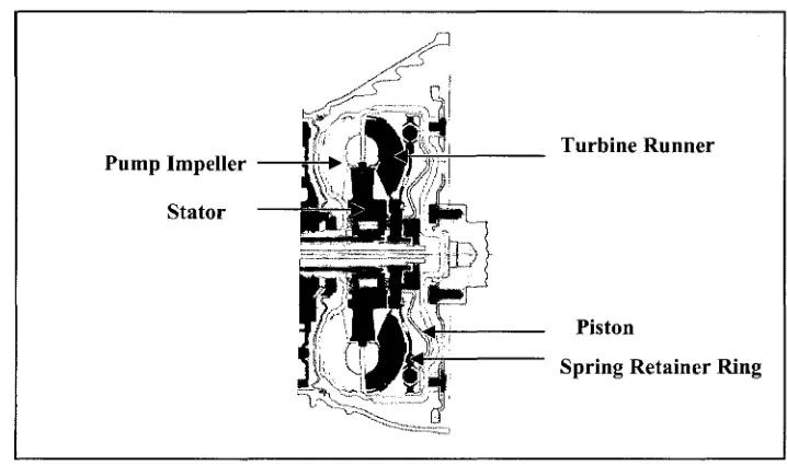
Figure 2.7 Schematic diagram of a torque converter assembly including the stator, impeller, turbine, spring retainer ring, and torque converter piston. Courtesy of Chrysler
LLC, Auburn Hills, Michigan U.S.A 19
Figure 2.8 Characteristics of a typical stress-strain curve obtained from a tension test....21
Figure 2.9 The dimension expansion and contraction of steel upon cooling 22
Figure 2.10 Illustration of two-dimensional plunge grinding operation on straight
surface 25
Figure 2.11 Schematic of material ground from a distorted gear tooth after case hardening
treatment 26
Figure 2.12 Three types of grinding stress distributions 26
Figure 2.13 Temperature difference during transformation-free quenching of an ideal
linear-elastic cylinder 28
Figure 2.14 Development of longitudinal transformation stresses in an ideal linear-elastic
Figure 2.15 Combined thermal and transformation stresses during quenching of an ideal
linear-elastic cylinder that transformations from austenite to martensite 30
Figure 2.16 Illustration of the Bragg relation 32
Figure 2.17 Definition of the axis and the direction of measurement 34
Chapter 3
Figure 3.1 Schematic of experimental procedures for piston and Navy C-ring
specimens 35
Figure 3.2 D8 Discover x-ray diffraction system at Bruker AXS Inc., MI, USA 37
Figure 3.3 Geometry of the D8 Discover with HI-STAR area detector. Courtesy of
Bruker AXS Inc., Michigan, USA 37
Figure 3.4 Navy C-ring's geometry and distortion measurement positions 38
Figure 3.5 Torque converter piston geometry and distortion measurement positions, (a) Front view of piston with lockup surface highlighted in pink; (b) Half cross section of piston showing ID measurement positions at -11 mm and -15 mm from the lockup
surface 39
Figure 3.6 Nitriding/nitrocarburizing furnace used in the gas ferritic nitrocarburizing (processes a-d) of the Navy C-rings and torque converter pistons at Woodworm Inc., Detroit, Michigan U.S.A. (a) Small pit-type furnaces used for gas ferritic nitrocarburizing
and nitriding; (b) Load of pistons after gas ferritic nitrocarburizing 41
Figure 3.7 Schematic module of gas ferritic nitrocarburizing process 42
Figure 3.8 Ion nitriding/nitrocarburizing of low-density sintered metal products at Advanced Heat Treat Co., Monroe, Michigan U.S.A. (a) Work parts under plasma glow in a furnace; (b) A load of sintered metal products after ion ferritic nitrocarburizing 43
Figure 3.9 A vacuum furnace used at Woodworth Inc., Detroit, Michigan U.S.A. (a)
Outside view of the vacuum furnace; (b) Inside view of the vacuum furnace 43
Figure 3.10 Schematic of a gas ferritic nitrocarburizing furnace with integrated water base q u e n c h i n g . Courtesy of Trutec Industries, Inc., Springfield, Ohio
U.S.A 44
Figure 3.11 Schematic flowchart of carbonitriding and quenching processes. Courtesy of
Figure 3.12 Instruments for metallographic analyses, (a) A light optical microscope; (b)
A microindentation hardness tester 46
Figure 3.13 A scanning electron microscope for microstructure analyses 47
Figure 3.14 A PRISMO Coordinate measuring machine (CMM). Courtesy of Chrysler
LLC, Auburn Hills, Michigan U.S.A 49
Figure 3.15 Example plot of flatness measurements obtained using CMM; 1-NC C-ring
sample after gas ferritic nitrocarburizing (process d, 595 °C/4 hrs) 50
Figure 3.16 Example plot of total flatness measurements obtained using CMM; piston
after ion ferritic nitrocarburizing (process e, 560 °C/15 hrs) 51
Figure 3.17 Example plot of flatness taper measurements obtained using CMM; piston
after ion ferritic nitrocarburizing (process e, 560 °C/15 hrs) 52
Figure 3.18 Location of surface residual stress measurement, (a) Measured at the lockup surface of a piston sample; (b) Measured at the thickest OD section of a C-ring
sample 53
Chapter 4
Figure 4.1 Pole figure of stamped SAE 1010 plain carbon steel for torque converter
piston 54
Figure 4.2 Optical micrographs of piston sample, gas carbonitriding at 850 °C for 4 hrs, with a subsequent 100 °C oil quenching and 190 °C tempering (process k). (a)
Microstructure at the martensitic case; (b) Microstructure at the core 55
Figure 4.3 Microstructure of the gas ferritic nitrocarburized piston (process a, 510 °C / 15
hrs) 56
Figure 4.4 Microstructure of the gas ferritic nitrocarburized piston (process b, 540 °C / 10
hrs) 56
Figure 4.5 Microstructure of the gas ferritic nitrocarburized piston (process c, 565 °C / 5
hrs) 56
Figure 4.6 Microstructure of the gas ferritic nitrocarburized piston (process d, 595 °C / 4
hrs) 56
Figure 4.7 Microstructure of the ion ferritic nitrocarburized piston (process e, 560 °C / 15
Figure 4.8 Micro structure of the ion ferritic nitrocarburized piston (process /, 525 °C / 24
hrs) 57
Figure 4.9 Microstructure of the gas ferritic nitrocarburized piston (process g, 525 °C / 52
hrs) 58
Figure 4.10 Microstructure of the gas ferritic nitrocarburized piston (process h, 570 °C / 4
hrs) 58
Figure 4.11 Microstructure of the vacuum ferritic nitrocarburized piston (process /, 580
°C/ 10 hrs) 58
Figure 4.12 Microstructure of the gas ferritic nitrocarburized piston (process j , 580 °C / 2
hrs) 58
Figure 4.13 Compound layer thicknesses of pistons versus gas ferritic nitrocarburizing
temperature 60
Figure 4.14 Variation of compound layer thickness with nitrocarburizing temperature (a,
b, e,f, and i) 61
Figure 4.15 Optical micrographs of C-ring samples, gas ferritic nitrocarburizing at 540 °C for 10 hrs (process b). (a) 1-NC C-ring series; (b) 2-NC C-ring series; (c) 3-NC C-ring
series; (d) 4-NC C-ring series 62
Figure 4.16 Microstructure of 5-NC C-ring (gas ferritic nitrocarburizing a, 510 °C / 15
hrs) 63
Figure 4.17 Microstructure of 5-NC C-ring (gas ferritic nitrocarburizing b, 540 °C / 10
hrs) 63
Figure 4.18 Microstructure of 5-NC C-ring (gas ferritic nitrocarburizing c, 565 °C / 5
hrs) 63
Figure 4.19 Microstructure of 5-NC C-ring (gas ferritic nitrocarburizing d, 595 °C / 4
hrs) 63
Figure 4.20 Microstructure of 5-NC C-ring (ion ferritic nitrocarburizing e, 560 °C / 15
hrs) 64
Figure 4.21 Microstructure of 5-NC C-ring (ion ferritic nitrocarburizing/, 525 °C / 24
Figure 4.22 Microstructure of 5-NC C-ring (gas ferritic nitrocarburizing g, 525 °C / 52
hrs) 64
Figure 4.23 Microstructure of 5-NC C-ring (gas ferritic nitrocarburizing h, 570 °C / 4
hrs) 64
Figure 4.24 Microstructure of 5-NC C-ring (vacuum ferritic nitrocarburizing i, 580 °C /
10 hrs) 64
Figure 4.25 Microstructure of 5-NC C-ring (gas ferritic nitrocarburizing j , 580 °C / 2
hrs) 64
Figure 4.26 Compound layer thickness of both piston and 5-NC C-ring specimens for
various ferritic nitrocarburizing processes (a-j) 65
Figure 4.27 SEM micrographs of piston sample, (a) Gas ferritic nitrocarburized piston, process a (510 °C / 15 hrs); (b) Ion ferritic nitrocarburized piston, process e (560 °C / 15
hrs) 66
Figure 4.28 Effect of compound layer thickness on microhardness {a, b, e,f, and /) 68
Figure 4.29 Hardness profiles of pistons after various ferritic nitrocarburizing processes
{a, b, e, f, and i) 69
Figure 4.30 Variation of hardness with distance below the surface for a carbonitrided
piston 70
Chapter 5
Figure 5.1 OD change of C-rings as a function of nitrocarburizing/carbonitriding
temperature {a-d, and k) 77
Figure 5.2 ID change of C-rings as a function of nitrocarburizing/carbonitriding
temperature {a-d, and k) 77
Figure 5.3 Gap change of C-rings as a function of nitrocarburizing/carbonitriding
temperature {a-d, and k) 78
Figure 5.4 Flatness change of C-rings as a function of nitrocarburizing/carbonitriding
Figure 5.5 ID change of pistons as a function of nitrocarburizing/carbonitriding
temperature (a-d, and k) 79
Figure 5.6 Flatness change of pistons as a function of nitrocarburizing/carbonitriding
temperature (a-d, and k) 80
Figure 5.7 OD change of nitrocarburized C-rings as a function of nitrocarburizing
temperature (a-d) 81
Figure 5.8 ID change of nitrocarburized C-rings as a function of nitrocarburizing
temperature (a-d) 81
Figure 5.9 Gap change of nitrocarburized C-rings as a function of temperature (a-d).. ..82
Figure 5.10 Flatness change of nitrocarburized C-rings as a function of nitrocarburizing
temperature (a-d) 83
Figure 5.11 OD change of C-rings as a function of nitrocarburizing temperature (f, g, i
and;) 84
Figure 5.12 ID change of C-rings as a function of nitrocarburizing temperature (f, g, i and
j) 84
Figure 5.13 Gap change of C-rings as a function of nitrocarburizing temperature (f, g, i
and;) 85
Figure 5.14 Flatness change of C-rings as a function of nitrocarburizing temperature (f, g,
i and;') 85
Figure 5.15 ID change ( @ - l l mm) of pistons as a function of nitrocarburizing
temperature (f, g, i and;') 86
Figure 5.16 ID change (@-15 mm) of pistons as a function of nitrocarburizing
temperature (f, g, i and j) 87
Figure 5.17 Total flatness change of pistons as a function of nitrocarburizing temperature
(/",£,/and/) 87
Figure 5.18 Flatness taper change of pistons as a function of nitrocarburizing temperature
(f, g,i and j) 88
Figure 5.19 OD change of C-rings as a function of nitrocarburizing temperature (e, h, and
Figure 5.20 ID change of C-rings as a function of nitrocarburizing temperature (e, h, and
0 89
Figure 5.21 Gap change of C-rings as a function of nitrocarburizing temperature (e, h,
and /) 90
Figure 5.22 Flatness change of C-rings as a function of nitrocarburizing temperature (e, h,
and i) 90
Figure 5.23 ED change of pistons as a function of nitrocarburizing temperature (e, h, and
i) 91
Figure 5.24 Total flatness change of pistons as a function of nitrocarburizing temperature
(e, h, and /) 92
Figure 5.25 Flatness taper change of pistons as a function of nitrocarburizing temperature
(e, h, and /) 92
Chapter 6
Figure 6.1 Comparison of the effects of nitrocarburizing temperature on the residual
stresses and compound layer thicknesses for the 5-NC C-ring samples 96
Figure 6.2 Residual stresses of piston samples for nitrocarburizing and carbonitriding...98
Figure 6.3 Variation of residual stress in the nitrocarburized C-ring and piston samples
(a-d) 99
Figure 6.4 Variation of residual stresses and case hardness with nitrocarburizing
temperature for pistons 100
Figure 6.5 Variation of residual stresses versus microhardness for nitrocarburized pistons
LIST OF ABBREVIATIONS
CMM
EDM
OD
ID
Ms
SEM
XRD
FCC
BCC
Aci
coordinate measuring machine
electrical discharge machining
outside diameter
inside diameter
martensite start temperature
scanning electron microscopy
x-ray diffraction
face-centered cubic
body-centered cubic
I. INTRODUCTION
The term "Surface Engineering" is defined in the ASM Handbook as "treatment
of the surface and near surface regions of a material to allow the surface to perform
functions that are distinct from those functions demanded from the bulk of the material"
[1]. Surface engineering has been divided into six sectors by the Surface Engineering
Division of the Institute of Materials, Minerals and Mining: high value;
energy/aerospace; transport; packaging; white goods; biomedical [2]. As pointed out by
Rickerby [3], many of our modes of transport are improved by surface engineering. For
example, coatings are applied to reduce rolling and frictional losses within mechanical
assemblies in order to both extend component lifetimes and minimize total lifecycle
energy consumption of automobiles. Surface engineering has also been utilized to help
overcome corrosion problems that once plagued the automotive industry [3].
Surface engineering can be performed through the following methods: (1)
changing the surface metallurgy, such as flame hardening and laser melting; (2) changing
the surface chemistry, for example, ferritic nitrocarburizing and carbonitriding; (3)
adding a surface layer or coating, for instance, organic coatings and electroplating. These
methods ensure that the desired characteristics of surface-engineered components can be
obtained, such as improved corrosion and wear resistance, enhanced fatigue and
toughness, and improved mechanical properties [4]. Among these methods of surface
engineering, both the carbonitriding and nitrocarburizing processes have been
extensively adopted by the automotive industry to impart a hard and wear resistant case
to steel components while maintaining the tough interior to resist the impact that occurs
during operation [5].
Carbonitriding is generally regarded as a modified carburizing process, in which
ammonia (NH3) is added into the carburizing atmosphere to release nitrogen with the
ability to diffuse into the austenite of steel simultaneously with carbon [6-9]. During
carbonitriding, the austenite composition is changed and the hard and wear resistant
components are carbonitrided in the current production cycles, such as the pistons and
retainer rings for the torque converters of transmissions [8].
Chrysler LLC uses a carbonitriding process to improve the hardness and wear
resistance of torque converter pistons [11]. The torque converter piston is primarily used
to engage the converter case to lock the impeller and the turbine during the manipulation
of the torque converter, ensuring complete power transfer and reducing fuel consumption
[12]. The control principle of the torque converter piston defines the importance of
accurate inside diameter, total flatness, and flatness taper of the lockup surface for the
normal operation of the torque converter [11]. Although the desired hardness and wear
resistant surface properties were achieved using the carbonitriding process, there were
issues associated with the quenching step to form martensite, especially the size and
shape distortion in the final component. The phenomenon of surface oxidation and
nonuniform surface hardness also accompanied the process. In order to meet the
dimensional specifications, the surface defects resulting from carbonitriding and
quenching were corrected using finish grinding, a technique in which excess material is
removed from the surface of the steel [13]. However, this additional manufacturing step
contributes to longer production times and higher part costs, and also raises the risk of
grind burns.
Gaseous ferritic nitrocarburizing has been investigated as a potential replacement
for carbonitriding for minimizing dimensional distortion in the torque converter pistons
[14-16]. Ferritic nitrocarburizing is a modified form of nitriding, which involves the
diffusion of both nitrogen and carbon into the surface of ferrous materials at temperatures
completely within the ferrite phase field [8, 10, 17, 18]. The low-temperature
nitrocarburizing process contributes to the absence of a phase transformation from ferrite
to austenite or the need for further quenching to form martensite; consequently, distortion
resulting from either the released induced stresses, the thermal shock of quenching, or the
incomplete transformation to martensite can be significantly reduced [17, 19]. The
surface oxidation and nonuniform surface hardness associated with quenching can also
improve surface characteristics, can be eliminated, which will contribute to a shorter
production cycle and lower part costs.
In the present study, gas, ion and vacuum nitrocarburizing using different heat
treatment schedules were investigated as well as carbonitriding using current production
practice for SAE 1010 plain carbon steel. Two types of specimens were used for the
study, namely Navy C-rings and torque converter pistons. Navy C-rings are specially
designed specimens used to examine distortion in heat-treated components [20]. Navy
C-rings with thicknesses between 2.8 mm and 19.05 mm were used to examine the effects
of specimen thickness and heat treatment process on distortion. The distortions in the
C-ring specimens are compared to those found in torque converter pistons that were
subjected to the same heat treatment process.
The intent of this work focused mainly on the comparison of the effects of various
ferritic nitrocarburizing and carbonitriding processes on dimensional distortion (size and
shape) and surface residual stresses. The distortion was correlated with the
microstructural changes and surface residual stresses resulting from the heat treatment.
Optical microscopy (OM) and scanning electron microscopy (SEM) were used to
evaluate the interrelationships between the microstructure and properties within the
specimens and the nitrocarburizing or carbonitriding processes applied. X-ray diffraction
(XRD) techniques were used to characterize the residual stresses in the surface of the
nitrocarburized and carbonitrided specimens, and to analyze the surface phase
composition and texture for the different nitrocarburizing processes. Vickers hardness
testing was performed on cross sections of the nitrocarburized specimens to evaluate the
hardness of the compound layer and the underlying diffusion zone.
Based on the analyses and comparisons of the various ferritic nitrocarburizing and
carbonitriding processes mentioned above, an appropriate heat treatment process and
treatment schedule will be put forward, which will reduce distortion and manufacturing
II. LITERATURE REVIEW
The objective of this chapter is to introduce the various diffusion methods of
surface hardening, include the carburizing, carbonitriding, nitriding, and nitrocarburizing
processes. Special attention is given to a comparison of the carbonitriding and
nitrocarburizing procedures, with respect to the dimensional distortion and residual
stresses that result from each process.
2.1 Surface Hardening of Steel
Surface hardening is a heat treatment method used to improve the wear resistance
of parts without affecting the more soft, tough interior of the part [5, 8]. For applications
where low or moderate core properties, together with a high degree of surface hardness
are desired, the combination of a hard surface and softer interior is useful, e.g., a cam or
ring gear. Surface hardening also helps to reduce distortion and eliminate cracking that
might be induced by through hardening, especially in large sections of low-carbon and
medium-carbon steels [21].
As noted by Davis [8], there are three different methods for surface hardening:
thermochemical diffusion methods; applied energy or thermal methods; and surface
coating or surface-modification methods. The difference between the first two
approaches is that the diffusion methods modify the chemical composition of the surface
using hardening species such as carbon and nitrogen, whereas the latter alters the surface
metallurgy without modifying the chemical composition [8]. Carburizing, carbonitriding,
nitriding and nitrocarburizing processes from the first group of diffusion methods will be
briefly reviewed in this section, with an emphasis placed on comparing carbonitriding
and nitrocarburizing with various heat treatment procedures.
2.1.1 Carburizing
Of the case hardening treatments, carburizing is by far more extensively used than
the carbonitriding, nitriding and nitrocarburizing processes [22]. Carburizing is achieved
by adding carbon to the surface of low-carbon steels at elevated temperatures in the
martensitic microstructure [8, 23, 24]. Carburizing can be performed at temperatures
between 790 to 1090 °C, but in production practice, it is generally done at temperatures
between 850 and 950 °C. Higher temperatures reduce the effective life of furnace
equipment; lower temperatures slow the completion of the carburizing procedure [22,
23].
Carburizing produces a hardness gradient below the surface of the material owing
to the decreasing carbon content with depth. It also produces compressive residual
stresses at the surface due to the volume expansion resulting from the martensitic
transformation [9]. The main objective of carburizing is to provide a hard high-carbon
martensitic surface with good wear and fatigue resistance, along with compressive
surface residual stresses that contribute to longer service life in ferrous engineering
components [22, 25]. The microstructure of the carburized case is mainly composed of
plate martensite and retained austenite, whereas the core contains lath martensite, or for
larger components, bainite or ferrite and pearlite [9].
Carburizing can be performed using gas carburizing, plasma (ion) carburizing,
vacuum carburizing, salt bath carburizing, and pack carburizing. Different methods are
classified according to their carbon sources, which originate from a gaseous environment
(atmospheric gas, plasma and vacuum), a liquid salt bath, or a solid carbonaceous
compound [8, 22]. Gas carburizing is the most widely used method of the various
carburizing processes while plasma and vacuum carburizing are also useful due to the
absence of oxygen in the furnace atmosphere [8]. Traditionally, gas carburizing
atmospheres are produced by combustion of natural gas or other hydrocarbon gas in
exothermic or endothermic gas generators. The components of the atmosphere may be
any of several carrier gases, principally composed of CO, CO2, CH4, H2, H2O and N2 [21,
24]. It should be noted that the nitrogen component in the atmosphere is inert, and acts
only as a diluent [24]. The carburizing time depends on the desired depth of diffusion.
2.1.2 Carbonitriding
Carbonitriding is being used increasingly as a modified carburizing process in
difference between carbonitriding and carburizing is the addition of ammonia (NH3) into
the carbonitriding atmosphere. Nascent nitrogen forms by the dissociation of ammonia
and diffuses into the steel simultaneously with carbon [6, 8, 9]. Similar to carburizing,
the austenite composition is changed and high surface hardness is produced by quenching
to form martensite[10], though the quenching process is less severe than carburizing [8].
Besides the improved surface hardness, carbonitriding can also increase the effective
service life of components. As noted by Gesser et al. [26], the average life of tools after
carbonitriding can be extended by three or four times compared to uncarbonitrided tools
in life tests.
Carbonitriding has more strict requirements for application than carburizing
because deeper case depths require prohibitive time cycles and higher temperatures and,
moreover, the control of nitrogen addition in the furnace atmosphere is more difficult
than that of carbon [8, 23]. Typically, carbonitriding is conducted at lower temperatures
ranging between 705 and 900 °C and for a shorter processing time than carburizing. The
reduced process time and temperature, together with the fact that the nitrogen restrains
the diffusion of carbon, results in a shallower iron-carbon-nitrogen compound layer at the
surface of steel than usual carburizing practice. The layer thickness ranges from 0.075 to
0.75mm [10, 27]. The exact case composition depends on the process parameters of
temperature, time, atmosphere composition, and the type of steel [6, 8]. The preferred
case depth of carbonitrided steels is determined by the core hardness and surface
requirements of the component. Case depths up to 0.75 mm may be applied to
components such as cams for resisting high compressive loads. Many factors will
promote the uniformity of case depth for carbonitriding, including uniform processing
temperature, accurate time control, adequate circulation and replenishment of the furnace
atmosphere, and reasonable distribution of the furnace charge [6, 8, 23].
The concentrations of carbon, nitrogen, and other alloying elements in the case, as
well as its phase composition, will influence the hardenability of steel [28]. Nitrogen
enhances the hardenability of steel by lowering the critical cooling rate, and improves the
resistance of steel to softening at slightly elevated temperatures [9, 29]. Similar to
to ferrite and pearlite and lowers the martensite start temperature Ms. [23]. Excessive
nitrogen may cause a large amount of retained austenite and case porosity during longer
processing times [6, 27].
While carbonitriding can be performed using a salt bath, in a furnace gas
atmosphere, or by plasma processing [8], the emphasis in this section is placed on the gas
carbonitriding process. The carbonitriding atmosphere is generally composed of a
mixture of carrier gas, enriching gas, and ammonia. The atmosphere can be controlled
by producing a carrier gas with constant chemical composition and dew point, and by
altering the proportion of the enriching gas and ammonia to maintain the desired
composition of nitrogen and carbon in the carbonitrided case [6]. The exact gas
composition is usually measured through flowmeters, and the gases may be premixed
just before they enter the furnace. A typical carbonitriding atmosphere contains 2-12%
ammonia within a standard gas carburizing atmosphere [6, 8]; the ammonia is anhydrous
ammonia of 99.9+% purity [23].
Depending on the allowable distortion and metallurgical requirements, as well as
the type of furnace equipment used, carbonitrided components can be quenched in water,
oil or gas. Water quenching is usually applied to low-carbon steel components when the
resulting distortion is acceptable. It is optimum for the parts to be directly transferred
from the carbonitriding furnace into the air before quenching to avoid possible
contamination of the furnace atmosphere by water vapor. Oil quenching is generally used
to obtain full hardness with less distortion. It is generally performed at approximately 40
to 105 °C. It is worthwhile noting that quenching oils with a low capacity for dissolving
water are desirable to achieve the maximum effectiveness in quenching. Gas quenching
is primarily used for reducing distortion, and usually adapted to small-mass components
[6, 8, 23].
Although the desired surface properties are obtained by carbonitriding, other
issues associated with this process need to be considered. During carbonitriding and its
subsequent quenching process, the phase transformation from face-centered cubic
austenite to the more open body-centered structures of ferrite and martensite results in
cause serious assembly issues such as binding or "freezing" in components with high
tolerance specifications [6, 10]. Moreover, surface oxidation takes place during
processing, and nonuniform surface hardness results from the delayed heat transfer
between the quenching die and the workpiece.
Tempering is often performed after carbonitriding by reheating a
quench-hardened ferrous alloy to a temperature below the eutectoid temperature (AcO for a fixed
length of time, then cooling to room temperature at a suitable rate. [31]. Low-carbon steel
components are usually tempered in the range of 135-175 °C to stabilize austenite and
minimize dimensional distortion [8]. Tempering is primarily used to transform the
unstable and brittle as-quenched martensite into a more stable tempered martensite,
which increases ductility, yield strength, and toughness, as well as increases the grain
size of the matrix [32, 33].
2.1.3 Nitriding
Derived from nitrocarburizing, nitriding is a ferritic thermochemical diffusion
method being used in many industrial applications. Similar to carbonitriding, nitriding
changes the surface composition by diffusing atomic nitrogen into the steel surface to
obtain a hard and wear resistant surface [34-36]. However, nitriding is usually carried out
at comparatively low temperatures, ranging from 495 to 565 °C for all steels. Because at
these temperatures, nitrogen is added into ferrite instead of austenite, the body-centered
cubic ferrite does not change its crystallographic structure or transform into the
face-centered cubic austenite. Moreover, because no rapid cooling or quenching occurs during
the complete nitriding procedure, dimensional changes resulting from the phase change
from austenite to martensite are significantly reduced [17, 23]. All these factors
determine how nitriding of steels can produce less dimensional distortion and
deformation than the traditional carburizing processes. Only slight volumetric changes of
the steel surface exist as a result of the nitrogen diffusion [34].
Several types of nitriding methods have been developed; it can be performed in a
the nitriding atmosphere is ammonia, sometimes diluted with additional gases such as
nitrogen and hydrogen [9].
Generally, the nitriding process produces a thin compound layer at the surface,
with a relatively thick (300-500 (J,m) and hard (900-1200 HV) diffusion zone underneath
[37]. The compound layer is also known as the white layer because it etches white in
metallographic preparation. The hard and brittle compound layer contains two intermixed
phases, epsilon (s) and gamma prime (y'). The region below the compound layer is called
the "diffusion zone", and consists of stable nitrides formed by the reaction of nitrogen
with nitride-forming elements [17]. The solubility of nitrogen in iron leads to the
formation of a solid solution with ferrite at nitrogen contents up to about 6%. When the
nitrogen content is about 6%, gamma prime Fe4N is produced. When the nitrogen content
is greater than 8%, the epsilon compound Fe3N is produced. The carbon content also
influences the composition of the compound layer. Higher carbon contents of the steel
lead to the formation of more s-phase, whereas a lower carbon content is responsible for
an increase in the y' phase. The thickness of the compound layer depends on the nitriding
time, temperature, and gas composition [17, 34].
2.1.4 Ferritic Nitrocarburizing
Nitrocarburizing is a modified form of nitriding, which involves the addition by
diffusion of both nitrogen and carbon to the surface of ferrous or non-ferrous materials at
elevated temperature. Nitrocarburizing can be classified into ferritic nitrocarburizing and
austenitic nitrocarburizing, depending on the type of phase transitions and material
properties obtained. Ferritic nitrocarburizing is primarily used to improve the surface
properties of low alloy steels by producing a hard, wear and corrosion resistant surface
without changing the core properties. Austenitic nitrocarburizing is usually applied to
plain carbon steels to upgrade both the surface and the core properties [38, 39]. The
emphasis of this section is on the ferritic nitrocarburizing process.
Ferritic nitrocarburizing takes place completely within the ferrite phase field
below the Aci temperature, in the range of 525 and 650 °C [8, 18]. In this procedure,
iron simultaneously with carbon and gets trapped within the interstitial lattice spaces in
the steel structure [8, 17, 40]. The nitrogen is considerably more soluble in steel than
carbon and therefore mainly diffuses into the material, while the carbon forms iron or
alloy carbide particles at, or near, the surface [41].
Typically, nitrocarburizing imparts a nitrogen-rich compound layer at the surface
of the material, and an underlying diffusion zone [8, 17]. Similar to nitriding, the
compound layer for nitrocarburizing consists predominantly of the same two
metallurgical phases of both epsilon and gamma prime nitrides. The single-phase epsilon
(s) iron-carbonitride (Fe2-3(N,Q) is a ternary compound of iron, nitrogen and carbon with
a hexagonal structure. Both the carbon content of the steel and the presence of
nitride-forming elements on the steel surface will affect the balance of the epsilon and gamma
prime phases. The composition of the process atmosphere is another factor influencing
the phase composition [8, 19]. The compound layer is usually 10 to 40 itm thick,
providing good physical and chemical properties against galling, scuffing, wear and
corrosion [10, 42]. The diffusion zone, which consists of iron (and alloy) nitrides and
dissolved nitrogen, improves fatigue endurance and case hardness [4, 8, 43]. The
diffusion depth of nitrogen is directly responsible for the improvement in fatigue
properties, particularly in carbon and low-alloy steels [18, 44]. The compound-diffusion
layer may contain varying amounts of gamma prime (y'), e-phase, cementite and various
alloy nitrides and carbides, depending on the nitride-forming elements in the material,
temperature, nitrocarburizing time, and the composition of the atmosphere. The total
thickness of the compound layer and the diffusion zone can reach 1mm [8, 18, 45].
A comparison of the typical metallographic structures of nitrocarburized and
carbonitrided steel is shown in Figure 2.1 [46]. The ferritic nitrocarburizing was
performed at a lower temperature of 570 °C, and nitrogen is the predominant element in
the epsilon compound layer and diffusion zone. Whereas the carbonitriding was carried
out at a higher temperature of 850 °C, and carbon predominates in the formation of the
martensitic layer. The thickness difference of the compound layer between the two is also
obvious, with only a very thin compound layer being formed on the steel surface after
Distance from surface, urn Distance from surface, iim
Figure 2.1 Comparison between the nitrocarburizing and carbonitriding [46].
Besides the improvements to the surface characteristics, ferritic nitrocarburizing
can also reduce the risk of distortion. Because the procedure is carried out at a low
temperature, the steel microstructure remains in the ferritic region and no phase
transformation occurs. Moreover, the subsequent quenching process commonly used to
form martensite is eliminated. As a result, distortion resulting from either the released
induced stresses, the thermal shock of quenching, or the incomplete transformation to
martensite can be significantly reduced [17, 19, 47]. Additional processing operations,
such as finish grinding to correct distortion, can be eliminated, which helps to lower
production times and part costs. Previous studies by the research group at the University
of Windsor have demonstrated the advantages of nitrocarburizing over carbonitriding
with respect to the dimensional changes in a stamped automotive component fabricated
from SAE 1010 plain carbon steel [14, 48].
The nitrocarburizing atmosphere is predominantly composed of ammonia and
some carbon- and oxygen-bearing gases [9]. The carbon in the nitrocarburizing
atmosphere is an s-phase stabilizer, which helps to form the compound layer at much
lower nitrogen contents. The oxygen or combined oxygen additions in the
[18]. Another important function of oxygen is to create a surface oxide layer on top of the
diffusion-formed case to resist corrosion [19].
Several different methods of accomplishing the ferritic nitrocarburizing process
have been developed in the last few decades, including liquid procedures, gaseous
methods, and ion (plasma) procedures. The gas, vacuum, and ion ferritic nitrocarburizing
processes are detailed in the following sections.
2.1.4.1 Gas Ferritic Nitrocarburizing
Gas ferritic nitrocarburizing as an industrial process was patented by Lucas
(Industries) Ltd. in 1961, and has received serious industrial attention since the early
1970s [42, 49]. Gas nitrocarburizing is performed just below the austenite range for the
iron-nitrogen system, in a temperature range of 450-590 °C [18, 50]. Parts are generally
treated at about 570 °C for 1 to 3 hours [8]. A number of gas mixtures are used for
commercial production; a typical industrial gas nitrocarburizing atmosphere is comprised
of ammonia (NH3), hydrocarbon gas (e.g. methane or propane), and an endothermic gas
[19].
Gas nitrocarburizing is a significant improvement over the conventional liquid
approach. The cost for gas nitrocarburizing is much lower, and the whole process is
nontoxic. The compound layer formed after gas nitrocarburizing is denser and its surface
is not eroded. Further, it is easier to control the gas atmosphere and to optimize the
structure and composition of the nitride layer, which make the automatic batch
production possible [51].
2.1.4.2 Vacuum Ferritic Nitrocarburizing
Heat treating in vacuum commonly refers to a process carried out in a space with
a highly reduced gas density, rather than a space entirely devoid of matter. The primary
objective of using vacuum for heat treating is to avoid the surface oxidation that occurs
during heat treatment in air. It can be accomplished in several ways. One is to replace the
air in the treatment furnace with a protective atmosphere that contains almost no oxygen,
such as by using nitrogen as the inert atmosphere. Another way is to reduce the amount
the oxidation level of the material [52, 53]. The latter approach is applicable to vacuum
nitrocarburizing.
Vacuum nitrocarburizing is a subatmospheric nitrocarburizing process that uses a
basic atmosphere of 50% ammonia / 50% methane, as well as controlled oxygen
additions of up to 2% [31, 54]. Vacuum processing has several predominant advantages:
it produces a very pure starting atmosphere; and it eliminates the need for a nitrogen
purge. It is also a more environmentally friendly process; no fumes or exhaust gases are
released during vacuum nitrocarburizing [42, 55]. The cold vacuum furnaces are also
favorable to smaller heat accumulation and faster heating and cooling performance. On
the other hand, there are problems associated with vacuum nitrocarburizing, such as the
greater adsorption of gases and water vapor on both the cooled furnace walls, as well as
the insulation after opening of the furnace [52].
2.1.4.3 Ion Ferritic Nitrocarburizing
Ion (plasma) nitrocarburizing is a modified ion nitriding method that involves
glow discharge technology to add elemental nitrogen to the work surface for subsequent
diffusion into the material [56]. Ion nitrocarburizing is generally conducted near 570 °C
to form a compound layer greater than 5 (im and a surface hardness higher than 350 HV
[8, 50]. The composition of the plasma atmosphere is a mixture of hydrogen, nitrogen
and a carbon-bearing gas, such as methane (natural gas) or carbon dioxide [8]. Control of
the gas flow to obtain the appropriate phases during ion ferritic nitrocarburizing is not
simple, due to the difficulties in measuring the gas decomposition, nitrogen potential, and
the content of free oxygen. Usually, it is accomplished by controlling the gas ratios of the
nitrogen, hydrogen, and hydrocarbon gases in the atmosphere [19].
The compound layer produced by ion nitrocarburizing is usually composed of e
and y' phases for low carbon-level atmospheres [8, 18]. Previous research has indicated
that a monophase structure is favored for improving tribological properties; other phases
existing in the compound layer can help to enhance the corrosion resistance [57, 58].
Ion nitrocarburizing is an environmentally friendly process that produces no toxic
explosion accompanying it [8, 18]. Ion nitrocarburizing is also an economical heat
treatment method that accelerates the penetration of nitrogen and carbon, contributing to
reduced processing times and energy consumption [59, 60]. Moreover, the plasma
processes offer several additional possibilities for parameter variation, which
consequently provide a better control of the layer structure, morphology, and service
characteristics [39, 61]. Ion nitrocarburizing has been widely applied to various materials
such as carbon steels, alloy steels, tool steels, stainless steels, cast irons, and sintered
materials [62, 63]. However, the use of direct plasma processes can lead to sputtering
and accordingly decrease the diffusion depth for a given time [64].
2.2 Navy C-Rings and Torque Converter Pistons
For some period of time, Navy C-ring specimens have been an important tool in
studying distortion of heat treated materials [20, 65]. The use of Navy C-rings can be
traced back to 1921, when they were first used by the US Navy in the inspection of class
5 tool steels [66]. Currently, there are no standard dimensions for Navy C-ring
specimens. Specimens are typically fabricated from the desired testing material and
machined into a variety of sizes. A simplified Navy C-ring sample used in a quench
distortion study and a modified Navy C-ring distortion test specimen are shown in Figure
2.2 [13, 67].
D '
, 0.5 in.
'
.£
I <
.
^
£
1.0 in.
1
* L
'
«<— 0.25 in. -0.5 in.
(a) (b)
Figure 2.2 Navy C-ring Geometry.
A torque converter piston is an important component of an automotive
transmission. The desired specifications for a piston used by Chrysler are as follows:
outside diameter (OD) of 260 mm, inside diameter (ID) of 62 mm and a weight of 1.8 kg
[11]. The geometry of a piston sample and an assembled unit are shown in Figures 2.3 (a)
and (b), respectively.
• ' &
4
(a) (b)
Figure 2.3 Torque converter piston and piston-retainer assembly.
(a) Torque converter piston; (b) Piston assembled with springs and retainer.
2.2.1 Fabrication of Torque Converter Pistons
The torque converter pistons are made from 2.8 mm thick sheets of cold-worked
SAE 1010 steel. The current manufacturing process for torque converter pistons consists
of three basic steps: surface hardening, press quenching, and tempering, as illustrated
Piston Blank Stamping
(Figure 2.5) Gauging
/ (
\ \
ID Machining
1
•
Sand Blasting (10-12 min) •«
Tempering (175°C)
'
Piston Assembly
(Figure 2.3b) ID Gauging Balancing 1 I
/
^ \
No go
Go
Washing
Go
No go
Gas Carbonitriding (895°C, 55min)
'r
Press Quench (25 seconds)
Assembling
Adding Balance Block
Figure 2.4 Flowchart of torque converter piston fabrication.
Beginning as circular blanks, the pistons go through a progressive five-stage
stamping operation to form the desired geometrical dimensions and shapes, Figure 2.5.
The qualified pistons will be selected by gauging and delivered to the subsequent case
hardening station.
Carbonitriding is applied to the pistons to improve the surface hardness and wear
resistance. After a pre-cleaning step to remove surface contaminants, the pistons are fed
into a rotary hearth furnace with an atmosphere mixture of natural gas, nitrogen and
ammonia. The carbonitriding temperature was set at 895 °C, and the furnace cycle time
for a batch of pistons is about 55 minutes. During processing, both nitrogen and carbon
are absorbed and diffused into the surface of pistons to enhance the surface hardness. The
heat treated components are then removed from the furnace and go through a press
quenching process. Press quenching can offer remarkable dimensional control, because
the workpiece is restrained in dies while the quenchant flows across the various parts of
the surface until the part is fully cooled to a predetermined temperature [68]. The pistons
quench medium maintained at a concentration of 9-11%. The quench bath temperature is
controlled at 50 °C, and forces up to 50 kN are used. A typical profile of a press-quench
die is shown in Figure 2.6. The surface hardness of pistons is remarkably improved upon
quenching by the formation of a martensitic case.
• " ^ • - ^ w — • " '
I.I) ( h i
t
t 4
$
.. - y
*
* *
*-- *
. . .. / *
(c) (d)
,' -•..•.-—'*:.
*..
•
*
•••-•H* *******
4
1
4 •
i '' '
>
s
• *
(e) (f)
Figure 2.6 A press-quench die. (a) Front view of a press-quench die; (b) magnified view of the die edge. Courtesy of Toledo Machining Plant, Toledo, Ohio U.S.A.
The pistons are then drained, washed, and dried prior to tempering. Tempering is
conducted to stabilize the austenite and minimize dimensional variations. Pistons are
reheated to 175 °C for 1 hour, before being removed from the furnace and transferred to
a cooling station, where they are cooled to ambient temperature. The pistons are then
subjected to a sand blasting operation for 10-12 minutes to remove the surface oxide
scale formed during the heat treatment. After grinding the inside diameter (ID) of piston
to meet the dimension specifications, each piston is joined together with a retainer and
springs using rivets, the assembled unit was shown in Figure 2.3(b). In the final stages of
production, the assembly undergoes two more quality inspections: ID gauging, and mass
balancing.
2.2.2 Pistons in Torque Converter
A torque converter is a modified form of fluid coupling, which is used to transfer
rotating power from a prime mover, such as an internal combustion engine or electric
motor, to a rotating driven load. Similar to basic fluid coupling, the torque converter
takes the place of a mechanical clutch, allowing the load to be separated from the power
source. The superiority of a torque converter over fluid coupling is that it can multiply
the torque when there is a substantial difference between input and output rotational
speed, thus providing the equivalent of a reduction gear [69, 70].
In a torque converter, there are at least three rotating elements: the pump impeller,
load; and the stator, which is interposed between the pump and turbine so that it can alter
oil flow returning from the turbine to the pump [70]. These elements are shown in Figure
2.7.
Figure 2.7 Schematic diagram of a torque converter assembly including the stator, impeller, turbine, spring retainer ring, and torque converter piston. Courtesy of Chrysler LLC, Auburn Hills, Michigan U.S.A.
When the impeller and turbine are rotating at almost the same speed, no torque
multiplication takes place, and the ratio of output torque to input torque equals to one. In
practice, however, there is an approximately 4-5% difference in rotational speed between
the turbine and impeller, which leads to energy losses. A lockup piston clutch is used to
prevent this problem. The lockup piston clutch consists of a piston, damper assembly,
and a clutch friction plate. The damper assembly, which contains a damper and several
coil springs, is used to transmit driving torque and absorb shock. The lockup piston
clutch is located between the front of the turbine and the interior front face of the shell.
Under the control of hydraulic valves, engaging and disengaging of the lockup clutch is
implemented by the difference in pressure on either side of the lockup clutch. Successful
engagement of the lockup piston clutch between the impeller and the turbine assembly
can substantially improve fuel economy and reduce operational heat and engine speed
2.3 Distortion
Distortion is an inevitable problem associated with thermal processing techniques,
especially for heat treatment procedures, due to high temperatures and severe thermal
gradients during heating and quenching. When parts are heat treated, unpredictable or
inconsistent change in size or shape is produced by the complex interaction between the
heat treating environment and the thermal-mechanical and metallurgical evolution in the
heat treated components [72].
2.3.1 Basic Distortion Mechanisms
There are three fundamental reasons accounting for the size and shape variations
of workpieces during heat treating [13, 73].
First of all, residual stresses may lead to shape distortion during heating once they
exceed the yield strength of the material. Materials containing residual stresses prior to
heat treatment will relieve those stresses during heat treatment. The relaxation of these
stresses is achieved when the existing residual stresses exceed the yield strength of the
material upon heating [68, 74]. A typical diagram illustrating the relationship of the stress
and strain for a tension test is shown in Figure 2.8 [75]. During the initial stages of the
tension test, elastic deformation of the material takes place. When the increased stress
becomes larger than the yield strength of the material, permanent plastic deformation
occurs. As the dimensional shape of the components is varied by plastic flow, the stresses
present in the material are gradually relieved. In general, the yield strength of a material
decreases as the heat treating temperature increases. Moreover, the extent of the resulting
plastic deformation depends on the magnitude and distribution of the stress field in the
Ultimate tensile alwRgth iVTS)
Fracture
Strain,s
Offoet
Figure 2.8 Characteristics of a typical stress-strain curve obtained from a tension test [75].
Secondly, thermal stresses resulting from the differential expansion associated
with the thermal gradients may produce plastic deformation when the stresses exceed the
yield strength of the material. If a part could be processed at the same heating rate
throughout the whole section, uniform expansion occurs and the part dimensions will be
maintained. However, in actual heat treatment practice, a thermal gradient exists across
the cross section of the part. Differential thermal expansion will cause sizable thermal
strains, whereby the first part of the component to be heated will expand earlier and
occupy a greater volume than the colder surrounding area, consequently leading to
thermal stresses within the components. When the thermal stresses exceed the yield
strength of the material, plastic deformation occurs [76]. These material movements are
associated with the heating rate applied, the coefficient of thermal expansion, and the
geometry and properties of the component.
Thirdly, phase transformations during heat treating result in volume changes;
these changes are constrained in the residual stress systems until the resulting stresses
exceed the yield strength of the material. When a steel part is heat treated, phase
transformations occur accompanied by their respective volume changes due to the
variation of the microstructure and carbon content in the steel. As an example, consider
the phase transformation of a ferrite/cementite microstructure during heating and cooling.
structure of the face-centered cubic (fee) austenite phase. On cooling, there is a
subsequent volume expansion. Variations in the linear dimensions of a steel under both
slow cooling and fast quenching conditions are shown in Figure 2.9 [67]. On slow
cooling, the steel component experiences a size distortion as its crystal structure changes
from the more densely packed fee austenite phase to the less densely packed
body-centered cubic (bec) ferrite phase. When the steel is treated at a faster cooling rate by
quenching, instead of forming ferrite, the even less densely packed body-centered
tetragonal structure of martensite will be produced. When the stresses resulting from
these volume changes exceed the yield strength of the material, dimensional deformation
takes place. As shown in the Figure 2.9, the steel contracts until the Ms temperature is
reached, at which point there is a volumetric expansion during martensite formation at
lower temperatures. The volume and shape variations are related to the heating rate, the
geometry of the component, and the phase volume change [13, 67, 77].
Temperature, "F
. „ 0 200 400 800 SOD 1000 120014001800
1.2
1.0
c O.B o
'M s & g 0.6 »
c
U.,4
0.2
0
0 100 200 300 400 500 800 700 600 §00 Temperature, CC
![Figure 2.1 Comparison between the nitrocarburizing and carbonitriding [46].](https://thumb-us.123doks.com/thumbv2/123dok_us/1463145.1179264/31.598.115.525.73.277/figure-comparison-nitrocarburizing-carbonitriding.webp)

![Figure 2.8 Characteristics of a typical stress-strain curve obtained from a tension test [75]](https://thumb-us.123doks.com/thumbv2/123dok_us/1463145.1179264/41.598.173.425.67.258/figure-characteristics-typical-stress-strain-curve-obtained-tension.webp)
![Figure 2.9 The dimension expansion and contraction of steel upon cooling [67].](https://thumb-us.123doks.com/thumbv2/123dok_us/1463145.1179264/42.599.219.406.367.651/figure-dimension-expansion-contraction-steel-cooling.webp)
![Figure 2.10 Illustration of two-dimensional plunge grinding operation on straight surface [81]](https://thumb-us.123doks.com/thumbv2/123dok_us/1463145.1179264/45.598.222.414.356.529/figure-illustration-dimensional-plunge-grinding-operation-straight-surface.webp)
![Figure 2.13 Temperature difference during transformation-free quenching of an ideal linear-elastic cylinder [86]](https://thumb-us.123doks.com/thumbv2/123dok_us/1463145.1179264/48.600.234.404.74.335/figure-temperature-difference-transformation-quenching-linear-elastic-cylinder.webp)
![Figure 2.14 Development of longitudinal transformation stresses in an ideal linear-elastic cylinder after quenching [86]](https://thumb-us.123doks.com/thumbv2/123dok_us/1463145.1179264/49.601.237.406.455.647/figure-development-longitudinal-transformation-stresses-elastic-cylinder-quenching.webp)
![Figure 2.15 Combined thermal and transformation stresses during quenching of an ideal linear-elastic cylinder that transformations from austenite to martensite [86]](https://thumb-us.123doks.com/thumbv2/123dok_us/1463145.1179264/50.598.210.434.295.504/combined-transformation-stresses-quenching-cylinder-transformations-austenite-martensite.webp)