MECHANICAL PROPERTIES OF ELASTOMERIC SEISMIC
ISOLATION BEARINGS FOR ANALYSIS UNDER EXTREME
LOADINGS
Manish Kumar1, Andrew S. Whittaker2,3 and Michael C. Constantinou2
1
Graduate student, Department of Civil Engineering, University at Buffalo, NY (mkumar2@buffalo.edu)
2
Professor, Department of Civil Engineering, University at Buffalo, NY
3
Director, Multidisciplinary Center for Earthquake Engineering Research (MCEER)
ABSTRACT
The nuclear accident at Fukushima Daiichi in March 2011 has led the nuclear community to consider the effects of beyond design basis loadings, including extreme earthquakes. Seismic isolation is being considered for new large light water and small modular reactors, and isolation-system designs will have to consider these extreme loadings. The United States Nuclear Regulatory Commission (USNRC) is sponsoring a research project that will quantify the response of low damping rubber (LDR) and lead-rubber (LR) bearings under loadings associated with extreme earthquakes. Under design basis loadings, the response of an elastomeric bearing is not expected to deviate from well-established numerical models and bearings are not expected to experience net tension. However, under extended or beyond design basis shaking, elastomer shear strains may exceed 300% in regions of high seismic hazard, bearings may experience net tension, the compression and tension stiffness will be affected by isolator lateral displacement, and the properties of the lead core in LR bearings will degrade due to substantial energy dissipation.
Phenomenological models are presented to describe the behavior of elastomeric isolation bearings in compression and tension, explicitly considering both the effects of lateral displacement and cyclic vertical and horizontal loading. The numerical models are coded in OpenSees and described in the paper. Results of numerical analysis are compared with test data to validate the numerical models.
INTRODUCTION
The behavior of elastomeric bearings in shear and compression is well established, and mathematical models exist to reasonably capture the response expected for design basis earthquake. These mathematical models use simplified load-deformation relationships and ignore behaviors that might be important under beyond design basis earthquakes during which elastomeric bearings experience large strains under three-dimensional loading. These properties are discussed here and existing mathematical models are extended to include the effects of these properties on the response of elastomeric bearings.
limited experimental results and a robust mathematical formulation for use in structural analysis cannot be obtained from these models.
The tensile properties of seismic isolation elastomeric bearings are discussed in this paper and new phenomenological models are proposed that capture the response of these bearings.
MECHANICAL BEHAVIOR IN VERTICAL DIRECTION
Coupling of Horizontal and Vertical Motion
The dependence of axial stiffness on lateral displacement is captured by the two-spring (Koh and Kelly, 1987). The two-spring model has been validated experimentally by Warn et al. (2007) and used here owing to its robust formulation and ease of numerical implementation. The vertical stiffness of the elastomeric bearing obtained from the two-spring model is given as:
1 2 2
3 1
c v
r
AE u
K
T r
(1)
where A is the bonded rubber area, Ec is the compression modulus of the bearing, Tris the total rubber thickness, uis the lateral displacement of the bearing, and ris the radius of gyration of the bonded rubber area. The effect of coupling of vertical stiffness and lateral displacement on axial load-deformation curve is softening near the critical buckling load, shown with the dotted lines in Figure 1.
Buckling in Compression
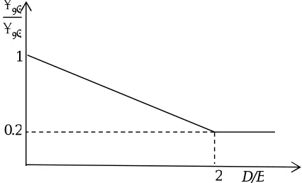
The critical buckling, Pcr, load in compression is given by the expression derived in the two-spring model (Koh and Kelly, 1987). Pcrdecreases with increasing lateral displacement. The area-reduction method considers the dependence of Pcr on lateral displacement and provides conservative results (e.g., Buckle et al., 2002; Warn et al., 2007). The reduced critical buckling load is given by
'cr cr( r / )
P P A A , where Ar is the reduced area of a bearing of diameter B due to lateral displacement
D. The area-reduction method suggests zero capacity for a bearing at a horizontal displacement equal to the diameter (or width) of bearing. However, experiments have shown that a bearing does not lose all its capacity but maintains a minimum capacity after the overlapping area reduces to zero (Warn et al., 2007). The model proposed by Warn et al. (2007) is considered here, which uses a bilinear approximation of the area-reduction method and takes into account the finite buckling capacity of a bearing at zero overlap area. The piecewise linear approximation of the area-reduction model is illustrated in Figure 2.
Figure 1. Stress softening under compression Figure 2. Piecewise linear model in compression
Load
= 1
1 + 3
Softening behavior
Deformation 2
′
1
0.2
Cavitation in Tension
Cavitation is followed by the substantial reduction in the vertical stiffness indicated by highly discernible transition on the tensile load-deformation curve. Gent (1990) suggested that cavitation occurs at a negative pressure of about 3G, and the cavitation force Fc is given by the expression 3GAo, where
o
A is the bonded rubber area and G is the shear modulus of rubber obtained experimentally from the testing of elastomeric bearings at large shear deformations under nominal axial loads.
Post-cavitation Behavior
Most of the available mathematical models use a very small arbitrary value of post-cavitation stiffness. Constantinou et al. (2007) suggested the following expression for post-cavitation stiffness:
post cavitation r EA K
T
(2)
where E is the elastic modulus of rubber. Following the formation of cracks in the rubber layer of elastomeric bearing after cavitation, rubber loses its triaxial state of stress and experiences uniaxial tensile stress. Hence, the elastic modulus used in Equation (2) is the Young’s modulus of rubber.
Experiments have shown that the post-cavitation stiffness of elastomeric bearings decreases with increasing tensile deformation. It is assumed here that area used in Equation (2) is the “true area” of bearing excluding the total area of cavities that change with tensile deformation. If the rubber area is considered to be made up of infinite number of small area elements, every time a cavity is formed, an area element is eroded. The greater the area, the greater the rate of destruction of area elements. So the rate of reduction of true area with respect to tensile deformation would be proportional to the instantaneous true area at any moment, which can be expressed mathematically as:
A kA u
(3)
where k is defined as cavitation parameter, which is constant for a particular elastomeric bearing and describes the post-cavitation variation of tensile stiffness and area. Equations (2) and (3) produce set of differential equations for post-cavitation behavior. These sets of differential equations are solved using initial conditions at the onset of cavitation
F uc, c, c, c,Ao
to obtain the current state
F u, , , , A
as:( c)
k u u o
AA e (4)
1
1 1 k u uc
c
r
F F e
kT
(5)
1
1
r c r c
kT kT
c
r
e e
kT
(6)
Strength Degradation in Cyclic Loading
Cavitation in elastomeric bearings is accompanied by the irreversible damage due to formation of micro cracks in the volume of rubber. When bearing is loaded beyond the point of cavitation and unloaded, it returns along a new path and cavitation strength is reduced. The area enclosed between loading and unloading amounts to the hysteretic energy due to damage in the bearing. Subsequent loading follows the latest unloading path elastically until strain exceeds the past maximum value umax, below which loading has the effect of only opening and closing of existing cavities within the rubber. Once loading exceeds the past maximum value of tensile strain, the formation of new cavities leads to increased damage, and follows the post cavitation behavior defined previously by Equation (5). Upon load reversal, it again traces back a new unloading path and cavitation strength is reduced. Unloading paths can be approximated with a straight lines between the point of maximum strain (Fmax,umax) to the point of reduced cavitation strength (Fcn,ucn). These points change with increasing number of cycles. To capture this behavior mathematically, a damage index is defined such that the updated cavitation strength as a function of initial cavitation strength is given by the expression:
(1 )
cn c
F F (7)
The damage index represents the cumulative damage in the bearing (01). It is a function of maximum deformation experienced by the bearing under tensile loading. Mathematically it can be expressed as f u( max)
, where
f satisfies the following relations: 1) ( )f uc 0 (No strength reduction up to cavitation deformation), and 2) f u( max)max(Damage index converges to a maximum value after large deformations). A function satisfying these properties is given by:max 1
c
c
u u a
u e
(8)
where a is the strength degradation parameter that defines the rate of damage and max is the maximum damage that can be expected in a bearing. The load-deformation behavior of elastomeric bearings under cyclic tensile loading is summarized in Figure 4.
Figure 3. Post-cavitation behavior Figure 4. Strength reduction under cyclic loading
Tensile force
Tensile deformation
= 1 + 1 1− ( )
Tensile force
Tensile deformation
( , )
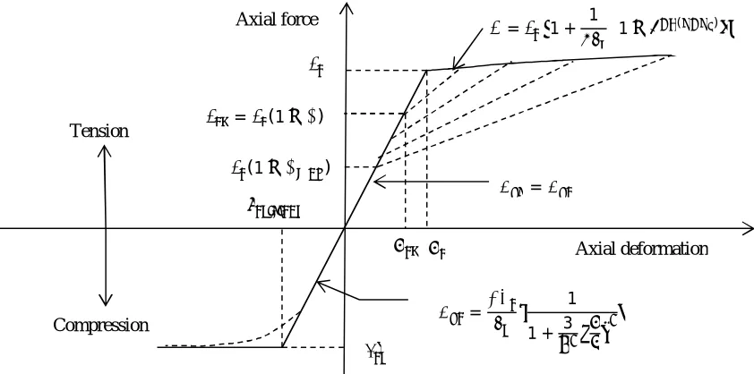
Mathematical Model in Axial Direction
A mathematical model of an elastomeric bearing in the axial direction is presented in Figure 5, which captures the following characteristics in the axial direction: 1) buckling in compression, 2) coupling of vertical and horizontal motion, 3) cavitation, 4) post-cavitation variation, and 5) strength degradation due to cyclic loading. The model uses three unknown parameters: 1) a cavitation parameter,
k, 2) a strength degradation parameter, a, and 3) a damage index, max.
Figure 5. Mathematical model of elastomeric bearings in axial direction
MECHNANICAL BEHAVIOR IN SHEAR
Coupled Horizontal Response
A smooth hysteretic model is used for elastomeric bearings in horizontal shear, which is shown in Figure 6. It is based on the model proposed by Park et al. (1986) and extended for the analysis of elastomeric bearings under bidirectional motion.
Figure 6. Mathematical model in shear Figure 7. Idealized behavior in shear
Axial force
Axial deformation (1− ∅ )
= (1− ∅)
= 1
1 + 3 = Tension
Compression
= 1 + 1 1− ( )
Force
Displacement
Force
Parameters have been expressed here in the form that is typical of seismic isolation design, namely, initial elastic stiffness Kel, characteristic strength Qd, yield strength FY, yield displacement Y , and post-elastic stiffness Kd. The isotropic formulation of the model in terms of restoring forces in orthogonal directions, Fx and Fy, is given by the equation (Mokha et al., 1993; Nagarajaiah et al., 1989):
x x x x
d d YL L
y y y y
F U U Z
c K A
F U U Z
(9)
where YLis the effective yield stress of confined rubber, ALis the cross-sectional area of lead-core, and
d
c is a parameter that accounts for the viscous energy dissipation in rubber. Zxand Zyrepresents the
hysteretic component of the restoring forces. Both have units of displacement and are function of time histories of uxand uy. The biaxial interaction is given by the following differential equation:
2
2
x x x x y y y
x x
y x y x x y y y y
Z Sign U Z Z Z Sign U Z
Z U
Y A I
Z Z Z Sign U Z Z Sign U Z U
(10)
Parameters and control the shape of the hysteresis loop and A is the amplitude of the restoring force.
Heating of lead-core
For LR bearings, the effective yield stress of lead used in Equation (9) is not constant but decreases with the number of cycles due to heating of the lead core under large cyclic displacements. The extent of reduction depends on the geometric properties of bearing and speed of motion. Kalpakidis et al.
(2010) proposed a dependency of the characteristic strength of LR bearings on instantaneous temperature of lead core, which itself is a function of time. The sets of equations proposed by Kalpakidis et al. (2010) is used here to describe heating of the lead core.
Equivalent damping
The damping in LR bearings is primarily contributed by the energy dissipation in the lead core and the contribution of viscous damping in the rubber is typically neglected. The force-displacement loop of an elastomeric bearing is idealized as in Figure 7, and the effective period and effective damping of the isolation system are calculated using following set of equations (AASHTO, 2010; ASCE, 2010):
2
1
2 ; ;
2
d
eff eff d eff
eff eff
Q
W EDC
T K K
K g D K D
(11)
2
4 2
1 2
d d
eff
eff d
Q D Y Q
K D K D
(12)
2
d eff d
Q K D (13)
The characteristic strength of LDR bearings can be estimated if the value of displacement D due to earthquake shaking is known from the simplified analysis (e.g., Constantinou et al., 2011).
Variation in shear modulus
The effective shear modulus of elastomeric bearings is obtained from experimental data. LDR and LR bearings show viscoelastic and hysteresis behavior in shear, respectively. The effective stiffness,
eff
K , at displacement amplitude D is calculated using expression Keff (|F | |F |) / (| | | |)
,
where and are the maximum and minimum horizontal displacements obtained from an experiment, and Fand Fare the corresponding forces. The effective shear modulus is determined using the expressionGeff K Teff r/Ar. Most of the available mathematical models use a constant shear modulus for
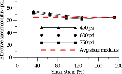
elastomeric bearing, although shear modulus varies with strain and axial loads. Increasing the axial pressure reduces the shear modulus. However, if the shear modulus, G, is determined from testing of elastomeric bearings at large strains and under nominal axial pressure, the value of G already includes some effects of axial load. Moreover, Constantinou et al. (2007) report that effect of axial load on shear stiffness is negligible. A typical variation of shear modulus with strain under different nominal axial pressures is shown in Figure 8 for a LDR bearing of diameter 35.5 inch (shape factor = 26).
0 40 80 120 160 200
Shear strain (%) 0
20 40 60 80
E
ff
e
ct
iv
e
sh
ea
r
m
o
d
u
lu
s
(p
si
)
450 psi
600 psi 750 psi
Avg shear modulus
Figure 8. Stress and strain dependency of LDR bearings (courtesy of DIS Inc.)
The shear modulus of natural rubber decreases with increasing strain up to 100%, remains relatively constant for shear strain between 100 and 200%, and increases again at shear strains of 200 to 250%. The shear modulus obtained from testing of elastomeric bearings at large strains is used for horizontal stiffness (LDR bearings), post-elastic stiffness (LR bearings), and buckling load calculations.
Mathematical model in shear
For numerical implementation, the model is represented as sum of two sub-models: 1) a viscoelastic model of rubber, and 2) an elasto-plastic model of lead. The contribution of the rubber to the total resisting force is given by the first two terms in Equation (9) and the third term represents the contribution of the lead core. The sum of all three terms is the restoring force in the LR bearing. For LR bearings, the characteristic strength, or the yield stress of the lead core, decreases with the number of cycles under large shear deformation. The yield stress of the lead core at the reference temperature (beginning of motion) is obtained experimentally as it depends on the degree of confinement of the lead core in the bearing. A suitable value of yield displacement of the lead core can be assumed, often between 0.05Tr to 0.1Tr. It should be noted that small variations in the yield displacement do not substantially affect the displacement response of an isolated structure. For LDR bearings the hysteretic term in Equation (9) is replaced by the yield strength of the LDR bearing obtained using the assumed value of effective damping of the system.
MECHANICAL BEHAVIOR IN ROTATION AND TORSION
The torsional and rotational behaviors of individual elastomeric bearings do not significantly affect the overall response of a seismically isolated structure. Hence, behavior in rotation and torsion are represented by linear elastic springs with stiffnesses given as Kr E Ir s/Tr and Kt GIt /Tr, respectively, where, Er is the rotation modulus of the bearing, Is is the moment of inertia about axis of rotation in the horizontal plane, and It is the moment of inertia about the vertical axis.
COMPARISON WITH THE EXPERIMENTAL DATA
The mathematical models of elastomeric bearing were implemented in the software program OpenSees (McKenna et al., 2006) as two new User Elements for LDR and LR bearings. The three-dimensional continuum geometry of elastomeric bearing was modeled as a 2-Node, 12 DOF discrete element. The two nodes are connected by six springs, which represent the material models in an axial, two shear, torsional and two rotational directions. Three sets of experimental data, as shown in Figure 9, were used to investigate the capability of the proposed mathematical model to simulate the behavior of elastomeric bearings under cyclic tensile loading. The cavitation parameter, k, and the damage index,
max
, were obtained by calibration of the mathematical model with the experimental data. The strength degradation parameter, a, was assumed to be unity.
0 20 40 60
Tensile strain (%) 0
40 80 120
T
e
n
si
le
fo
rc
e
(k
N
)
0 20 40 6 0 80 100 Tensile strain (%) 0
100 200 300 400
T
e
n
si
le
fo
rc
e
(k
N
)
0 40 80 120 160
Tensile strain (%) 0
20 40 60 80 100
T
en
si
le
fo
rc
e
(k
N
)
The details of the bearings and the values of parameters estimated by calibration against experimental data are presented in Table 1.
Table 1. Properties of the bearings used for experimental comparison
The behavior of elastomeric bearings under shear and compression is well established, and the comparison of numerical results with the experimental data is not presented here. Validation of the mathematical model used for the strength degradation of LR bearings due to heating in lead core under cyclic shear loading is presented in Kalpakidis et al. (2010).
SUMMARY AND CONCLUSIONS
Mathematical models of LDR and LR bearings that can be used for the analysis of base isolated structures under beyond design basis shaking are presented. These mathematical models extend the available robust formulation in shear and compression, and a new phenomenological model is proposed for behavior under tension. The phenomenological model uses three unknown parameters that can be determined experimentally.
Robust numerical formulations are obtained with the mathematical models. Numerical models are implemented in OpenSees as new user elements, and numerical results compare well with the experimental data for behavior in tension. A formal model validation will require that unknown parameters of the model be obtained from experiments. In most cases, the strength degradation parameter,
a, can be assumed to be unity, and the damage index, max, will range between 0.5 and 0.9. These two parameters are not expected to have significant effect on the tensile response of an elastomeric bearing. The cavitation parameter, k, should be determined experimentally, or can be estimated based on the experimental data available for bearings of a similar shape, size, compound, and fabrication.
ACKNOWLEDGEMENTS
This research project is supported by a grant to MCEER from the United States Nuclear Regulatory Commission and the Lawrence Berkeley National Laboratory. This financial support is gratefully acknowledged. The authors thank former graduate students Dr. Yannis Kalpakidis of Energo Engineering and Dr. Gordon Warn of Penn State University for providing test data on elastomeric bearings.
REFERENCES
AASHTO (2010). "Guide specifications for seismic isolation design." American Association of State Highway and Transportation Officials, Washington, D.C.
ASCE (2010). "Minimum design loads for buildings and other structures." Reston, Va., American Society of Civil Engineers
Constantinou et al. (2007) Iwabe et al. (2000) Warn (2006)
Diameter (mm) 250 500 164
Shape factor 9.8 33 10.2
Cavitation parameter 60 15 20
Damage index 0.75 0.75 0.9
Buckle, I., Nagarajaiah, S., and Ferrell, K. (2002). "Stability of elastomeric isolation bearings: Experimental study." Journal of Structural Engineering, 128(1), 3-11.
Constantinou, M., Kalpakidis, I., Filiatrault, A., and Lay, R. A. E. (2011). "LRFD-based analysis and design procedures for bridge bearings and seismic isolators." Report 11-0004, MCEER, Buffalo, NY.
Constantinou, M. C., Whittaker, A. S., Kalpakidis, Y., Fenz, D. M., and Warn, G. P. (2007). "Performance of Seismic Isolation Hardware Under Service and Seismic Loading." Report 07-0012, MCEER, Buffalo, New York, 472p.
Gent, A., and Lindley, P. (1959). "The compression of bonded rubber blocks." Proceedings of the Institution of Mechanical Engineers 173(1959), 111-122.
Gent, A. (1990). "Cavitation in rubber: a cautionary tale." Rubber Chemistry and Technology, 63, 49. Iwabe, N., Takayama, M., Kani, N., and Wada, A. (2000). "Experimental study on the effect of tension
for rubber bearings." Proceedings: 12th World Conference on Earthquake Engineering, New Zealand.
Kalpakidis, I. V., Constantinou, M. C., and Whittaker, A. S. (2010). "Modeling strength degradation in lead-rubber bearings under earthquake shaking." Earthquake Engineering and Structural Dynamics, 39(13), 1533-1549.
Koh, C. G., and Kelly, J. M. (1987). "Effects of axial load on elastomeric isolation bearings." Report No. 86/12, Earthquake Engineering Research Center, University of California, Berkeley, United States, 108p.
McKenna, F., Fenves, G., and Scott, M. (2006). Computer Program OpenSees: Open system for earthquake engineering simulation, Pacific Earthquake Engineering Center, University of California, Berkeley, CA., http://opensees.berkeley.edu.
Mokha, A. S., Constantinou, M. C., and Reinhorn, A. M. (1993). "Verification of friction model of teflon bearings under triaxial load." Journal of structural engineering New York, N.Y., 119(1), 240-261. Nagarajaiah, S., Reinhorn, A. M., and Constantinou, M. C. (1989). "Nonlinear Dynamic Analysis of
Three-Dimensional Base Isolated Structures (3D-BASIS)." Report NCEER-89-0019, National Center for Earthquake Engineering Research, University at Buffalo, United States, 132p.
Park, Y. J., Wen, Y. K., and Ang, A. H. S. (1986). "Random vibration of hysteretic systems under bi-directional ground motions." Earthquake Engineering & Structural Dynamics, 14(4), 543-557. Warn, G. P. (2006). "The coupled horizontal-vertical response of elastomeric and lead-rubber seismic
isolation bearings." PhD Dissertation, University at Buffalo.
Warn, G. P., Whittaker, A. S., and Constantinou, M. C. (2007). "Vertical stiffness of elastomeric and lead-rubber seismic isolation bearings." Journal of Structural Engineering, 133(9), 1227-1236. Yamamoto, S., Kikuchi, M., Ueda, M., and Aiken, I. D. (2009). "A mechanical model for elastomeric
seismic isolation bearings including the influence of axial load." Earthquake Engineering & Structural Dynamics, 38(2), 157-180.