ISSN(Online): 2320-9801
ISSN (Print): 2320-9798
I
nternational
J
ournal of
I
nnovative
R
esearch in
C
omputer
and
C
ommunication
E
ngineering
(An ISO 3297: 2007 Certified Organization)
Vol. 3, Issue 6, June 2015
CPW-Fed Capacitive Coupled Slot Antenna
Arpan Shah
1, Pooja Tendolkar
2, Nisha Sarwade
3M.Tech Student, Department of Electronics and Telecommunication Engineering, VJTI, Mumbai University, Mumbai, India1
M.Tech Student, Department of Electronics and Telecommunication Engineering, VJTI, Mumbai University, Mumbai, India2
Associate Professor, Department of Electronics and Telecommunication Engineering, VJTI, Mumbai University, Mumbai, India3
ABSTRACT:Coplanar waveguide (CPW) fed slot antennas are attractive due to low dispersion and ease of integration
with active and passive devices. In this paper, design of slot antenna fed by CPW through capacitive coupling with finite ground plane is presented. The propose antenna exhibit perfect impedance matching, unidirectional radiation patterns, and low cross polarization. Analysis of the effects of various slot dimensions on the parameters of the antenna design has been done. Proper simulated results are obtained by using a square slot of width 𝛌𝐠/𝟐fed by CPW through
capacitive coupling. The simulated results are obtained on Computer Simulation Technology (CST) Microwave Studio Software.
KEYWORDS: Coplanar waveguide,Microstrip antennas,Slot antennas, Conductor Backed, Capacitive Coupling.
I. INTRODUCTION
Slot antennas are currently under consideration for use in broadband communication systems due to their attractive features, such as wide frequency bandwidth, low profile, light weight, easy integration with monolithic microwave integrated circuit, low cost, and ease of fabrication [1]. These antennas have several advantages over common microstrip antennas as they provide good impedance matching, and bidirectional or unidirectional radiation pattern. Design of slot antenna using CPW feeding mechanism is done as it provides several advantages over microstrip line feed, such as low dispersion, low radiation leakage, ease of integration with active devices [2]-[3]. When the antenna is fed by microstrip line, misalignment can result because etching is required on both sides of the dielectric substrate. CPW feeding technique is used to excite the slot, since etching of the slot and the feeding line is one sided hence alignment error can be eliminated. In CPW the conductor formed a center strip separated by a narrow gap from two ground planes on either side.
The dimensions of the center strip, gap, thickness and the permittivity of the dielectric substrate determine the effective dielectric constant and the characteristic impedance of line [4]. Slot antenna results into wideband characteristic with CPW fed line having square slot [6] and CPW-fed hexagonal patch antennas [8] are demonstrated in the literature. In CPW-fed slot antenna by varying the dimensions of the slot and keeping it to the optimum value for wide bandwidth and proper impedance matching. In slot antenna geometries different tuning techniques has been carried out like circular slot [9], bow-tie slot [10], and wide rectangular slot [15].Various patch shapes such as hexagon, T, cross, forklike, and square are used to give wide bandwidth [6-12]. The dominant mode for the conductor backed CPW is quasi-TEM mode with zero cut off frequency. In [5], CPW fed rectangular slot antenna with ground plane is proposed.
ISSN(Online): 2320-9801
ISSN (Print): 2320-9798
I
nternational
J
ournal of
I
nnovative
R
esearch in
C
omputer
and
C
ommunication
E
ngineering
(An ISO 3297: 2007 Certified Organization)
Vol. 3, Issue 6, June 2015
this paper, CPW feeding technique using capacitivecoupling with finite ground plane is presented. CPW fed dual band antenna generates two frequency bands one is 827 MHz-833 MHz and the other is 895 MHz-902 MHz.GSM can operate in the same network with different frequency bands. Now a days as dual band antennas or multiple band antennas are in great demand for multiple frequency applications. Proposed antenna is simulated using CST Microwave Studio package by utilising transient solver technique. Simulated results are compared by varying the slot width from
𝜆𝑔/2 to 𝜆𝑔/4 in order to obtain the perfect impedance matching at frequency 900 MHz.The dimensions of the slot is
varied to obtain the optimum value of the slot so that the antenna resonates at frequency 900 MHz.
II. PROPOSED ANTENNA DESIGN MODEL
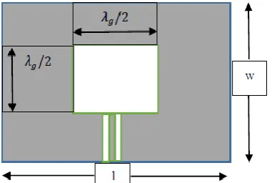
Fig. 1. illustrates the geometry of the proposed CPW fed capacitive coupled slot antenna with finite ground plane. The proposed antenna is formed by etching a half wavelength slot 𝜆𝑔/2 located symmetrically with respect to the
center of the CPW fed line,
λg=
c/f
εeff (1)
where𝜀𝑒𝑓𝑓 is the effective dielectric constant of CPW fed line and f is the resonant frequency. In the CPW, the effective
dielectric constant is independent of geometry and is equal to the average of dielectric constants of air and of the substrate.
εeff =
εair+εr
2 (2)
CPW fed capacitive coupled slot antenna is simulated using FR-4 loss free substrate with 𝜀𝑟= 4.3, height of the
substrate h= 1.59 mm and loss tangent 0.01 with finite ground plane of size l × w 280 mm × 300 mm. Length of the slot is equal to half wavelength 102 mm using equation (1) and the width of the slot is𝜆𝑔/2 . CPW feeding technique on
thin substrate.
0.5 ≤ W/h ≤ 2.0 (3)
S
S+2W≤ 0.4(4)
where S is the strip width and W is the gap width of a CPW fed line. Size of the strip width S and gap width W using equation (3) and (4) is 2 mm and 0.5 mm. Analysis of the antenna design parameters, reflection co-efficient, directivity, E-field pattern, H-field pattern are done by varying the width of the slot form 𝜆𝑔/2 to 𝜆𝑔/4. CPW is not very sensitive
to substrate thickness and allows a wide range of impedance value from 20 Ω to 250 Ω. The characteristic impedance of CPW fed line is nearly about 50 Ω.
ISSN(Online): 2320-9801
ISSN (Print): 2320-9798
I
nternational
J
ournal of
I
nnovative
R
esearch in
C
omputer
and
C
ommunication
E
ngineering
(An ISO 3297: 2007 Certified Organization)
Vol. 3, Issue 6, June 2015
TABLE I. Design parameters of the antenna
Parameters Description Optimal Value
L Length of the antenna 280 mm W Width of the antenna 300 mm l Length of the slot 102mm w Width of the slot 102 mm
Hence to overcome all drawbacks of cross-talk, dispersion, less gain and undesired radiation pattern is done by proposed design antenna model for desire frequency range using slot on the ground plane with Conductor Backed CPW feeding technique. The gap in the coplanar waveguide is usually very small and supports electric fields primarily concentrated in the dielectric. With little fringing field in the air space, the coplanar waveguide exhibits low dispersion. In order to concentrate the fields in the substrate area and to minimize radiation, the dielectric substrate thickness is usually set equal to about twice the gap width. In CPW a ground plane exists between any two adjacent lines, hence cross talk effects between adjacent lines are very week.
III.CONDUCTOR BACKED CPWANTENNA
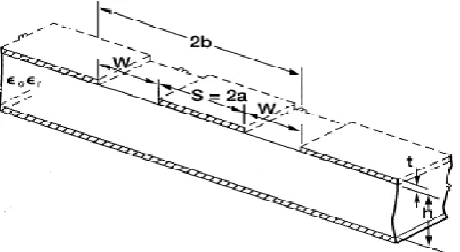
Using conductor backed CPW it has additional ground plane at the bottom surface of the substrate. It provides mechanical support to the substrate and also acts as a heat sink for active and passive circuit devices. In CPW the conductors formed a center strip separated by a narrow gap from two ground planes on either side. The dimensions of thecenter strip, the gap, the thickness and permittivity of the dielectric substrate determined the effective dielectric constant, characteristic impedance and the attenuation of the line as shown in Fig. 2. In CPW, the substrate thickness plays a less important role due to the fact that the fields are concentrated in the slots. The dominant mode for the conductor backed CPW is Quasi-TEM mode with zero cut-off frequency.
Fig. 2. Schematic of conductor Backed Co-planar Waveguide
CPW has ODD mode also called as Co-planar mode where the fields in the two slots are 180 out of phase and an EVEN mode known as coupled slotline mode where the fieldsare in-phase. Since the number of the electric and magnetic field lines in the air is higher than the number of the same lines in the microstrip case, the effective dielectric constant 𝜀𝑒𝑓𝑓 of CPW is typically 15% lower than the 𝜀𝑒𝑓𝑓 for microstrip, so the maximum reachable characteristic
ISSN(Online): 2320-9801
ISSN (Print): 2320-9798
I
nternational
J
ournal of
I
nnovative
R
esearch in
C
omputer
and
C
ommunication
E
ngineering
(An ISO 3297: 2007 Certified Organization)
Vol. 3, Issue 6, June 2015
IV.SIMULATION RESULTS
CST is used to simulate the proposed CPW fed slot antenna through capacitive coupling with finite ground plane. Fig.3shows the return loss of the proposed wide slot antenna, of width 𝜆𝑔/2 perfectly resonates at frequency 900 MHz
with dual band characteristics. By varying the slot width to 𝜆𝑔/4 results into a shift in resonant frequency, from 900
MHz to 856 MHz.Return loss is 𝑆11= -15 dB at 900 MHz frequency for the wide slot antenna, width of 𝜆𝑔/2.
Fig. 3. Simulated results of the reflection co-efficient of wide slot antenna of width𝜆𝑔/2.
Fig. 4VSWR nearly equal to 1.3 shows that good impedance matching is observed for the wide slot antenna of width
𝜆𝑔/2 at 900 MHz frequency
Fig. 4. VSWR of the proposed slot antenna fed by CPW
ISSN(Online): 2320-9801
ISSN (Print): 2320-9798
I
nternational
J
ournal of
I
nnovative
R
esearch in
C
omputer
and
C
ommunication
E
ngineering
(An ISO 3297: 2007 Certified Organization)
Vol. 3, Issue 6, June 2015
Fig. 5. Simulated radiation pattern of proposed antenna of E-plane.
Current density of the CPW fed capacitive coupled wide slot antenna with finite ground plane at 900 MHz as shown in Fig. 6.
Fig. 6. Current distribution of CPW fed antenna at frequency 900 MHz.
V. CONCLUSION AND FUTURE WORK
CPW fed capacitive coupled slot antenna with finite ground plane is proposed. Good impedance matching is accomplished with capacitive coupled slot antenna at frequency 900 MHz with dual band characteristics. Proposed antenna exhibit low dispersion by using CPW feeding mechanism, unidirectional radiation patterns and low cross polarization. Simulated results illustrate that proposed antenna has better –10 dB return loss at resonant frequency 900 MHz for wide slot, width of dimension 𝜆𝑔/2. Based on these characteristics wide slot capacitive coupled antennas fed
by CPW with finite ground plane is suitable in aircraft navigation systems and for communication applications.
ACKNOWLEDGEMENT
The authors would like to thank Prof. DrNishaSarwadefrom VJTI Mumbai, for her encouragement and inspiration to work on this current research topic.
REFERENCES
ISSN(Online): 2320-9801
ISSN (Print): 2320-9798
I
nternational
J
ournal of
I
nnovative
R
esearch in
C
omputer
and
C
ommunication
E
ngineering
(An ISO 3297: 2007 Certified Organization)
Vol. 3, Issue 6, June 2015
2. J.-W. Nia and S.-S. Hong, “A broadband CPW-fed bow-tie slot antenna,” in Proc. IEEE Antennas and Propagation Soc. Int. Sump, vol. 4, pp. 4483–4486, Jun.20–25, 2004.
3. A. A. Drawstring, A. Imani, “Printed wide-slot antenna for wide band applications,” IEEE Trans. Antennas Proper., vol. 56, no. 10, pp. 3097–3102, Oct. 2008.
4. K. P. Ray and Y. Rang, “Ultra wideband printed elliptical monopole antennas,” IEEE Trans. Antennas Proper., vol. 55, no. 4, pp. 1189– 1192, 2007.
5. R. Chair, A. A. Kick, and K. F. Lee, “Ultra wideband coplanar waveguide-fed rectangular slot antenna,” IEEE Antennas Wireless Propag.Lett., vol. 3, pp. 227–229, 2004.
6. B. K. Kormanyos, W. Harokopus, L. Katehi, and G. Rebeiz, “CPW-fed active slot antennas,” IEEE Trans. Microwave Theory Tech., vol. 42, pp. 541–545, Apr. 1994.
7. J.-Y. Sze, C.-I. G. Hsu, and S.-C. Hsu, “Design of a compact dual-band annular-ring slot antenna,” IEEE Antennas Wireless Propag. Lett., vol.6, pp. 423–426, 2007.
8. H. L. Lee, H. J. Lee, J. G. Yook, and H. K. Park, “Broadband planar antenna having round corner rectangular wide slot,” in Proc. IEEE Antennas and Propagation Society Int. Symp., vol. 2, pp. 460–463, Jun. 16–21, 2002.
9. A. U. Bhobe, C. L. Holloway, and M. Piket-May, “CPW fed wide-band hybrid slot antenna,” in Proc. IEEE Antennas Propag. Soc. Int. Symp. Dig, vol. 2, pp. 636–639, Jul. 2000.
10. H.-D. Chen, “Broadband CPW-fed square slot antennas with a widened tuning stub,” IEEE Trans. Antennas Propag., vol. 51, no. 4, pp. 1982–1986, Aug. 2003.
11. B. K. Kormanyos, W. Harokopus, L. Katehi, and G. Rebeiz, “CPW-fed active slot antennas,” IEEE Trans. Microwave Theory Tech., vol. 42, pp. 541–545, Apr. 1994.
BIOGRAPHY
Arpan Shah is Master of Technology inElectronics and Telecommunication Engineering, from VeermataJijabai
Technological Institute. Had an experience of two years in teaching profession. Area of interest is High power microwave devices and Antenna design.
PoojaTendolkaris pursuing Master of Technology in Electronics and Telecommunication Engineering, from
VeermataJijabai Technological Institute. She had an experience of two years in Teaching Profession. Area of interest is Microwave and Antenna design devices.
Dr NishaSarwade is Associate Professor in Electronics and Telecommunication Engineering Department at