Study of Seismic Analysis of Water Tank at
Ground Level
Abhijeet Babar
1, Dr. H. S. Jadhav
2P.G. Student, Department of Civil Engineering, Rajarambapu Institute of Technology, Islampur. Maharashtra, India1
Professor, Department of Civil Engineering, Rajarambapu Institute of Technology, Islampur. Maharashtra, India2
ABSTRACT: Liquid tank and especially the tanks are structures of high importance which are considered as the main
lifeline elements that should be capable of keeping the expected performance that is operation during and after earthquakes.Thus, researchers, in recent years, have focused on studying the seismic behaviour analysis and design of water tank.The paper consists of study of guidelines for seismic analysis of water tank at ground level.In this paper, Hydrodynamic forces exerted by the liquid on the wall of water tank and base slab will be considered in the analysis. These hydrodynamic forces will be evaluated with the help of spring mass model of water tanks. And also comparison of various parameters like seismic coefficient and hydrodynamic pressure of circular tank for various capacity and different heights of water level and water tank will be done by calculating seismic weight of tank and horizontal & vertical acceleration coefficient
.
KEYWORDS: seismic behaviour,Hydrodynamic forces, spring mass model, seismic coefficient, etc.
I.INTRODUCTION
II.RELATEDWORK
Much of a literature has presented in the form of technical papers till date on the dynamic analysis of Elevated Water Tanks. Different issues and the points are covered in that analysis i.e. dynamic response to ground motion, sloshing effect on tank, dynamic response of framed staging etc. Some of those are analyzed below.
1. George W. Housner (1963) had studied about the relation between the motion of water in the tank with respect
to tank and motion of whole structure with respect to ground. He has considered three basic conditions for this analysis. He studied that if water tank is fully filled i.e. without free board then the sloshing effect of water is neglected, if the tank is empty then no sloshing as water is absent. In above two cases water tower will behave as one-mass structure. But in case if there is free board, the water tower will behave as two-mass structure. Finally, he concluded that the tank fully filled is compared with the partially filled tank then it is seen that the maximum force to which the half-full tank is subjected may be significantly less than half the force to which the full tank is subjected. The actual forces may be as little as 1/3 of the forces anticipated on the basic of a completely full tank.
2. Sudhir K. Jain & Sameer U. S. (1991) Revised the IS code provision for seismic design of elevated water tanks. It is seen that, due to absence of a suitable value of performance factor for tanks, the code provision for rather low seismic design force for these structure. Simple expressions are derived, which allow calculations of staging stiffness, and hence the time period, while incorporating beam flexibility. The code must include an appropriate value of performance factor, say 3.0 for calculation of seismic design force for water tanks. An earthquake design criterion is incomplete, unless clear specifications are include on how to calculate the time period. A method for calculating the staging stiffness including beam flexibility and without having to resort to finite element type analysis has been presented. This method is based on well-known portal method which has been suitably developed to incorporate the beam flexibility and the three dimensional behaviour of the staging. 3. O. R. Jaiswal (2008)had done experimental and numerical study to obtain the sloshing frequency of liquid contained in tanks of different shapes and tanks with internal obstructions.The experimental study is done on laboratory models of tanks, which are excited using an Electro-Magnetic Shake Table. The numerical study is done with the help of finite element model of tank-fluid system using ANSYS software. A comparison of experimental and numerical results is carried out
.
4.
Gaikwad M. V. &Prof.Mangulkar M. N. (2013) had detail study and analysis it was found that, for same capacity, same geometry, same height, with same staging system, with same Importance factor & Response reduction factor, in the same Zone; response by equivalent static method to dynamic method differ considerably. Even if we consider two cases for same capacity of tank, change in geometric features of a container can shows the considerable change in the response of tank. As the capacity increases, difference between the response increases. Increase in the capacity shows that difference between static and dynamic response is in increasing order. It is also found that, for small capacity of tank the impulsive pressure is always greater than the convective pressure, but it is vice- versa for tanks with large capacity. Magnitude of both the pressure is different.
III.THE METHODOLOGY
The theoretical formulae’s and methodology used for the analysis of water tank at ground level. These theoretical formulae’s and methodology used for the analysis are based on the “IITK-GSDMA Guidelines on Seismic Design of
Liquid Storage Tanks” (Provisions with commentary) given by Sudhir K. Jain and O R Jaiswal, in October 2007. When earthquake occurs water inside the tank is in motion due ground motion. Due to this ground motion
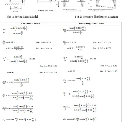
wall and the tank base in addition to the hydrostatic pressure.Thus in order to include the effect of hydrodynamic pressure in the analysis, the tank is idealized as an equivalent spring mass model as stated by Housner, which includes the effect of tank wall – liquid interaction. The parameters of this model depend on geometry of the tank and its flexibility. The approach followed for the analysis of different water tank problems is same, only the formulation and parameters used in each case vary according to the Geometry and support conditions
Fig 1: Spring Mass Model Fig 2: Pressure distribution diagram
In this number of problems of various capacities ranging from 400 m3 to 1200 m3 for circular tank by keeping its diameter constant by varying its height. By using IITK-GSDMA guideline solve the different problem and find out the different parameters as shown below:
Table 2: Problems having different capacity Table 3: Parameters of Spring –Mass Model
Table 4: Seismic Parameters Capa
city (cub. m)
mi (kg)
mc (kg)
hi (m)
hc (m)
hi* (m)
hc* (m)
400 135492 248015 1.33 1.93 4.78 4.43
600 294000 288000 1.99 3.08 4.74 4.46
800 491021 303097 2.67 4.5 4.90 5.3
1000 702681 309470 3.31 5.99 5.19 6.42
1200 924000 311228 4.24 7.64 5.58 7.85
Capacity (cub.m)
Diameter (m)
Height of
tank up to Free board (m)
400 12 3.54
600 12 5.31
800 12 7.1
1000 12 8.84
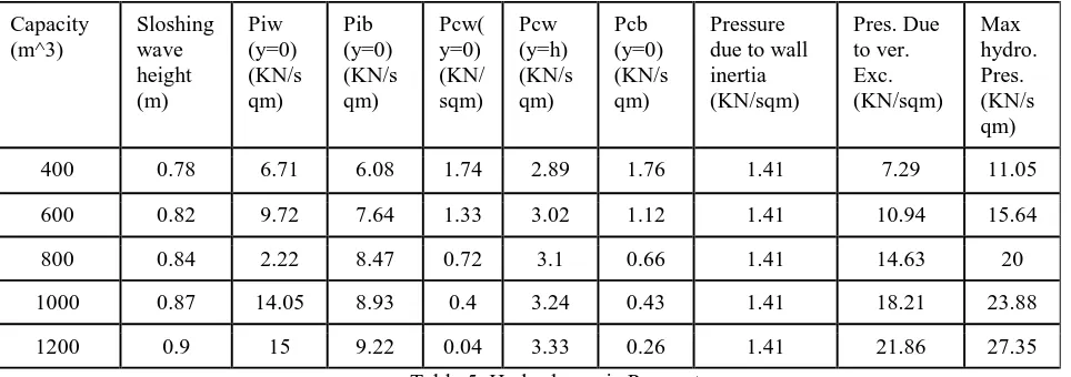
Table 5: Hydrodynamic Parameters
IV.RESULTS
The following results are obtained by solving the different problem and compare water tank at ground level for various parameters like base shear hydrodynamic pressure impulsive and convective mass, bending moment at base, sloshing wave height for same and different capacity.
h/D (m)
0.29 0.4 0.59 0.74 0.88
mi/m 0.34 0.49 0.61 0.70 0.77
mc/m 0.62 0.48 0.38 0.3 0.2
Variation of Variation of Convective
mi/m & mc/m Vs h/D ratio Time period(Tc) Vs h/D ratio
0 0.2 0.4 0.6 0.8 1
0.29 0.4 0.59 0.74 0.88
mi/m mc/m 3 3.5 4 4.5
0.29 0.4 0.59 0.74 0.88
Tc(sec) Capacity (m^3) Sloshing wave height (m) Piw (y=0) (KN/s qm) Pib (y=0) (KN/s qm) Pcw( y=0) (KN/ sqm) Pcw (y=h) (KN/s qm) Pcb (y=0) (KN/s qm) Pressure due to wall inertia (KN/sqm) Pres. Due to ver. Exc. (KN/sqm) Max hydro. Pres. (KN/s qm)
400 0.78 6.71 6.08 1.74 2.89 1.76 1.41 7.29 11.05
600 0.82 9.72 7.64 1.33 3.02 1.12 1.41 10.94 15.64
800 0.84 2.22 8.47 0.72 3.1 0.66 1.41 14.63 20
1000 0.87 14.05 8.93 0.4 3.24 0.43 1.41 18.21 23.88
1200 0.9 15 9.22 0.04 3.33 0.26 1.41 21.86 27.35
h/D (m)
0.29 0.4 0.59 0.74 0.88
Tc (sec.)
4.2 3.87 3.76 3.59 3.53
h/D (m)
0.29 0.4 0.59 0.74 0.88
Base Shear (KN)
542 955 1509 2069 2651
h/D (m)
0.29 0.4 0.59 0.74 0.88
Ti (sec.)
Variation of impulse Variation of Time period(Ti) Vs h/D ratio Base Shear Vs h/D ratio
Variation of Variation of
Bending Moment Vs h/D ratio: Overturning Moment Vs h/D ratio
0 0.01 0.02 0.03 0.04 0.05 0.06 0.07
0.29 0.4 0.590.740.88 Ti(sec)
0 500 1000 1500 2000 2500 3000
0.29 0.4 0.59 0.74 0.88 Base shear(KN)
h/D(m) 0.29 0.4 0.59 0.74 0.88
Moment at bottom of wall (KN-m)
894 2206 4554 7620 12111
h/D (m)
0.29 0.4 0.59 0.74 0.88
Overturning Moment (KN-m)
2238 4435 7651 1146
3
1606 7
h/D(m) 0.29 0.4 0.59 0.74 0.88
Max.
Hydrodynamic pressure (KN/m2)
11.05 12.64 20 23.88 27.35
Capacity(m3) 400 600 800 1000 1200
Sloshing Wave height(m)
0.78 0.82 0.84 0.87 0.9
0 5000 10000 15000 20000
0.29 0.4 0.59 0.74 0.88
Overturning Moment (KN-m)
0 2000 4000 6000 8000 10000 12000 14000
0.29 0.4 0.59 0.74 0.88
Variation of Max.Hydrodynamic pressureVs h/D ratio Sloshing wave height VsCapacity
V.CONCLUSION
For circular water tank with same storage capacity and different height, the Base shear, Bending Moment & Max. Hydrodynamic pressure gradually increases with increase in h/D ratio.
For circular water tank with same storage capacity but different height of tank wall, in such case sloshing wave height increases up to certain limit & after that it gradually decreases.
The increase in the ratio of maximum depth of water to the diameter of tank i.e. (h/D) will lead to increase in impulsive mass participation factor and decrease in convective mass participation factor. The graph also illustrates that the sum of mass participation factor (impulsive & convective) exhibit the unit value all along the horizontal axis. For circular water tank the h/D ratio 0.4, the mass participation factor for impulsive & convective are nearly equal.
REFERENCES
[1] Chen W, Haroun MA, Liu F (1996). “Large amplitude liquid sloshing in seismically excited tanks”. Earthquake Engineering and Structural Dynamics 25: 653–69.
[2] Dr. SuchitaHirde, Ms. AsmitaBajare, Dr. ManojHedaoo (2011). s“Seismic Performance Of Elevated Water Tanks” International Journal of Advanced Engineering Research and Studies E-ISSN2249 – 8974.
[3] George W. Housner, (1963) “The Dynamic Behaviour of Water Tank” Bulletin of the Seismological Society of America. Vol. 53, No. 2, pp. 381-387.
[4] Gaikwad MadhukarV.&Prof. MangulkarMadhuri N. (2013) “Seismic Performance of Circular Elevated Water Tank with Framed Staging System” International Journal of Advanced Research in Engineering and Technology (IJARET) Volume 4, Issue 4, May – June 2013, pp. 159-167.
[5] I.S 1893-2002 “Criteria for Earthquake Resistant Design of Structures.
[6] Jaiswal O. R and Sudhir K Jain (November 2005), “Modified proposed provisions for aseismic design of liquid storage tanks: Part II – commentary and examples”, Journal of Structural Engineering Vol. 32, No.4.
[7] Jaiswal, O.R., Kulkarni, S., Pathak, P. (2008), “A Study on Sloshing Frequencies of Fluid-Tank System”, in Proceedings of 14th World Conference on Earthquake Engineering, Beijing, China.
[8] Sudhir K. Jain, Sameer U.S., 1990, “Seismic Design of Frame Staging for Elevated Water Tank” Ninth Symposium on Earthquake Engineering (9SEE-90), Roorkey, December 14-16, Vol-1.
[9] Sudhir K. Jain and Medhekar M. S. October-1993, “Proposed provisions for aseismic design of liquid storage tanks” Journals of structural engineering Vol.-20, No.-03.
[10] Sudhir K. Jain &Jaiswal O. R. September-2005, Journal of Structural Engineering Vol-32, No 03.
0 5 10 15 20 25 30
0.29 0.4 0.59 0.74 0.88
Max. Hydrodynamic pressure (KN/m2)
0.7 0.75 0.8 0.85 0.9 0.95
400 600 800 1000 1200