Optimization of Material to Improve Heat
Transfer in Air Cooled Condenser by Using
CFD Analysis
R.Phani krishna 1, V.Ravi kumar 2
P.G. Student, Department of Mechanical Engineering, ASRCE, Tanuku, JNTUK, Andhra Pradesh, India1
Assistant Professor, Department of Mechanical Engineering, ASRCE, Tanuku, JNTUK, Andhra Pradesh, India2
ABSTRACT: The performance of a cross-flow, micro-channel condenser of a vapour compression refrigeration system subjected to the maldistribution of air flow has been studied analytically.
The performance of condenser is studied analytically by changing fins materials when using R22 and R407c. Especially, the material with high thermal conductivity is used as fins material. In this thesis like copper alunminium and brass are chosen to analyse the performance of fin materials on condenser efficiency.
To evaluate heat transfer rate and heat transfer coefficient for the fluids R-22 and R407c with different fins materials ANSYS software is used. Thermal analysis is to determine the temperature distribution and heat flux for all three materials. 3D modelling is done by Creo-parametric.
By comparing results of aluminium and brass with copper fins of condenser, it is observed that using copper as a fin material for high cooling capacity and COP of the condenser when using refrigerant R407c. In steady state thermal analysis thermal error and total heat flux for copper having the significant variation i.e., thermal error = 0.0074696 and total heat flux = 22752 W/m2. While considering fluent analysis for R22 and R407c it is absorbed that contours of enthalpy and contours of static temperature for R407c is giving better results i.e., contours of enthalpy 4200 J/kg and contours of static temperature 309 k
I.INTRODUCTION
II. LITERATURE REVIEW
REVIEWS ON RECENT MATERIALS OF COOLING FINS OF CONDENSER:
The majority of the research work focused condenser fins efficiency. But in this thesis discusses the single air-cooled. The refrigerant used in this heat exchanger is R22. Compare the analytical results value of existing system with new modified system. Here using different materials like Copper Aluminium and brass as condenser fin materials and analysis is done at constant air flow.
INVESTIGATION ON CONDENSER FINS:
Jameel and Syed (1999) have developed a thermodynamic model to simulate the working of actual refrigeration system. Simple cycle used for the analysis showed that the super heating has more influence on the COP of the system. Using this model, the COP and other system parameters were calculated with ± 2% accuracy.Liang and Wong (2001) conducted experiments and developed a model to exploit the possibility of applying the equilibrium two-phase drift flux model to simulate the flow of refrigerant R134a in the capillary tube expansion device. The details of flow characteristics of R134a in a capillary tube, such as distribution of pressure, void fraction, dryness fraction, phase’s velocities and their drift velocity relative to the center of the mass of the mixture are presented.Corberan et al (2004) predicted a model to calculate the mass flow rate of refrigerant in a capillary tube by means of the conservation equations (mass, momentum and energy) over individual control volumes and included in IMST-ART, software for simulation and design of refrigeration equipment. The addition of capillary tube model allows calculating the superheat at the evaporator giving the capillary tube geometry. A simulation with different operative conditions and capillary geometry is done and the results are compared for R22 with those given by ASHRAE correlations.Li et al (2004) presented a general model format for Adjustable Throat Area Expansion Valves (ATAEV), including TEV and EEV that utilizes manufacturer’s rating data. Model structures for three types of valve geometries are derived. The model format for ATAEV was vali dated by using manufacturer performance rating data and the flow through the adjustablearea expansion device is not chocked. Two model formats and parameter estimation procedures were considered and their predictions were compared with laboratory measurements. The non linear modeling approach only requires data at a rating condition to obtain parameters and gave good predictions over a wide range of operating conditions when compared with laboratory data.
Sarntichartsak et al (2007) conducted experiments on inverter air conditioner with variation of capillary tube using R22 and R407C and predicted model. The two zone model, the distributed model and combined model were compared to estimate the optimal charge inventory. The model prediction agrees with the experimental data in the range of 40 -50 HZ.Beghi et al (2009) reported some results of a research project aimed at deriving simple, high-performance, adaptive and robust control algorithms for EEV to control dry expansion evaporators superheat temperature. The adaptation scheme is based on the on-line identification of simplified, first order plus dead time (FODPT) model of the process. The Zhaung-Atherton method is then used to derive a new set of Proportional Integral-Derivatives (PID) parameters, which allow the system to improve the closed-loop performance. The control algorithm has been evaluated by restoring to a detailed, a particular virtual prototyping software environment. The algorithm exhibits better performance than other auto tuning approaches, such as the one based on relay feedback. The performance has been evaluated by resorting to standard indexes such as Integral Squared Error (ISE) and Integral Squared Time Weighted Error (ISTE).S.S. Hu and B.J. Huang investigated of a high-efficiency split residential water cooled air conditioner that utilizes cellulose pad as the filling material of the cooling tower. The cooling tower performance is improved due to good water wet ability of the cellulose pad that causes a uniform water film over the entire surface of the pads and a perfect contact between water and cooling air. The cooling tower is integrated with the condensing unit of the Rankine cycle in structure design to form a vintegral-type outdoor unit.
DESIGN CALCULATIONS OF CONDENSER: Dimensions of the condenser tube made up of copper: 1. Diameter of tube =10mm
4. Pitch value = 15mm 5. No. of turns =11 Dimensions of fins:
1. Height of the fin = 300mm 2. Thickness of the fin = 1mm 3. Width= 50mm 4. No. of fins =10
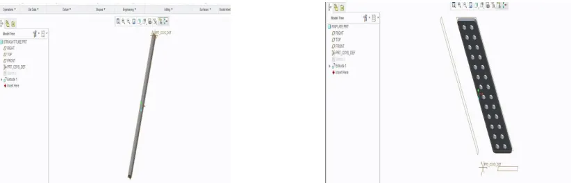
Condenser tube is designed into two parts later it assembled in pro-e assembling software. Part design and assembled part is indicated below
Fig 3.1: Image represents condenser tube of dia 10mm condenser fin plate of 1 mm thickness and 300 mm length.
ANALYSIS OF FIN:
thermal error of Al fin in steady state thermal analysis heat flux of brass fin in steady state thermal analysis
heat flux of copper fin in steady state thermal analysis heat flux of copper fin in steady state thermal analysis
ANALYSIS OF CONDENSER
:
static temp. vs position in condenser with Al fins using R22 static temp. in condenser with Al fins while using R407c
static temp. vs position in condenser with Al fins using R407c static temp in condenser with copper fins using R22
static temp. in condenser with copper fins while R407c temp vs position in condenser with copper fins using R407c
III. RESULTS
1.1. Results of Steady state thermal analysis
In this table temperature and heat flux of the material copper is low when compared to and brass. Hence it shows copper is better material when compare to aluminum and brass
Material Directional heat flux
W/m2
Thermal error Temperature oC Total heat flux W/m2
Aluminium 22806 0.0029102 60 22925
Copper 22632 0.0074696 60 22752
Brass 22810 0.002814 60 22929
Table: 4.1. Table indicating directional heat flux, thermal error, temperature and total heat flux of the materials, copper and brass.
1.2. Results of fluent analysis for R22
this table contours of enthalpy “j/kg” and Contours of static temperature “k” of copper with R22 is far better then and brass. Hence it shows copper is better material when compare to aluminum and brass.
R22
Contours of enthalpy j/kg Contours of static temperature k Aluminium 1790 318
Copper 1480 312
Brass 1160 315
1.3. Results of fluent analysis for R407c
R407c
Contours of enthalpy j/kg Contours of static temperature k Aluminium 3350 326
Copper 4200 309
Brass 3600 325
Table: 4.3. Table indicating Contours of enthalpy j/kg and Contours of static temperature k of the materials , copper and brass when using R407c
1.4. Graphical representation:
static temp. vs position in condenser with Al fins using R22 static temp. vs position in condenser with Al fins using R407c
static temp vs position in condenser with brass fins using R22 static temp vs position in condenser with brass fins usingR407c
IV. CONCLUSION
In this paper I have designed an air conditioner condenser. Present used material for fin is aluminium alloy and cooling fluid is HCFC. I have modeled the condenser in 3D modeling software pro-engineering.To optimize the condenser for best result, thermal analysis is done on the condenser. Analysis is done using fin materials like aluminium, copper and brass because of high thermal conductivity. In earlier studies, use of alternative refrigerants plays an important role in forming problems such as global warming and ozone depletion. It is observed that R407c has zero ODP, considerably GWP, low flammable, eco-friendly refrigerant and also observed nearly the same flow characteristics of R22 observed in this thesis.
By observing the thermal analysis results, by using fin material copper thermal flux is more then by using other two materials.Comparing R22 and 407c, R22 has high temperature at 6th turn of coil after 6th turn it gaining energy from surroundings reaches same temperature at the end.For R407c it happens at 11th turn of the coil, So, R407c is better to use with 11 turns for effective condensation. So I conclude that using condenser with fin thickness of 1mm and fin material copper gives better results.
REFERENCES
[1]Experimental Investigation of Split air Conditioning System by liquid Based Cooling System by Balaji N, Suresh Mohan kumar pefficient usage of waste heat from air conditioner by M. Joseph
[2]Stalin, S. Mathana Krishnan, G. Vinoth Kumar Comparitive analysis of an automotive air conditioning systems operating with CO2 and R134a by J. Steven Brown a, Samuel F. Yana-Motta b,Piotr A. Domanski c Performance Enhancement of Air-cooled Condensers by M. M. Awad , H. M. Mostafa , G. I. Sultan , A. Elbooz
[3]S.H. Noie-Baghban, G.R. Majideian, “Waste heat recovery using heat pipe heat Exchanger (HPHE) for surgery rooms in hospitals”, Applied Thermal Engineering, Vol. 20, (2000) 1271-1282.
[4]P.Sathiamurthi, R.Sudhakaran “Effective utilization of waste heat in air conditioning. Proc. (2003) 13-14.
[5]P. Sathiamurthi, PSS.Srinivasan, design and development of waste heat recovery system for air conditioner, European Journal of Scientific Research ISSN 1450-216X Vol.54 No.1 (2011), Pp.102- 110.
[6]N.Balaji, P.Suresh Mohan Kumar, Eco friendly Energy Conservative Single window Air Conditioning System by Liquid Cooling with helical inter cooler ISSN 1450-216X Vol.76 No.3 (2012), pp.455-462.
[7]S.C.Kaushik, M.Singh. “Feasibility and Refrigeration system with a Canopus heat exchanger”, Heat Recovery Systems & CHP, Vol.15 (1995)665 - 673.
[8]R.TugrulOgulata, “Utilization of waste-heat recovery in textile drying”, Applied Energy.
[9]A mathematical model of a steam condenser in off-design operation by Rafał Marcin Laskowski, Journal of Power Technologies 92 (2) (2012)