PLC Based Automated Solar Tracking using
Android app
A. Maideen Abdhulkader Jeylani1, A.Mahaboob Subahani2, K.Manimegalai3, A.Priyadharshini4
Assistant Professor, Department of EEE, Sri Krishna College of Engineering and Technology, Coimbatore, India1
Assistant Professor, Department of EEE, PSG College of Technology, Coimbatore, India2
U.G. Student, Department of EEE, Sri Krishna College of Engineering and Technology, Coimbatore, India3
U.G. Student, Department of EEE, Sri Krishna College of Engineering and Technology, Coimbatore, India4
ABSTRACT: The solar PV is an exciting technology but suffers from low efficiency due to inaccurate tracking
systems. This paper focuses on a scheme for a renewable energy source based Intelligent Solar panel gesture system by sun track, to turn the panel to focus the sun in day time and to focus to the street lighting at night time, this system which offers considerable advantages over the existing solar panel motion systems. This whole system is controlled and monitored by the PLC and it can be accessed by Android Application anywhere through Internet and WLAN. Stepper motor driver circuits can also be controlled by a microcontroller. The system offers good energy efficiency, reduced greenhouse effect and a versatile control options. The analysis shows that the system is cost effective and Return of Investment (ROI) is comparatively high.
KEYWORDS:solar PV , PLC, WLAN , Stepper motor, greenhouse effect, Return of Investment (ROI)
I.
I
NTRODUCTION
The increasing demand for electricity necessitates the development of methods to improve the efficiency of power generation units that utilize renewal resources. The sun is one such highly reliable source of electrical energy. The output of the solar panels directly depends on the amount of light they gather which in turn is influenced by the position of the panel with respect to the sun. If a fixed panel with flat surface is used, the light waves from the sun are almost parallel to the surface of the panel in the morning and evening. Hence, the power produced by the panel at those times is nearly zero [3]. As the day progresses, there is a steady increase in power until a point at which the light incident on the panel is perpendicular to the panel surface.
Fig.1.Schematic representation for solar tracking
There are 2 types of trackers, namely, single axis tracker and dual axis tracker. Figure 1,2,3 shows that single axis trackers have one degree of freedom that acts as an axis of rotation. Dual axis trackers have two degrees of freedom that act as axes of rotation. Dual axis trackers allow for optimum solar energy levels due to their ability to follow the sun vertically and horizontally.
Fig. 2. Tilted one axis Tracking systems
II.FLOWCHART
The following is a simple flow chart representing the functioning of the system. Solar power tower convert sunshine into clean electricity. The technology uses many large, sun-tracking mirrors commonly referred to as heliostats to focus sunlight on a receiver at the top of a tower. A heat transfer fluid heated in the receiver is used to generate steam, which, in turn, is used in a conventional turbine-generator to produce electricity. Early power towers such as the Solar One plant uses steam as the heat transfer fluid. Current power towers such as Solar Two use molten nitrate salt. Nitrate salt is used because of its superior heat transfer and energy storage capabilities. A heat transfer fluid heated in the receiver is used to generate steam, which, in turn, is used in a conventional turbine-generator to produce electricity. Early power towers such as the Solar One plant uses steam as the heat transfer fluid. Current power towers such as Solar Two use molten nitrate salt. Nitrate salt is used because of its superior heat transfer and energy storage capabilities.
III. SIMULATIONANDRESULTS
The sun tracking system is designed to track the sun in the sky. The real time is fed as input to the algorithm which determines the angle through which the panels have to be rotated. The results of the operations by the PLC, i.e. is the steps through which the motors have to be rotated is fed to the motor drivers. Thus the motors rotate fixing the panels at the desired position. The real time is used by the PLC continuously. Hence, the positioning operation continues throughout the day. The conversion of Solar One to Solar Two required a new molten-salt heat transfer system and a new control system. This includes the receiver, thermal storage, piping, and a steam generator.The Solar One heliostat field, the tower, and the turbine or generator required only minimal modifications.
In other words, this tracking mechanism is based on the angle of rotation of earth around its own axis. The time for rotation of earth around its own axis is 24 hours which is equal to the tracking time of this system. This system is always in synchronization with the rotation of earth without any extra component because this system starts at the time of sunrise and goes on as earth rotates on its own axis. This is the reason why this tracking system does not require any sensor or extra component for synchronization. Weather conditions are monitored by temperature sensors. When the weather is bad, the PLC changes the mode of movement by altitude and azimuth angle. In order to improve the reliability of the system, microcontroller is used as a backup provision. In case of PLC failure, the microcontroller is used to control the position of the panel until the PLC is ready. The panels can also be repositioned manually if the microcontroller also fails before the PLC is back in operation. Practically, such situations are very rare though. The use of SCADA or HMI also provides options for remote control of the system. Android applications to do the same can also be developed. The mechanical structure of the system can also be similar to that stated in Table1.
.
Table 1: Simulation results of fixed panels and panels with dual-axis tracking system.
Table 2 : Simulation results of fixed panels and panels with single-axis tracking
To improve this power of both single and dual-axis tracking system, PLC based automated solar tracking is used. In this paper Android app is implemented for tracking. Hence, we can control it via wired LAN or wireless LAN.
IV.ANDROID APPLICATION
The S7 PLC HMI software is Android solutions for PLC Siemens – S7 1200, 300 and 400. You can control via WLAN whole the object as Drive, Valve or Measure. Siemens S7 – 1200, 300, 400. To ensure the correct functionalities of S7 -1200, the standard DB – compatible with S7 – 300/400 has to be used. Not optimized DB! Please set Protection properties to Full access and set Permit access with PUT/GET communication from remote partner .The following figure which represents the Android Application page for this paper.
Drive– Running feedback, Error status and command Start and Stop Drive with Local mode - Running feedback, Error status, Local mode status and commands Start and Stop. Local mode status has to be set to send a command. Drive two directions – Running feedback Left, Running feedback Right, Error status and command Start Left, Right and Stop. The Solar Two power tower is composed of a series of panels, each made of 32 thin-walled, stainless steel tubes, through which the molten salt flows in a serpentine path. The panels form a cylindrical shell surrounding piping, structural supports, and control equipment.A black Pyromark paint which is robust, resistant to high temperatures and thermal cycling and absorbs 95% of the incident sunlight is used to coat the external surfaces of the tubes. The receiver design has been optimized to absorb a maximum amount of solar energy while reducing the heat losses due to convection and radiation.
V. EXPECTED REAL TIME RESULTS
Fig. 4. Power vs Time comparision Fig. 5. Power vs Time
Graph comparing output of fixed solar panels with that of panels with tracking system output power Vs time curve of
the PV panel shown in figure 4, 5,6,7.
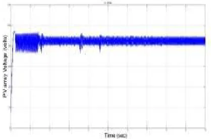
Fig. 6.Output current Vs time curve of the PV panel
Fig. 7.Output voltage Vs time curve of the PV panel
VI. CONCEPTS USED
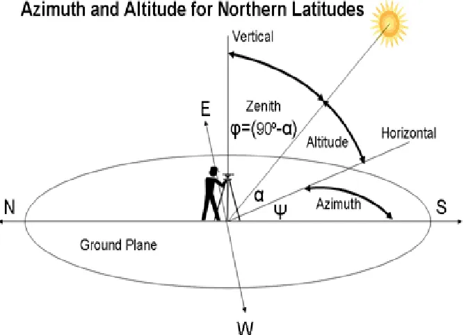
a. Azimuth angle:
Theazimuthis the angle between the north vector and the perpendicular projection of the star (the sun) down onto the
horizon.Azimuthis usually measured in degrees (°). The concept is widely used in navigation, astronomy, engineering,
mapping, mining and artillery. In simpler words it is the angle from which the panel receives sunlight.
b. Zenith angle:
The zenith angle is the angle between the sun and the vertical. The zenith angle is similar to the elevation angle but it is measured from the vertical rather than from the horizontal, thus making the zenith angle = 90° - elevation.
Output power of solar panel:
The global formula to estimate the electricity generated in output of a photovoltaic system is
E = Energy (kWh)
A = Total solar panel Area (m²) r = solar panel yield (%)
H = Annual average solar radiation on tilted panels (shadings not included)
PR = Performance ratio, coefficient for losses (range between 0.5 and 0.9, default value is 0.75)
A mixture of 60 percent sodium nitrate and 40 percent potassium nitrate is employed as the salt storage medium. This salt melts at 220ºC and is maintained in a molten state of 290ºC in the ‘cold’ storage tank. It is then traveled through the receiver where it is heated to 565ºC and then on to a ‘hot’ tank for storage. Hot salt is pumped to a steam generating system when power is needed from the plant. These hot salts produce superheated steam for a conventional Rankine-cycle turbine generator system. From the steam generator, the salt is returned to the cold tank where it is stored and eventually reheated in the receiver.All pipes, valves, and vessels for hot salt were constructed from stainless steel because of its corrosion resistance in the molten-salt environment, while the cold-salt system is made from mild carbon steel. Like all solar technologies, solar power towers are fueled by sunshine and do not release greenhouse gases. Solar power towers are unique among solar electric technologies in their ability to efficiently store solar energy and dispatch electricity to the grid when needed, even at night or during cloudy weather. Schematic representation of azimuth and zenith angles is given in figure 8.
Fig. 8.Schematic representation of Azimuth and Zenith angles
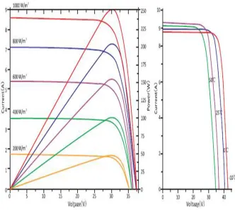
c. Effect of solar radiation variation:
power tower is hybridized with a conventional fossil plant, emissions will be released from the non-solar portion of the plant. In addition, molten salt is used in the chemical and metals industries as a heat-transport fluid, so experience with molten-salt systems exists for non-solar applications. PV Cell power and current Vs voltage curves for different solar irradiations shown in figure 9.
Fig. 9.PV Cell power and current Vs voltage curves for different solar irradiations
VII. CONCLUSION
The objective of this paper is to enhance the efficiency of Photovoltaic panel. Thus, it can be concluded that though the initial investment required for the project is high, it is maintenance free and can surely produce electrical energy free of cost later on. Future scope of this project is that the nearly fail proof tracking system can be implemented to direct the panels precisely towards the sun and hence improve their output voltage.
REFERENCES
[1] “360° sun tracking with automated cleaning system for solar pv modules” Ravi Tejwani, Chetan S Solanki Department of Energy Science and Engineering Indian Institute of Technology Bombay Powai, Mumbai-400076, India Published in: Photovoltaic Specialists Conference (PVSC), 2010 IEEE Date of Conference: 20-25 June 2010 Page(s): 002895 – 002898 ISSN : 0160-8371.
[3]“PLC Based Solar Tracking Panel Assembly” Sushma.V.R , Sneha.V.M , Department of Electrical and Electronics,Manipal Institute of Technology Manipal, Karnataka, India. International Journal of Engineering Trends and Technology (IJETT) – Volume 18 Number 5 – Dec 2014. ISSN: 2231-5381