Abstract— The need for a cleaner environment and the continuous increase in power demands makes renewable energy production like solar and wind increasingly interesting. Energy production using solar energy could be a solution for the ever increasing power demands. This demand overloads the distribution grids as well as the power stations having a negative impact on power quality and availability. One solution to this problem is grid-connected photovoltaic (PV) systems. In this paper we are modeling a three phase photo-voltaic cell based inverter system using MATLAB software. which consists of PV Array, grid system and solar inverter. The system works on Solar power. The goal of this project is to Simulate, design, develops and analyzes the performance of PV based inverter system. The inverter is IGBT bridge based controlled system. The system is tested on resistive and inductive load. Voltage/current waveform analysis, power quality and system analysis is carried out by using power quality analyzer as well as load sharing between photovoltaic array is done. In this model the harmonic compensation of waveform is also introduced. At last, the control circuit, is discussed and designed in MATLAB/Simulink interactive software which results sinusoidal output from the inverter.
Index Terms— 3-Phase, PV Array, Inverter, Grid connected inverter, IGBT, MATLAB/Simulink.
I. INTRODUCTION
The continuously increasing energy consumption overloads the distribution grids as well as the power stations, therefore having a negative impact on power availability, security and quality. One of the solutions for overcoming this is the Distributed Generation (DG) systems. DG systems using renewable energy sources like solar or wind have the advantage that the power is produced in close proximity to where it is consumed minimizing the loss due to transmission lines. In the last decade solar energy technologies have become less expensive and more efficient, which have made it an attractive solution being cleaner and more environmentally friendly energy resource than traditional ones. Nevertheless a PV system is still much more expensive than other methods of energy generation given the high manufacturing costs of PV panels. One of the major advantages of PV technology is that it has no moving parts therefore the hardware is very robust; it has a long lifetime and low maintenance requirements and
most importantly it is one solution that offers environmentally friendly power generation. Nowadays PV panels are present in everyday life: powering wrist watches,
small calculators, supplying loads in remote sites and, and most importantly, they are connected to the public grid, generating the green power of the future. The block diagram is given below.
Fig : Block diagram of PV system II. SYSTEM STRUCTURE AND OPERATION
[1] PHOTOVOLTAIC CELLS THEORY
The ability to generate electrical power by means of converting solar irradiation is called Photo voltaic. It first was characterized in 1839 by Becquerel when he observed two dissimilar materials would develop an electric potential when their junctions where illuminated with photons. Modern Photovoltaic (PV) cells use a semiconductor p-n junction
that after absorbing light energy, results in an increased population of charge carriers with a potential related to the band gap and also into cell heating which degrades the performance. A typical solar cell consists of a 0.2mm thick monocrystalline or polycrystalline silicon wafer having two layers that present different electrical properties enhanced by doping with impurities creating an electric field at the junction area. When sunlight impacts the solar cell the energy from the photons creates free charges that are separated by the electrical field, creating a potential so when a load is placed between the terminals a photo current (I pv) is created. The most common material used in photocells today is silicon (Si) divided in
monocrystalline, polycrystalline, and amorphous. The amount of energy they can deliver changes depending on the material of the cell and the incidence of sunlight. A simple PV cell from a modeling perspective is an ideal current source in parallel with an ideal diode as seen in Figure 2.1. The two parameters used to model and characterize a PV cell are: the open circuit voltage (Voc ) and the short circuit
Simulation and Performance Analysis of Three
Phase PV Array Based Inverter
current (Isc ). The Voc is the maximum voltage which a solar cell can provide at zero current. The Isc is the maximum current which a solar cell can provide at zero voltage. The output current from the PV cell can be found using the equation
I = Isc – Id (i) where Isc is the short circuit current that is equal to the photon generated current and Id is the current shunted thought the
intrinsic diode.
Figure 2.1. Ideal PV cell.
The diode current is given by Shockley’s diode equation:
I
d= I
0* ( e^qVd/kT - 1) (ii)
1. Io is the reverse saturation current of the diode 2. q is the electro charge valued at 1.602x10⁻²³ C 3. Vd is the diode’s voltage
4. k is Boltzmann’s constant valued at 1.381x10⁻²³ J/K 5. T is the junction temperature in Kelvin combining Equation (i) and Equation (ii) we then obtain:
I = I
sc– I
0* ( e^qV/kT - 1) (iii)
In this case V is the voltage that exists across the PV cell and I is the output current of the ideal circuit model.
A single solar cell typically produces only about 0.5V so they need to be connected in series forming what is known as the PV Module. A PV panel is a collection of PV modules physically and electrically grouped together and finally a PV Array is a collection of PV panels. All three configurations follow the same basic modeling equations. The simple PV cell model neglects to take into consideration a series of parameters [3] that create a more accurate model represented in Figure 2.2:
1. The series resistance (Rs): that accounts for any resistance in the current paths through the semiconductor material, the metal grid, contacts and currents controlling the system. This value also accounts for the loss associated with connecting a number of cells in series.
2. The parallel (shunt Rp) resistance: is a loss associated with a slight leakage current through a parallel resistive path to the device. In most models it is neglected because its effect isn’t as noticeable unless a large amount of cells are connected in parallel.
3. A recombination factor related directly to the depletion region of PV cells and to the amount of cells connected in series. Usually it’s represented by a second diode in the equivalent circuit, or characterized by a factor in the
Equation (2.3).
Figure 2.2. More accurate PV model.
Taking into account all the additional elements mentioned the Equation (iii) changes to:
(iv)
where n also is sometimes described as a, being the ideality factor and its value is between 1 and 2 [4]. For the purposes of this research we have adopted the value proposed in [5] of 1.3.
The equivalent final circuit of the PV module is in Figure (iii)
Figure 2.3. Equivalent circuit of PV cell.
The short circuit can be calculated at any given temperature using:
I
sc@T= I
sc@Tref* [1+ K
i– (T – T
ref)] (v)
Isc at the reference temperature is found on the datasheet, and a refers to the temperature coefficient of Isc in percent change per degree. Both measurements are done under the standard irradiance of 1000W/m2. Normally the reference temperature is 25 C. The photon generated current also varies based on the irradiance (G) according to the following equation:
I
sc@G= I
sc@Gref* [G/G
ref] (iv)
Combining both equations and simplifying we then obtain a generic expression for the short circuit current. The assumption that Isc ≈ Ipv is generally used since the series resistance is low and the parallel resistance is high, leading then to:
I
pv= (I
sc+ K
iΔT )G/G
n(iiv)
The last term of Equation (iv) is Io that is dependent on temperature described by equation:
[2] Three Phase Inverter
Power Inverter is a device that converts a DC source into an AC source. Power inverters produce one of three different types of wave output:
1. Square Wave
2. Modified Square Wave or Modified Sine wave 3. Pure Sine Wave or True Sine Wave
The three different wave signals represent three different qualities of power output.
A three phase inverter’s topology was presented in Figure c.
.
Figure c. Simulink three phase inverter.
Similar to the single phase inverter the three phase inverter can be connected or not to the grid to function properly and it is used to synchronize before switching to current control.
III. SIMULATION AND RESULT
In the given paper simulation of solar cell and total inverter system is carried out in MATLAB software.
PV array simulation
Usually the solar cells are modeled using a specific type of equivalent circuit a photovoltaic model is based on diode behavior, which gives to photovoltaic cell its exponential characteristic. In Simulink the solar cell can be modeled with three modeling systems .The solar cell from MATLAB is a solar current source, which includes solar induced current and temperature dependence. This block allows choosing one of two models: a model with 8 parameters in which describes the output current, and a model with 5 parameters if for this equation is applied the following simplifying assumptions: the impedance of the parallel resistor is infinite and the saturation current of the second diode is zero. The model with 5 parameters allows optimization of this block according to the equivalent circuit model parameters or by short circuit current and open circuit voltage. The model shown in Figure d represents a PV cell array connected to a variable resistor. This resistor has an input ramp which just
varies resistance linearly in closed circuit until it reaches the 25steps.
Fig. d: Simulink model of PV array.
The advantage of using of this high level of implementation is to create a simple equivalent circuit, which have much more complex parameters, including the effect of temperature in the device which is very important for behaviour of this type of system. The photovoltaic panel model is validated by simulating at a value of irradiance of 1000 W /m2 and a temperature of 25°C.
Parameter
Value
Short Circuit Current [A]
Isc=3.12
Open Circuit Voltage [V] VOC=1.2 Quality Factor N=1.5 Series Resistance [Ω] RS=0
First Order Temp-Coefficient for Iph
TIPH1=0 Temperature exponent for Rs TRSI=0 Parameter Extraction
Temperature
25°C
Fixed Circuit Temperature TFIXED= 25°C I-Parameters of Solar cell in MATLAB Simulink The V-I and V-P characteristics of the photovoltaic array is given in Figure e and Figure f. The V-I curve represent the standard behavior of the photovoltaic cell and photovoltaic array respectively.
Fig. e: V-I characteristics of photovoltaic array
Fig. f: V-P characteristics of the photovoltaic array
Simulation of total solar inverter system
The simulation of total solar inverter system is shown in Fig g. The solar cell array is connected with IGBT based inverter which further connected to the LC filter. The output voltage is 430 V.
Fig. g: Simulation of Solar inverter system Simulation is carried out in MATLAB software.
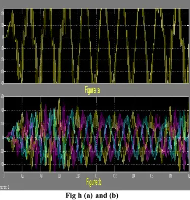
Fig h (a) and (b)
Fig h (a) and (b) shows the results for output voltages. The magnitude is 448 and angle between them is -11.21 respectively.
This output is taken from LC filter. The waveforms are some more variation.
But after the AC Break and timer system the variation between waveforms become less as shown in fig.i (a) & (b).
Fig i (a) and (b)
IV.CONCLUSION
This paper presented a three phase IGBT based Inverter, which uses single DC source and PV system as DC source and connected to three phase grid system is used as load to observe the performance characteristics of the inverter. Use
of IGBT inverter reduces the cost of multiphase solar inverter considerably. By this topology, get the better output waveform from the system. The advantage of this topology is help to decrease the cost. MATLAB/SIMULINK software allows us to model the grid connected photovoltaic (PV) system which is useful to understand and master the performance of PV systems by optimizing the design and lowering the costs by shortening the development cycles as well as to improve the systems reliability and efficiency.
REFERENCES
[1] Vikas Kulkarni, Rajesh Nehete, “Simulation and Analysis of Photo-Voltaic (PV) based Solar Inverter System” (IJSCE) ISSN: 2231-2307, Volume-3, Issue-6, January 2014.
[2] R. A. Messenger and J. Ventre, Photovoltaic System Engineering,CRC, 2nd ed., 2003.
[3] J. Hu, J. Zhang, and H. Wu, “A novel mppt control algorithm based on numerical calculation for pvgeneration systems,”
[4] F. Luo, P. Xu, Y. Kang, and S. Duan, “A variable step maximum power point tracking method usingdifferential equation solution,” 2007 Second IEEE Conference on Industrial Electronics and Applications,pp. 2259–2263, 2007.
[5] W. Swiegers and J. H. Enslin, “An integrated maximum power point tracker for photovoltaic panels,”Industrial Electronics, 1998. Proceedings. ISIE ’98. IEEE International Symposium on, pp. 40–44, July1998.
[6] S.B. Kjær, J.K. Pedersen, F. Blaabjerg, Power inverter topologies for photovoltaic modules – a review,IEEE proc. of the 37th annual industry application conference (IAS’02), vol. 2, pp. 782-788, 2002.
[7] P929 Recommended Practice for Utility Interface of Photovoltaic (PV) Systems’,IEEE, Sep 1998.
[8] Osorio, C., Recorded Webinar-Model-Based Design for Solar Power Systems.
[9] Vandana Khanna’s “MATLAB/SIMELECTRONICS Models Based Study of Solar Cells”, InternationalJournal Of Renewable Energy Research Vol.3, No.1, 2013.
[10] Marcel ISTRATE “Modeling And Simulation Of Photovoltaic Arrays”.
BIOGRAPHY
Mohammad Omair Belong to UP Received his
Bachelor of Technology degree from Uttar Pradesh Technical University, Allahabad in 2010. He is pursuing his M.Tech in Electrical Engg. (Power Electronics) from SHIATS, Allahabad, UP-India.
Pratibha Tiwari presently working as Assistant Professor in Electrical & Electronics Engineering at Sam Higginbottom Institute of Agriculture Technology & Sciences, Allahabad, (U.P) India. The degree of B.Tech secured in Electrical & Electronics Eng. from UCER, Allahabad in 2002 and M.Tech. in Control and Instrumentation from MNNIT, Allahabad in 2006. Research interest includes Control & Instr. and Power Electronics.