414 ISSN: 2278 – 7798 All Rights Reserved © 2016 IJSETR
IMPLEMENTATION
OF
DUAL-DIRECTION
SUNTRACKING
SOLAR
SYSTEM
USING
AT89C52
MICROCONTROLLER
Pavani Kollamudi
Assistant Professor in Department of Electronics and Instrumentation Engineering
LAKIREDDY BALI REDDY COLLEGE OF ENGINEERING (Autonomous) Mylavaram, A.P., INDIA
ABSTRACT
The recent decades have seen the increase in demand for reliable and clean form of electricity derived from renewable energy sources. One such example is solar power. Vast amount of energy is available within the core of sun[1]. The energy that is received from sun in an hour is more than that is consumed by us in a year [7]. If human race is able to capture even 1% of the total energy which sun delivers then we can cater the need of our race for decades. Efforts are continuously being made to capture as much energy as we can in order to store most of the energy which se are getting. In this paper a device called solar tracker has been discussed. Solar panels give maximum output when the plane of the solar collector is normal to incident radiations [8].
The challenge remains to maximize the capture of the rays from the sun for conversion into electricity. This paper presents fabrication and installation of a solar panel mount with a dual-direction solar tracking controller. This is done so that rays from the sun fall perpendicularly unto the solar panels to maximize the capture of the rays by pointing the solar panels towards the sun and following its path across the sky. Thus electricity and efficiency increased.
KEYWORDS: Solar Tracker, DC (Analog to Digital Convertor), Microcontroller, LCD and LDR
1. INTRODUCTION
The Main objective of the paper is to control the solar panel movement according to the movement of sun. It is useful to produce the maximum energy from the solar panel according to the tangential light rays focused on the solar cell. For the purpose of practical demonstration we have constructed solar panel by using LDR’s sun is nothing but the laser light. The paper is designed with Micro Controller 8051, motor driven circuits, LDR’s and voltage comparators. The solar panel attached to the linear motor rotating towards the forward directions and reverse directions. There are two limit switches attached to the motor to restrict the rotation for 270.
Initially the program written in micro controller scans for the maximum light intensity focused on the solar panel then stop’s rotation. When the light intensity is decreased again it looks for maximum light intensity and moving in incrementing direction. Again it stops rotation at maximum value. The rotating direction may be clockwise or anticlockwise. All LDR’s, limit switches are connected to the input port, motor is connected to
output port of Micro Controller. It is a useful paper for the general public to rotate the solar panel in the direction of sun.
Figure 1. Block Diagram of DUAL-DIRECTION
SUNTRACKINGSOLARSYSTEM
Solar cells or photovoltaic cells are semiconductor diodes that convert available sunlight (at least a portion) into electrical power[3]. They are basically P-N junction photodiodes with very large light-sensitive area [5]. Each photodiode is a solar cell. All these cells are connected inside a module to form a solar panel. These solar panels are cascaded together to form arrays to generate high power electricity[6].
A photovoltaic panel is a device used to capture the sun’s radiation. These panels consist of an array of solar cells. The solar cells are made up of silicon (sand). They are then connected to complete a photovoltaic (solar) panel. When the sun rays are incident on the solar cell, due to the photovoltaic effect, light energy from the sun is used to convert it to electrical energy. The solar panels can be mounted as a fixed type or used as a tracker type. In the fixed type, the solar panel is mounted on the surface of the roof or ground irrespective of sun’s
415 ISSN: 2278 – 7798 All Rights Reserved © 2016 IJSETR
direction at a particular angle [2].
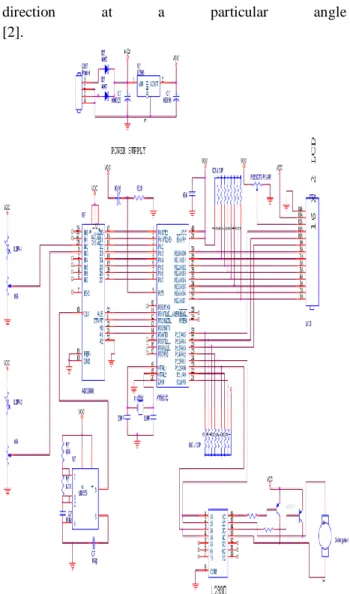
Figure 2. Schematic diagram
A Single axis tracking system is a method where the solar panel tracks the sun from east to west using a single pivot point to rotate. Under this system there are three types: Horizontal single axis tracking system, Vertical single axis tracking system and Tilted single axis tracking system. In the Horizontal system the axis of rotation is horizontal with respect to the ground, and the face of the module is oriented parallel to the axis of rotation. In the Vertical system the axis of rotation is vertical with respect to the ground and the face of the module is oriented at an angle with respect to the axis of rotation. In the Tilted tracking system the axes of rotation is between horizontal and vertical axes and this also has the face of the module oriented parallel to the axis of rotation, similar to the Horizontal tracking system. The single axis tracking system consist of two LDR’s placed on either side of the panel. Depending on the intensity of the sun rays one of the two LDR’s will be shadowed and the other will be illuminated [2].The LDR with the maximum intensity of the sun’s radiation sends stronger signal to the controller which inturn sends
signal to the motor to rotate the panel in the direction in which the sun’s intensity is maximum[3].
Commercial made solar trackers are a nice addition to any solar panel array. They help increase the time that panels directly face the sun and allow them to produce their maximum power. Unfortunately they can be expensive to buy. To reduce its cost solar tracking can be done using time instead of using a device that would sense where the sun is and move the panels toward it[4].
2. MICROCONTROLLER AT89C52
Microprocessors and microcontrollers stem from the basic idea. The contrast between a microcontroller and a microprocessor is best exemplified by the fact that most microprocessors have many operational codes (opcodes) for moving data from external memory to the CPU; microcontrollers have one or two. Microprocessors have one or two types of bit handling instructions; microcontrollers will have many. The microprocessor is concerned with rapid movement of code and data from external addresses to the chip; the microcontroller is concerned with rapid movement of bits within the chip. The microcontroller can function as a computer with the addition of no external digital parts; the microprocessor must have additional parts to be operational.
The AT89C52 is a low power, high performance CMOS 8-bit microcontroller with 8K bytes of in-system programmable Flash memory. The device is manufactured using Atmel’s high-density nonvolatile memory technology and is compatible with the industry standard 80C51 instruction set and pin out. The on-chip Flash allows the program memory to be reprogrammed in-system or by a conventional nonvolatile memory programmer.
3. ADC0808/ADC0809
Bit MP Compatible A/D Converters with 8-Channel Multiplexer. The ADC0808, ADC0809 data acquisition component is a monolithic CMOS device with an 8-bit analog-to-digital converter, 8-channel multiplexer and microprocessor compatible control logic. The 8-bit A/D converter uses successive approximation as the conversion technique. The converter features a high impedance chopper comparator, a 256R voltage divider with analog switch tree and a successive approximation register.
The 8-channel multiplexer can directly access any of 8-single-ended analog signals. The device eliminates the need for external zero and full-scale adjustments. Easy interfacing to microprocessors is provided by the latched and decoded multiplexer address inputs and latched TTL TRI-STATE® outputs. The design of the ADC0808, ADC0809 has been optimized by incorporating the most desirable aspects of several A/D conversion techniques. The ADC0808, ADC0809 offers high speed, high accuracy, minimal temperature
416 ISSN: 2278 – 7798 All Rights Reserved © 2016 IJSETR
dependence, excellent long-term accuracy and repeatability, and consumes minimal power. These features make this device ideally suited to applications from process and machine control to consumer and automotive applications.
4. LIQUID CRYSTAL DISPLAY
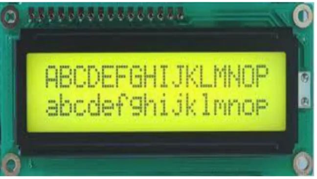
Liquid crystal display is a type of display used in digital watches and many portable computer.
Figure 3. Liquid Crystal Display
LCD displays utilize two sheets of polarizing material with a liquid crystal solution between them. An electric current passed through the liquid causes the crystals to align so that light cannot pass through them. Each crystal, therefore, is like a shutter, either allowing light to pass through or blocking the light. The liquid crystals can be manipulated through an applied electric voltage so that light is allowed to pass or is blocked. By carefully controlling where and what wavelength (color) of light is allowed to pass, the LCD monitor is able to display images. A back light provides LCD monitor’s brightness.
Other advances have allowed LCD’s to greatly reduce liquid crystal cell response times. Response time is basically the amount of time it takes for a pixel to “change colors”. In reality response time is the amount of time it takes a liquid crystal cell to go from being active to inactive.
Here the LCD is used at both the Transmitter as well as the receiver side. The input, which we give to the microcontroller, is displayed on the LCD of the transmitter side and the message sent is received at the receiver side, which displays at the receiver end of the LCD and the corresponding operation is performed.
5. LIGHT DEPENDENT RESISTOR
A photo resistor or light dependent resistor or cadmium sulfide (CdS) cell is a resistor whose resistance decreases with increasing incident light intensity. It can also be referenced as a photoconductor. A photoresistor is made of a high resistance semiconductor. If light falling on the device is of high enough frequency, photons absorbed by the
semiconductor give bound electrons enough energy to jump into the conduction band. The resulting free electron (and its hole partner) conduct electricity, thereby lowering resistance.A photoelectric device can be either intrinsic or extrinsic. An intrinsic semiconductor has its own charge carriers and is not an efficient semiconductor, e.g. silicon. In intrinsic devices the only available electrons are in the valence band, and hence the photon must have enough energy to excite the electron across the entire bandgap. Extrinsic devices have impurities, also called dopants, added whose ground state energy is closer to the conduction band; since the electrons do not have as far to jump, lower energy photons (i.e., longer wavelengths and lower frequencies) are sufficient to trigger the device. If a sample of silicon has some of its atoms replaced by phosphorus atoms (impurities), there will be extra electrons available for conduction. This is an example of an extrinsic semiconductor.
6. PROGRAM SOURCE CODE WRITTEN FOR SOLAR PANEL CONTROL ADC
;P2.0 = MOTOR ;P2.1 = MOTOR ;P1 = ADC DATA ;P3.5=B ;P3.4=A ;P3.3=START ;P3.2=ALE ;P0 = DISP DATA ;P2.7 = RS ;P2.6 = R/W ;P2.5 = EN ;ADC CH0 LDR1 ;ADC CH1 LDR2
; 50H = DISP LOCATION ADD ; 51H = DISP VALUE ; 70H = LDR1 DATA ; 71H = LDR2 DATA ORG 0 LJMP START ORG 0050H START: CLR P2.0 CLR P2.1 LCALL LCDINI LCALL DEL MOV DPTR,#0900H LCALL TLINE MOV DPTR,#0910H LCALL BLINE LCALL SSEC MOV DPTR,#0920H LCALL TLINE MOV DPTR, #0930H LCALL BLINE
;********* READ VAL DISP *********** XX1:CLR P3.5
417 ISSN: 2278 – 7798 All Rights Reserved © 2016 IJSETR
CLR P3.4 LCALL VSEN MOV 50H,#8CH MOV A,51H MOV 70H,A LCALL VFDIS ;--- SETB P3.5 CLR P3.4 LCALL VSEN MOV A,51H MOV 71H,A MOV 50H,#CCH MOV A,51H LCALL VFDIS ;--- CLR A MOV A,70H ADD A ,0AH
MOV 72H,A ;UPPER LIMIT CLR A
MOV A,70H SUB A,0AH
MOV 73H,A ;LOWER LIMIT MOV 75H,#00H LCALL VCOMP1 LCALL VCOMP2 ;****************************** CLR A MOV A,75H CJNE A,#01H,XX2 CLR P2.0 SETB P2.1 LCALL DEL10 CLR P2.0 CLR P2.1 LCALL DEL10 LJMP XX1 XX2: CJNE A,#02H,XX3 SETB P2.0 CLR P2.1 LCALL DEL10 CLR P2.0 CLR P2.1 LJMP XX1 XX3: LJMP XX1 ;********** LCD INI ************ LCDINI:CLR P0.0 CLR P0.1 CLR P0.2 CLR P2.5 CLR p2.7 CLR p2.6 MOV P0,#30H LCALL WRI CLR p2.7 CLR p2.6 RET ;--- TLINE: CLR p2.7 CLR p2.6 MOV P0,#80H LCALL WRI MOV R7,#00H TKL: CLR A MOVC A,@A+DPTR MOV P0,A LCALL WRD INC DPTR INC R7 CJNE R7,#10H,TKL RET BLINE: CLR p2.7 CLR p2.6 MOV P0,#C0H LCALL WRI MOV R7,#00H BKL: CLR A MOVC A,@A+DPTR MOV P0,A LCALL WRD INC DPTR INC R7 CJNE R7,#10H,BKL RET
;***** INSTRUCTION /DATA WRITE** WRI: SETB P2.5 MOV R0,#FFH DJNZ R0,$ CLR P2.5 MOV R0,#FFH DJNZ R0,$ RET WRD: SETB p2.7 ; REGISTER CLR p2.6 ;READ WRITE SETB P2.5 ;ENABLE MOV R0,#FFH DJNZ R0,$ CLR P2.5 CLR p2.6 CLR p2.7 RET ;****************************** DEL: MOV R7,#FFH DJNZ R7,$RET DEL1: MOV R7,#FFH DJNZ R7,$ RET SEC: MOV R5,#03H M1: MOV R6,#FFH M2: MOV R7,#FFH M3: DJNZ R7,M3 DJNZ R6,M2 DJNZ R5,M1 RET SSEC: MOV R5,#1FH
418 ISSN: 2278 – 7798 All Rights Reserved © 2016 IJSETR
SM1: MOV R6,#FFH SM2: MOV R7,#FFH SM3: DJNZ R7,SM3 DJNZ R6,SM2 DJNZ R5,SM1 RET ;***************************************** XDEL:mov r4,#0FH djnz r4,$ RET XDEL1: mov r4,#0FH djnz r4,$ RET
DEL10: MOV R5,#AFH GB: MOV R4,#FFH DJNZ R4,$ DJNZ R5,GB RET ;*********** DISPLAY ************* VFDIS: MOV PSW,#18H MOV R3,51H CLR A MOV A,50H MOV P0,A LCALL WRI
MOV DPTR,#0400H ;DATA BASE CJNE R3,#00H,GHH LJMP DTX GHH: MOV R2,#03H GHG: INC DPTR DJNZ R2,GHG DJNZ R3,GHH DTX:CLR A MOVC A,@A+DPTR MOV P0,A LCALL WRD INC DPTR CLR A MOVC A,@A+DPTR MOV P0,A LCALL WRD INC DPTR CLR A MOVC A,@A+DPTR MOV P0,A LCALL WRD INC DPTR MOV PSW,#00H RET ;********* VOLTAGE SENSE ************ VSEN: mov p1,#FFH ;mov p3,#FFH SETB P3.2 SETB P3.3 ;SETB P3.4 ;SETB P3.5 SETB P3.6 SETB P3.7 CLR P3.2 CLR P3.3 LCALL DEL LCALL DEL SETB P3.2 LCALL DEL SETB P3.3 LCALL DEL CLR P3.2 LCALL DEL CLR P3.3 LCALL SEC MOV R6,P1 MOV 51H,R6 LCALL XDEL RET
7. RESULTS & CONCLUSION
The Main objective of this paper is to control the solar panel movement according to the movement of sun. It is useful to produce the maximum energy from the solar panel according to the tangential light rays focused on the solar cell. For the purpose of practical demonstration we have constructed solar panel by using LDR’s sun is nothing but the laser light. It is designed with Micro Controller 8052 and motor, motor driven circuits, LDR’s and voltage comparators.
Figure 4. Real time DUAL-DIRECTION
SUNTRACKINGSOLARSYSTEM
The solar panel attached to the linear motor rotating towards the forward directions and reverse directions. There are two limit switches attached to the motor to restrict the rotation for 270.
419 ISSN: 2278 – 7798 All Rights Reserved © 2016 IJSETR
Initially the program written in micro controller scans for the maximum light intensity focused on the solar panel then stop’s rotation. When the light intensity is decreased again it looks for maximum light intensity and moving in incrementing direction. Again it stops rotation at maximum value. The rotating direction may be clockwise or anticlockwise. All LDR’s, limit switches are connected to the input port, motor is connected to output port of Micro Controller.
It is a useful paper for the general public to rotate the solar panel in the direction of sun. For future work, we plan to improve our paper. Based up on this technique we can construct electric power generation station. We can replace the present ways of electricity generation by solar energy.
8. BIBLIOGRAPHY
[1] Bhavesh Pandey1, Anita Agrawal2: Automatic Sun Tracking System Using PSoC International Journal of Innovative Research in Science, Engineering and Technology Vol. 1, Issue 1, November 2012 pp. 66-70. [2] Deepthi.S, Ponni.A, Ranjitha.R, R Dhanabal.: Comparison of Efficiencies of Single-Axis Tracking System and Dual-Axis Tracking System with Fixed Mount International Journal of Engineering Science and Innovative Technology (IJESIT) Volume 2, Issue 2, March 2013.
[3] Dhanabal.R1, Bharathi.V2, Ranjitha.R3 , Ponni.A4,
Deepthi.S5 ,Mageshkannan.P6
Comparison of Efficiencies of Solar Tracker systems with static panel Single-Axis Tracking System and Dual-AxisTracking System with Fixed Mount International Journal of Engineering and Technology (IJET) Vol 5 No 2 Apr-May 2013.
[4] Shrishti Rana A STUDY ON AUTOMATIC DUAL AXIS SOLAR
TRACKER SYSTEM USING 555 TIMER published in International Journal of Technical Research and Applications e-ISSN: 2320-8163,Volume 1, Issue 4 PP. 77-85. [5] SolarPower http://www.solar-power-answers.co.uk/basics.php [6]SolarGreenhttp://www.solargreen.net.au/solarcell.php [7] NANOCO group PLC, http://www.nanocotechnologies.com/content/Commercia lApplications/Solar.aspx
[8] J. Rizk, and Y. Chaiko, “Solar Tracking System: More Efficient Use of Solar Panels”, World Academy of Science
BIOGRAPHY
PAVANI KOLLAMUDI is currently working as an Assistant professor in the Dept. of Electronics and
Instrumentation Engineering of LAKIREDDY BALI REDDY COLLEGE OF ENGINEERING (Autonomous) Mylavaram, A.P., INDIA which is affiliated to JNTU Kakinada. Received the M.Tech degree from Nagarjuna University and B.E. degree from Andhra University. Her current research interest includes MEMS, Embedded C, & VLSI System design.